glove box SUZUKI SWIFT 2005 2.G Service Workshop Manual
[x] Cancel search | Manufacturer: SUZUKI, Model Year: 2005, Model line: SWIFT, Model: SUZUKI SWIFT 2005 2.GPages: 1496, PDF Size: 34.44 MB
Page 941 of 1496
Downloaded from www.Manualslib.com manuals search engine Heater and Ventilation: 7A-5
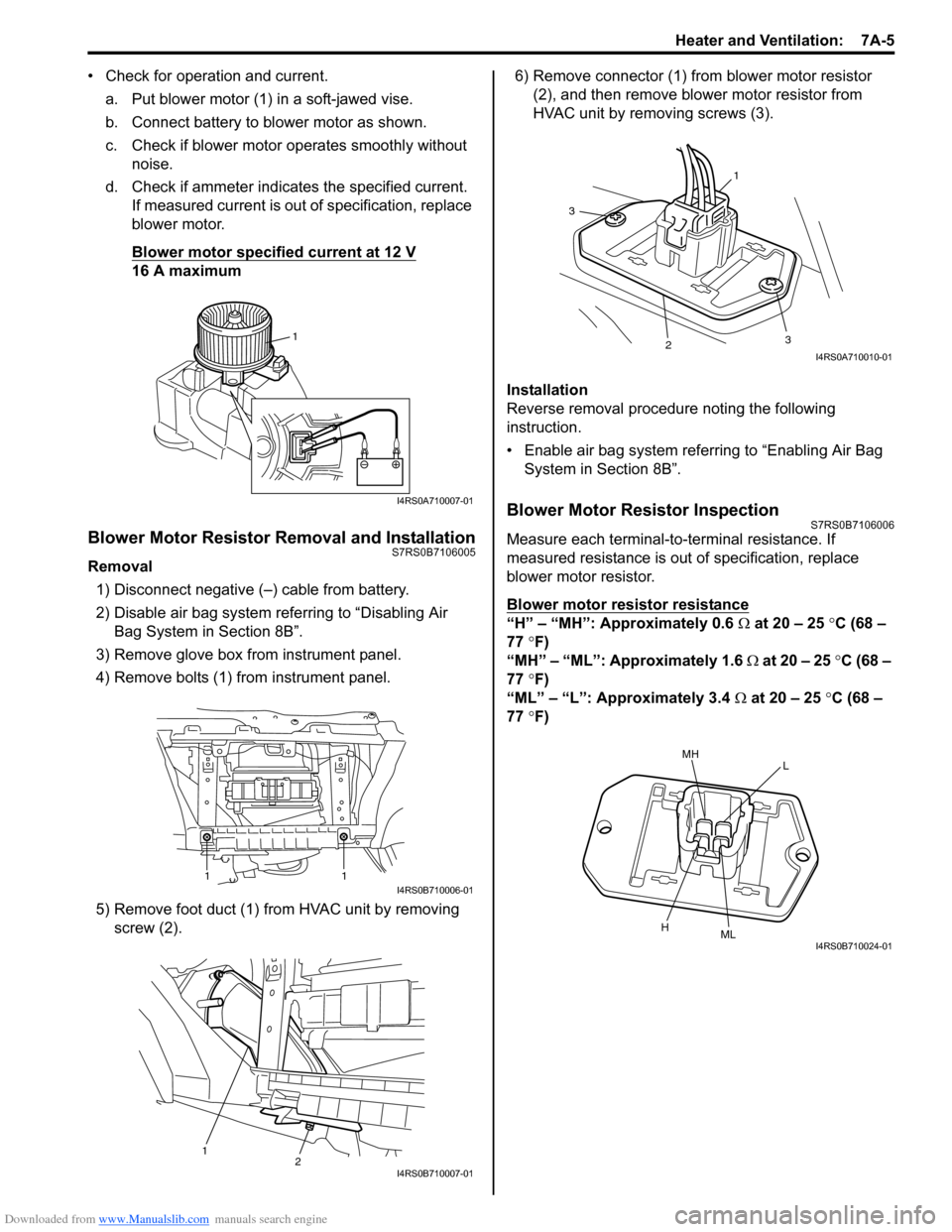
• Check for operation and current.a. Put blower motor (1) in a soft-jawed vise.
b. Connect battery to blower motor as shown.
c. Check if blower motor operates smoothly without noise.
d. Check if ammeter indicates the specified current. If measured current is out of specification, replace
blower motor.
Blower motor specified current at 12 V
16 A maximum
Blower Motor Resistor Removal and InstallationS7RS0B7106005
Removal
1) Disconnect negative (–) cable from battery.
2) Disable air bag system referring to “Disabling Air Bag System in Section 8B”.
3) Remove glove box from instrument panel.
4) Remove bolts (1) from instrument panel.
5) Remove foot duct (1) from HVAC unit by removing screw (2). 6) Remove connector (1) from blower motor resistor
(2), and then remove blower motor resistor from
HVAC unit by removing screws (3).
Installation
Reverse removal procedure noting the following
instruction.
• Enable air bag system referring to “Enabling Air Bag System in Section 8B”.
Blower Motor Resistor InspectionS7RS0B7106006
Measure each terminal-to-terminal resistance. If
measured resistance is out of specification, replace
blower motor resistor.
Blower motor resistor resistance
“H” – “MH”: Approximately 0.6 Ω at 20 – 25 °C (68 –
77 °F)
“MH” – “ML”: Approximately 1.6 Ω at 20 – 25 °C (68 –
77 °F)
“ML” – “L”: Approximately 3.4 Ω at 20 – 25 °C (68 –
77 °F)
1
I4RS0A710007-01
11I4RS0B710006-01
12I4RS0B710007-01
1
3
23
I4RS0A710010-01
MHL
HMLI4RS0B710024-01
Page 947 of 1496
Downloaded from www.Manualslib.com manuals search engine Heater and Ventilation: 7A-11
Side Ventilation Louver Removal and
Installation
S7RS0B7106015
Driver side ventilation louver
Removal1) Disconnect negative (–) cable from battery.
2) Disable air bag system referring to “Disabling Air Bag System in Section 8B”.
3) Remove steering column hol e cover from instrument
panel.
4) Remove combination meter cluster panel from instrument panel, and then disconnect connectors
from front fog lamp switch, illumination cancel switch
and headlight leveling switch (if equipped) of
combination meter cluster panel.
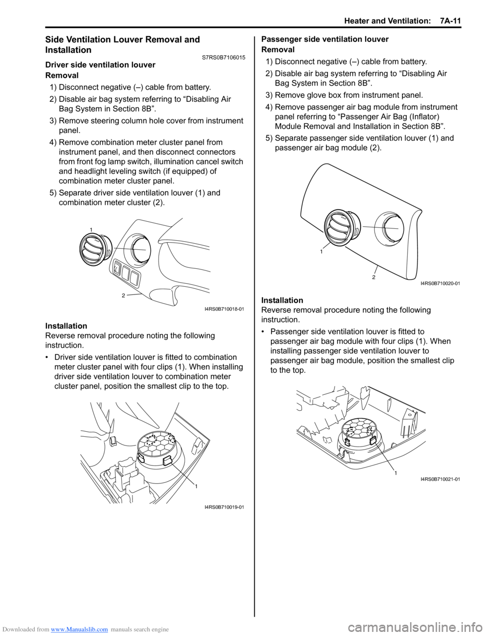
5) Separate driver side ventilation louver (1) and combination meter cluster (2).
Installation
Reverse removal procedure noting the following
instruction.
• Driver side ventilation louver is fitted to combination meter cluster panel with four clips (1). When installing
driver side ventilation louv er to combination meter
cluster panel, position the smallest clip to the top. Passenger side ventilation louver
Removal
1) Disconnect negative (–) cable from battery.
2) Disable air bag system referring to “Disabling Air Bag System in Section 8B”.
3) Remove glove box from instrument panel.
4) Remove passenger air bag module from instrument panel referring to “Passenger Air Bag (Inflator)
Module Removal and Installation in Section 8B”.
5) Separate passenger side ventilation louver (1) and passenger air bag module (2).
Installation
Reverse removal procedure noting the following
instruction.
• Passenger side ventilation louver is fitted to passenger air bag module with four clips (1). When
installing passenger side ventilation louver to
passenger air bag module, position the smallest clip
to the top.
2
1
I4RS0B710018-01
1
I4RS0B710019-01
2
1
I4RS0B710020-01
1I4RS0B710021-01
Page 948 of 1496
Downloaded from www.Manualslib.com manuals search engine 7A-12 Heater and Ventilation:
HVAC Air Filter Removal and Installation (If
Equipped)
S7RS0B7106016
Removal1) Remove glove box from instrument panel.
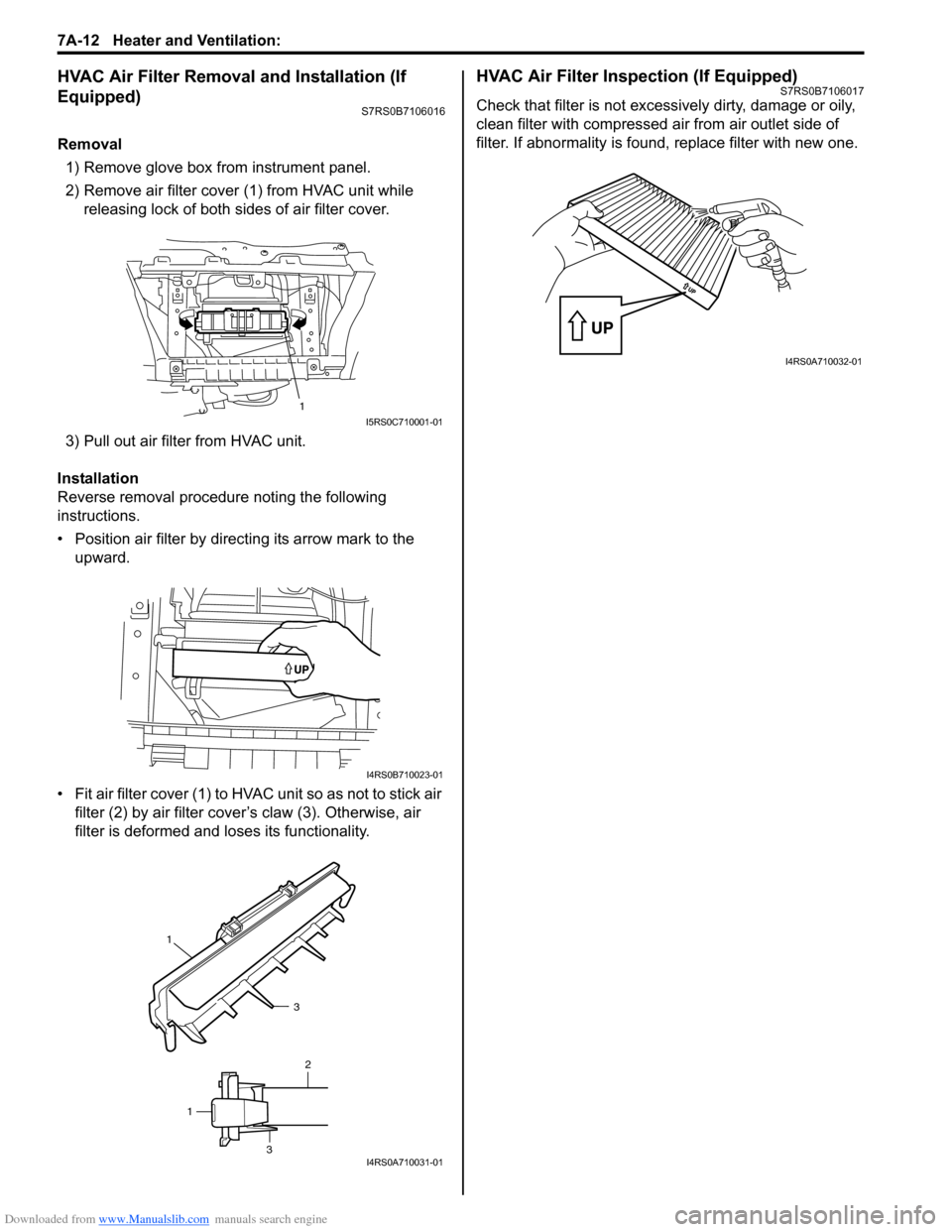
2) Remove air filter cover (1) from HVAC unit while
releasing lock of both sides of air filter cover.
3) Pull out air filter from HVAC unit.
Installation
Reverse removal procedure noting the following
instructions.
• Position air filter by directing its arrow mark to the upward.
• Fit air filter cover (1) to HVAC unit so as not to stick air
filter (2) by air filter cove r’s claw (3). Otherwise, air
filter is deformed and loses its functionality.
HVAC Air Filter Inspection (If Equipped)S7RS0B7106017
Check that filter is not excessively dirty, damage or oily,
clean filter with compressed air from air outlet side of
filter. If abnormality is found, replace filter with new one.
1I5RS0C710001-01
I4RS0B710023-01
1
3
2
1
3I4RS0A710031-01
I4RS0A710032-01
Page 1064 of 1496
Downloaded from www.Manualslib.com manuals search engine 8B-26 Air Bag System:
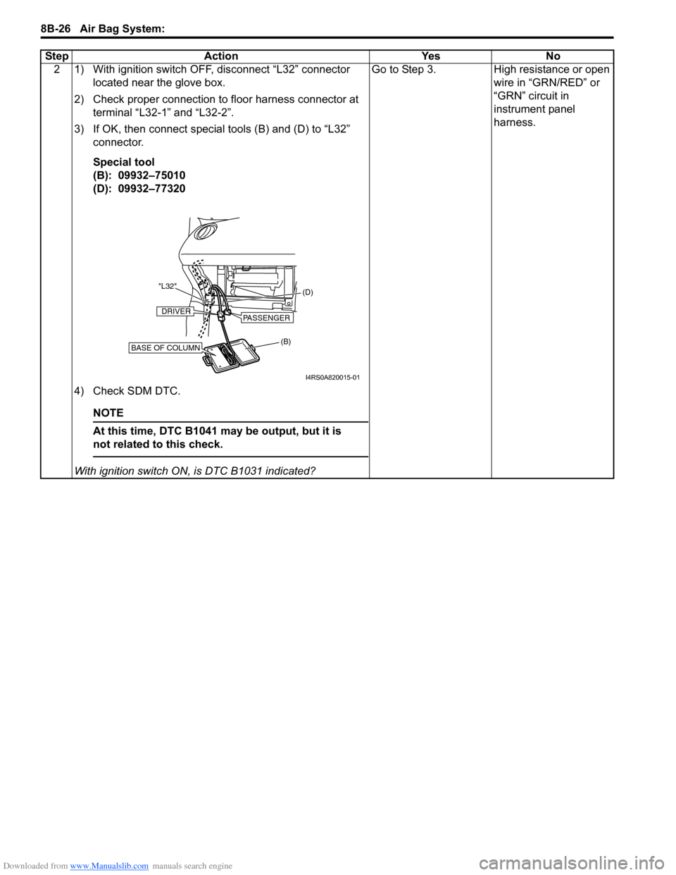
2 1) With ignition switch OFF, disconnect “L32” connector located near the glove box.
2) Check proper connection to floor harness connector at terminal “L32-1” and “L32-2”.
3) If OK, then connect special tools (B) and (D) to “L32” connector.
Special tool
(B): 09932–75010
(D): 09932–77320
4) Check SDM DTC.
NOTE
At this time, DTC B1041 ma y be output, but it is
not related to this check.
With ignition switch ON , is DTC B1031 indicated? Go to Step 3. High resistance or open
wire in “GRN/RED” or
“GRN” circuit in
instrument panel
harness.
Step Action Yes No
(B) (D)
"L32"BASE OF COLUMN
DRIVERPASSENGER
I4RS0A820015-01
Page 1069 of 1496
Downloaded from www.Manualslib.com manuals search engine Air Bag System: 8B-31
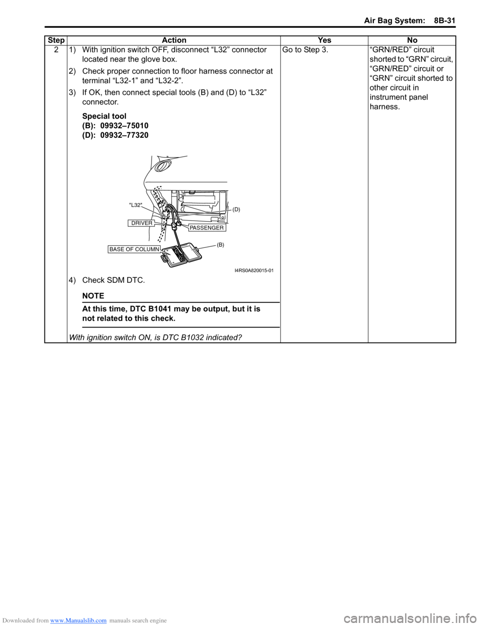
2 1) With ignition switch OFF, disconnect “L32” connector located near the glove box.
2) Check proper connection to floor harness connector at terminal “L32-1” and “L32-2”.
3) If OK, then connect special tools (B) and (D) to “L32” connector.
Special tool
(B): 09932–75010
(D): 09932–77320
4) Check SDM DTC.
NOTE
At this time, DTC B1041 ma y be output, but it is
not related to this check.
With ignition switch ON , is DTC B1032 indicated? Go to Step 3. “GRN/RED” circuit
shorted to “GRN” circuit,
“GRN/RED” circuit or
“GRN” circuit shorted to
other circuit in
instrument panel
harness.
Step Action Yes No
(B)
(D)
"L32"BASE OF COLUMN
DRIVERPASSENGER
I4RS0A820015-01
Page 1074 of 1496
Downloaded from www.Manualslib.com manuals search engine 8B-36 Air Bag System:
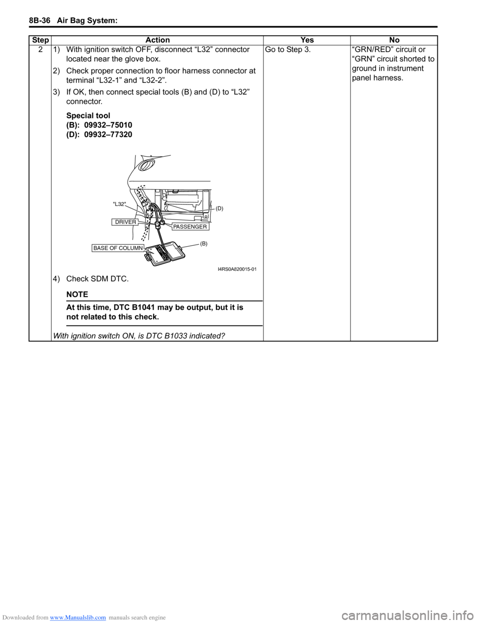
2 1) With ignition switch OFF, disconnect “L32” connector located near the glove box.
2) Check proper connection to floor harness connector at terminal “L32-1” and “L32-2”.
3) If OK, then connect special tools (B) and (D) to “L32” connector.
Special tool
(B): 09932–75010
(D): 09932–77320
4) Check SDM DTC.
NOTE
At this time, DTC B1041 ma y be output, but it is
not related to this check.
With ignition switch ON , is DTC B1033 indicated? Go to Step 3. “GRN/RED” circuit or
“GRN” circuit shorted to
ground in instrument
panel harness.
Step Action Yes No
(B) (D)
"L32"BASE OF COLUMN
DRIVERPASSENGER
I4RS0A820015-01
Page 1079 of 1496
Downloaded from www.Manualslib.com manuals search engine Air Bag System: 8B-41
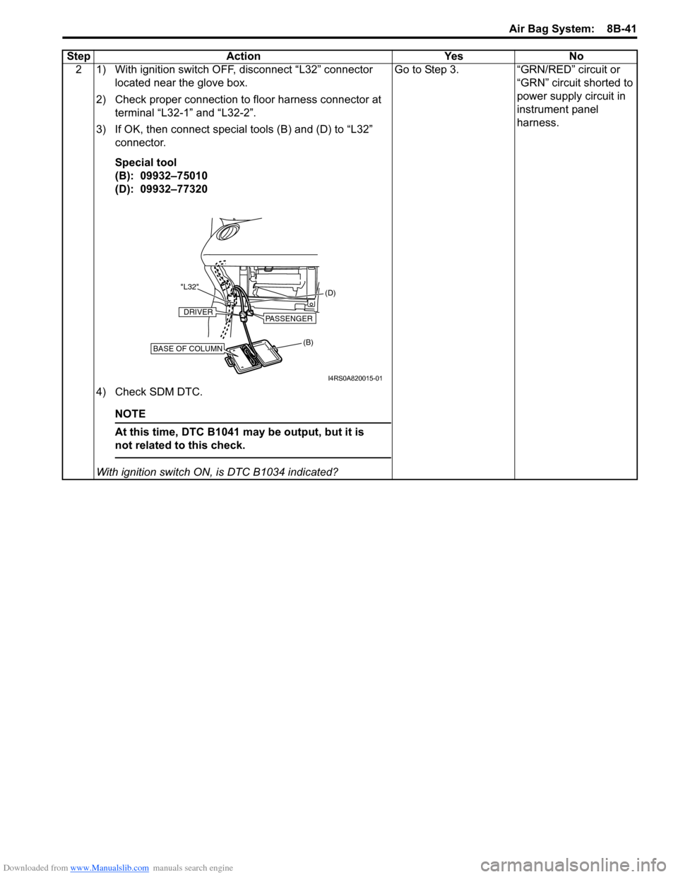
2 1) With ignition switch OFF, disconnect “L32” connector located near the glove box.
2) Check proper connection to floor harness connector at terminal “L32-1” and “L32-2”.
3) If OK, then connect special tools (B) and (D) to “L32” connector.
Special tool
(B): 09932–75010
(D): 09932–77320
4) Check SDM DTC.
NOTE
At this time, DTC B1041 ma y be output, but it is
not related to this check.
With ignition switch ON , is DTC B1034 indicated? Go to Step 3. “GRN/RED” circuit or
“GRN” circuit shorted to
power supply circuit in
instrument panel
harness.
Step Action Yes No
(B) (D)
"L32"BASE OF COLUMN
DRIVERPASSENGER
I4RS0A820015-01
Page 1084 of 1496
Downloaded from www.Manualslib.com manuals search engine 8B-46 Air Bag System:
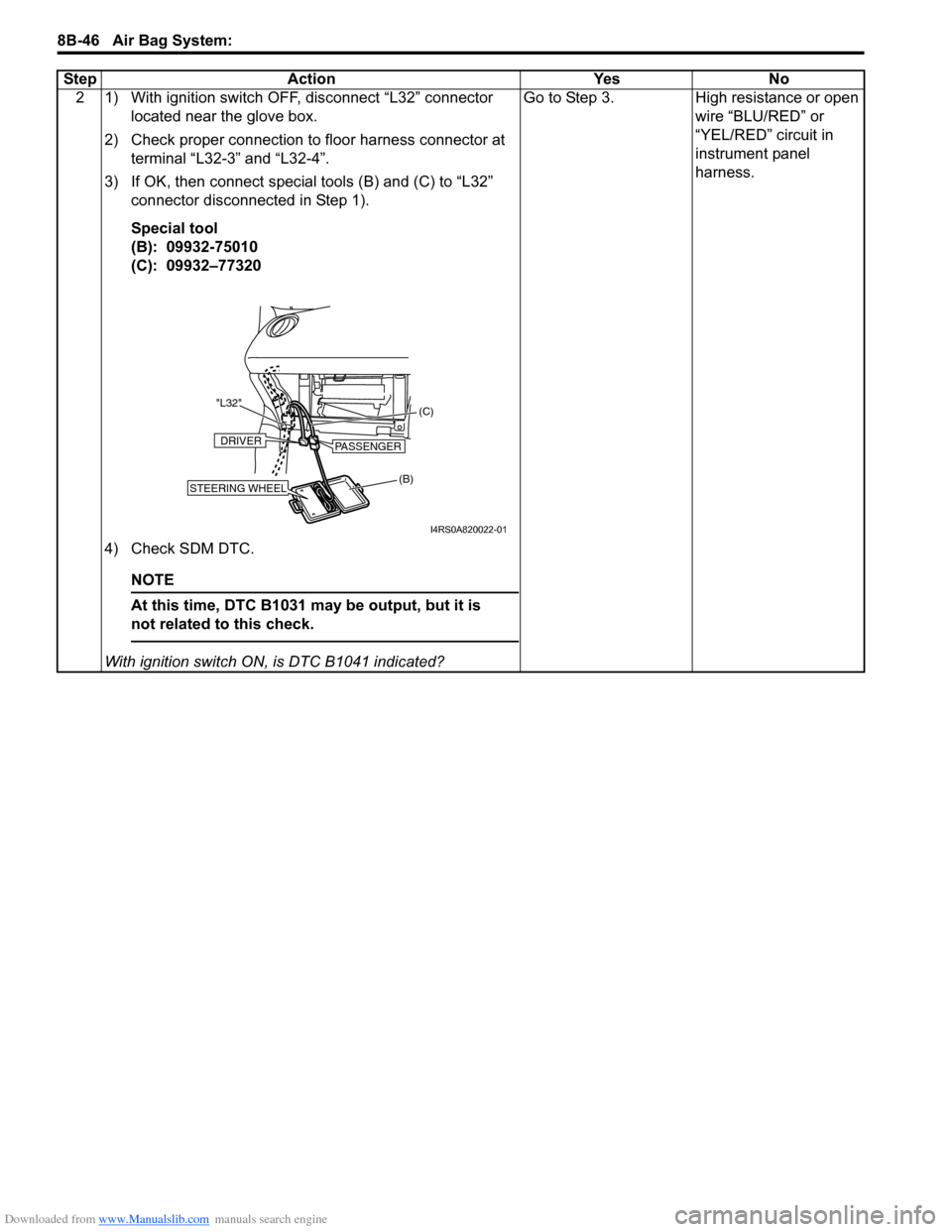
2 1) With ignition switch OFF, disconnect “L32” connector located near the glove box.
2) Check proper connection to floor harness connector at terminal “L32-3” and “L32-4”.
3) If OK, then connect special tools (B) and (C) to “L32” connector disconnected in Step 1).
Special tool
(B): 09932-75010
(C): 09932–77320
4) Check SDM DTC.
NOTE
At this time, DTC B1031 ma y be output, but it is
not related to this check.
With ignition switch ON , is DTC B1041 indicated? Go to Step 3. High resistance or open
wire “BLU/RED” or
“YEL/RED” circuit in
instrument panel
harness.
Step Action Yes No
(B) (C)
"L32"STEERING WHEEL
DRIVERPASSENGER
I4RS0A820022-01
Page 1087 of 1496
Downloaded from www.Manualslib.com manuals search engine Air Bag System: 8B-49
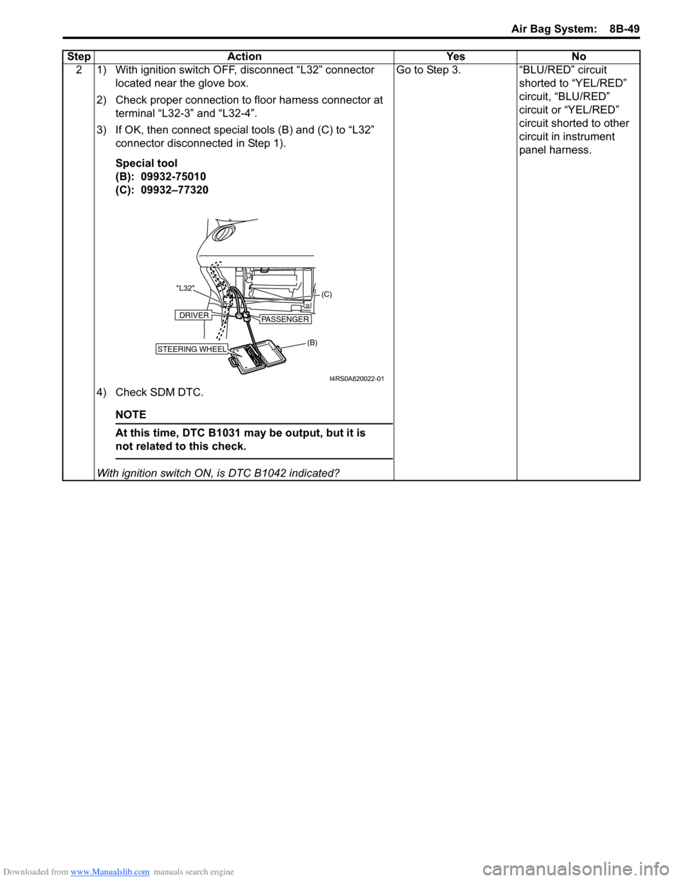
2 1) With ignition switch OFF, disconnect “L32” connector located near the glove box.
2) Check proper connection to floor harness connector at terminal “L32-3” and “L32-4”.
3) If OK, then connect special tools (B) and (C) to “L32” connector disconnected in Step 1).
Special tool
(B): 09932-75010
(C): 09932–77320
4) Check SDM DTC.
NOTE
At this time, DTC B1031 ma y be output, but it is
not related to this check.
With ignition switch ON , is DTC B1042 indicated? Go to Step 3. “BLU/RED” circuit
shorted to “YEL/RED”
circuit, “BLU/RED”
circuit or “YEL/RED”
circuit shorted to other
circuit in instrument
panel harness.
Step Action Yes No
(B)
(C)
"L32"STEERING WHEEL
DRIVERPASSENGER
I4RS0A820022-01
Page 1090 of 1496
Downloaded from www.Manualslib.com manuals search engine 8B-52 Air Bag System:
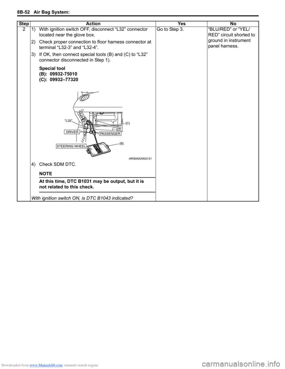
2 1) With ignition switch OFF, disconnect “L32” connector located near the glove box.
2) Check proper connection to floor harness connector at terminal “L32-3” and “L32-4”.
3) If OK, then connect special tools (B) and (C) to “L32” connector disconnected in Step 1).
Special tool
(B): 09932-75010
(C): 09932–77320
4) Check SDM DTC.
NOTE
At this time, DTC B1031 ma y be output, but it is
not related to this check.
With ignition switch ON , is DTC B1043 indicated? Go to Step 3. “BLU/RED” or “YEL/
RED” circuit shorted to
ground in instrument
panel harness.
Step Action Yes No
(B) (C)
"L32"STEERING WHEEL
DRIVERPASSENGER
I4RS0A820022-01