multi information display SUZUKI SWIFT 2005 2.G Service Workshop Manual
[x] Cancel search | Manufacturer: SUZUKI, Model Year: 2005, Model line: SWIFT, Model: SUZUKI SWIFT 2005 2.GPages: 1496, PDF Size: 34.44 MB
Page 77 of 1496
Downloaded from www.Manualslib.com manuals search engine Engine General Information and Diagnosis: 1A-27
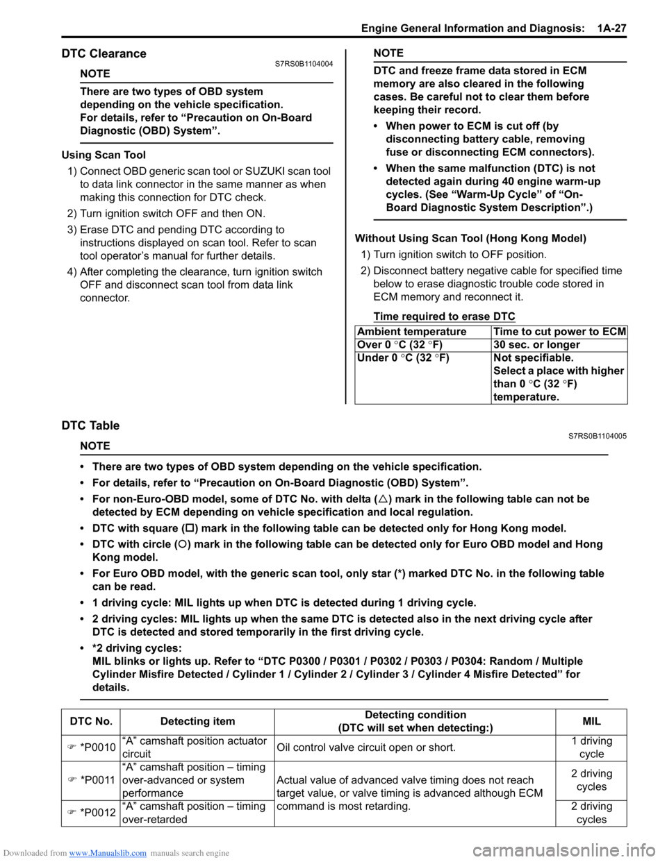
DTC ClearanceS7RS0B1104004
NOTE
There are two types of OBD system
depending on the vehicle specification.
For details, refer to “Precaution on On-Board
Diagnostic (OBD) System”.
Using Scan Tool1) Connect OBD generic scan to ol or SUZUKI scan tool
to data link connector in the same manner as when
making this connection for DTC check.
2) Turn ignition switch OFF and then ON.
3) Erase DTC and pending DTC according to instructions displayed on scan tool. Refer to scan
tool operator’s manual for further details.
4) After completing the clear ance, turn ignition switch
OFF and disconnect scan tool from data link
connector.
NOTE
DTC and freeze frame data stored in ECM
memory are also cleared in the following
cases. Be careful not to clear them before
keeping their record.
• When power to ECM is cut off (by disconnecting battery cable, removing
fuse or disconnecting ECM connectors).
• When the same malfunction (DTC) is not detected again during 40 engine warm-up
cycles. (See “Warm-Up Cycle” of “On-
Board Diagnostic System Description”.)
Without Using Scan Tool (Hong Kong Model)
1) Turn ignition switch to OFF position.
2) Disconnect battery negative cable for specified time below to erase diagnostic trouble code stored in
ECM memory and reconnect it.
Time required to erase DTC
DTC TableS7RS0B1104005
NOTE
• There are two types of OBD system depending on the vehicle specification.
• For details, refer to “Precaution on On-Board Diagnostic (OBD) System”.
• For non-Euro-OBD model, some of DTC No. with delta ( �U) mark in the following table can not be
detected by ECM depending on vehicl e specification and local regulation.
• DTC with square ( �†) mark in the following table can be detected only for Hong Kong model.
• DTC with circle ( �{) mark in the following table can be detected only for Euro OBD model and Hong
Kong model.
• For Euro OBD model, with the generic scan tool, onl y star (*) marked DTC No. in the following table
can be read.
• 1 driving cycle: MIL lights up when DTC is detected during 1 driving cycle.
• 2 driving cycles: MIL lights up when the same DTC is detected also in the next driving cycle after DTC is detected and stored temporarily in the first driving cycle.
• *2 driving cycles: MIL blinks or lights up. Refer to “DTC P0300 / P0301 / P0302 / P0303 / P0304: Random / Multiple
Cylinder Misfire Detected / Cylinder 1 / Cylinder 2 / Cylinder 3 / Cylinder 4 Misfire Detected” for
details.
Ambient temperature Time to cut power to ECM
Over 0 °C (32 ° F) 30 sec. or longer
Under 0 °C (32 °F) Not specifiable.
Select a place with higher
than 0 °C (32 °F)
temperature.
DTC No. Detecting item Detecting condition
(DTC will set when detecting:) MIL
�) *P0010 “A” camshaft position actuator
circuit Oil control valve circuit open or short. 1 driving
cycle
�) *P0011 “A” camshaft position – timing
over-advanced or system
performance Actual value of advanced va
lve timing does not reach
target value, or valve timi ng is advanced although ECM
command is most retarding. 2 driving
cycles
�) *P0012 “A” camshaft position – timing
over-retarded 2 driving
cycles
Page 85 of 1496
Downloaded from www.Manualslib.com manuals search engine Engine General Information and Diagnosis: 1A-35
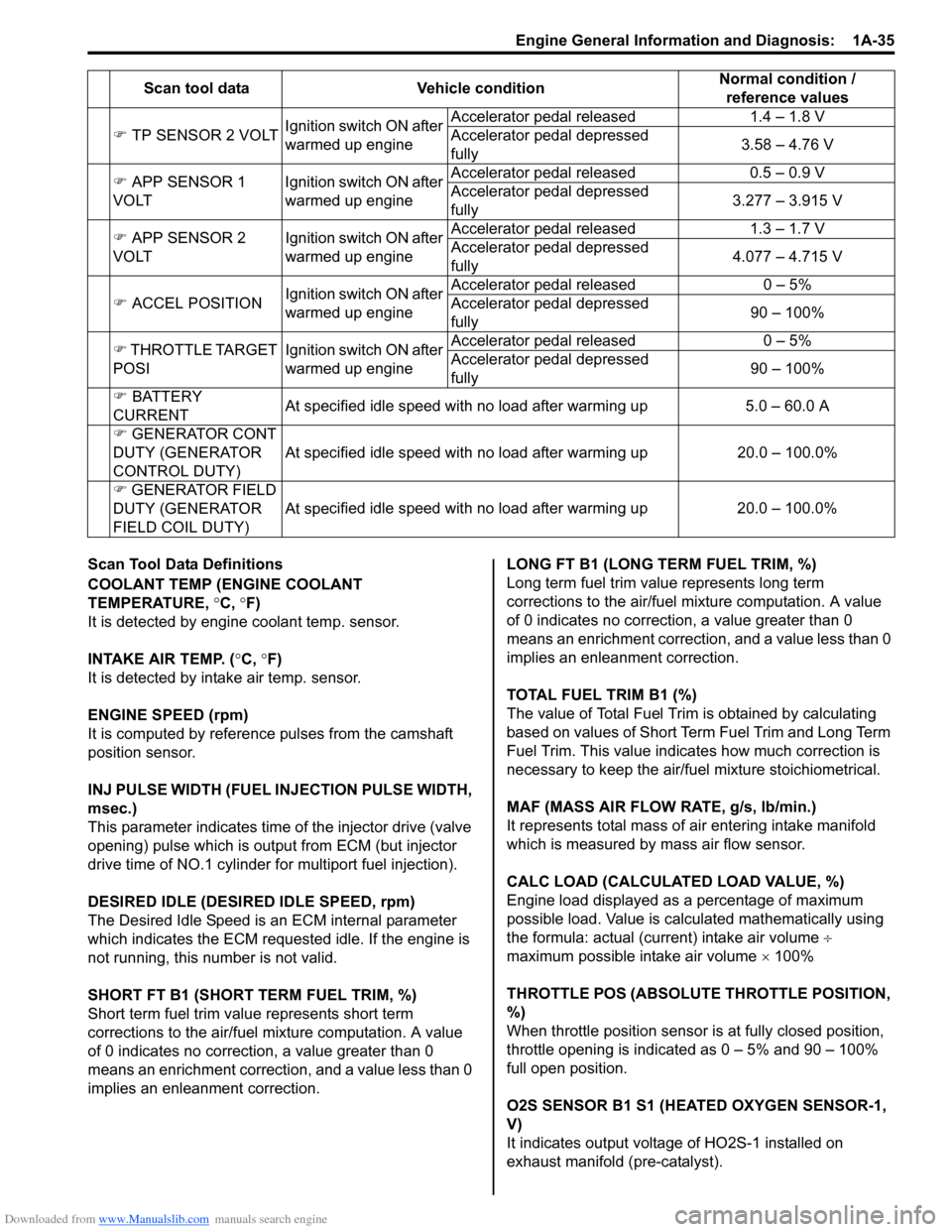
Scan Tool Data Definitions
COOLANT TEMP (ENGINE COOLANT
TEMPERATURE, °C, °F)
It is detected by engine coolant temp. sensor.
INTAKE AIR TEMP. ( °C, °F)
It is detected by intake air temp. sensor.
ENGINE SPEED (rpm)
It is computed by reference pulses from the camshaft
position sensor.
INJ PULSE WIDTH (FUEL INJECTION PULSE WIDTH,
msec.)
This parameter indicates time of the injector drive (valve
opening) pulse which is output from ECM (but injector
drive time of NO.1 cylinder fo r multiport fuel injection).
DESIRED IDLE (DESIRED IDLE SPEED, rpm)
The Desired Idle Speed is an ECM internal parameter
which indicates the ECM requested idle. If the engine is
not running, this number is not valid.
SHORT FT B1 (SHORT TERM FUEL TRIM, %)
Short term fuel trim valu e represents short term
corrections to the air/fuel mixture computation. A value
of 0 indicates no correction, a value greater than 0
means an enrichment correction, and a value less than 0
implies an enleanment correction. LONG FT B1 (LONG TERM FUEL TRIM, %)
Long term fuel trim value represents long term
corrections to the air/fuel mixture computation. A value
of 0 indicates no correction, a value greater than 0
means an enrichment correction, and a value less than 0
implies an enleanment correction.
TOTAL FUEL TRIM B1 (%)
The value of Total Fuel Trim is obtained by calculating
based on values of Short Term Fuel Trim and Long Term
Fuel Trim. This value indica
tes how much correction is
necessary to keep the air/fuel mixture stoichiometrical.
MAF (MASS AIR FLOW RATE, g/s, lb/min.)
It represents total mass of air entering intake manifold
which is measured by mass air flow sensor.
CALC LOAD (CALCULATED LOAD VALUE, %)
Engine load displayed as a percentage of maximum
possible load. Value is calculated mathematically using
the formula: actual (current) intake air volume ÷
maximum possible intake air volume × 100%
THROTTLE POS (ABSOLUTE THROTTLE POSITION,
%)
When throttle position sensor is at fully closed position,
throttle opening is indicated as 0 – 5% and 90 – 100%
full open position.
O2S SENSOR B1 S1 (HEA TED OXYGEN SENSOR-1,
V)
It indicates output voltage of HO2S-1 installed on
exhaust manifold (pre-catalyst).
�)
TP SENSOR 2 VOLT Ignition switch ON after
warmed up engine Accelerator pedal released
1.4 – 1.8 V
Accelerator pedal depressed
fully 3.58 – 4.76 V
�) APP SENSOR 1
VOLT Ignition switch ON after
warmed up engineAccelerator pedal released
0.5 – 0.9 V
Accelerator pedal depressed
fully 3.277 – 3.915 V
�) APP SENSOR 2
VOLT Ignition switch ON after
warmed up engineAccelerator pedal released
1.3 – 1.7 V
Accelerator pedal depressed
fully 4.077 – 4.715 V
�) ACCEL POSITION Ignition switch ON after
warmed up engine Accelerator pedal released
0 – 5%
Accelerator pedal depressed
fully 90 – 100%
�) THROTTLE TARGET
POSI Ignition switch ON after
warmed up engineAccelerator pedal released
0 – 5%
Accelerator pedal depressed
fully 90 – 100%
�) BATTERY
CURRENT At specified idle speed with no load after warming up
5.0 – 60.0 A
�) GENERATOR CONT
DUTY (GENERATOR
CONTROL DUTY) At specified idle speed with no load after warming up
20.0 – 100.0%
�) GENERATOR FIELD
DUTY (GENERATOR
FIELD COIL DUTY) At spe
cified idle speed with no load after warming up
20.0 – 100.0%
Scan tool data
Vehicle condition Normal condition /
reference values
Page 1167 of 1496

Downloaded from www.Manualslib.com manuals search engine Table of Contents 9- i
9
Section 9
CONTENTS
Body, Cab and Accessories
Precautions ................................................. 9-1
Precautions............................................................. 9-1
Precautions on Body, Cab and Accessories ......... 9-1
Precautions for Body Service ................................ 9-1
Fastener Caution for Body Service ....................... 9-1
Wiring Systems............... ......................... 9A-1
Precautions........................................................... 9A-1
Cautions in Body Electrical System Servicing..... 9A-1
General Description ............................................. 9A-1 Abbreviations ...................................................... 9A-1
Wire / Connector Color Sy mbols ......................... 9A-1
Symbols and Marks ............................................ 9A-2
How to Read Connector Layout Diagram ........... 9A-4
How to Read Connector Codes and Terminal Nos.................................................................... 9A-5
How to Read Ground Point ................................. 9A-7
How to Read Power Supply Diagram.................. 9A-8
How to Read System Circuit Diagram................. 9A-8
Connector Layout Diagram . .............................. 9A-10
Connector Layout Diagram ............................... 9A-10
Engine Compartment .......... .............................. 9A-10
Instrument Panel ............................................... 9A-16
Door, Roof......................................................... 9A-20
Floor .................................................................. 9A-23
Rear .................................................................. 9A-29
Ground Point ...................................................... 9A-30 Ground (earth) Point ......................................... 9A-30
Power Supply Diagram ........ .............................. 9A-31
Power Supply Diagram ....... .............................. 9A-31
Fuses and the Protected Parts ......................... 9A-33
Fuses in Main Fuse Box (RHD) ........................ 9A-33
Fuses in Main Fuse Box (LHD) ......................... 9A-33
Individual Circuit Fuse Box No. 1 ...................... 9A-34
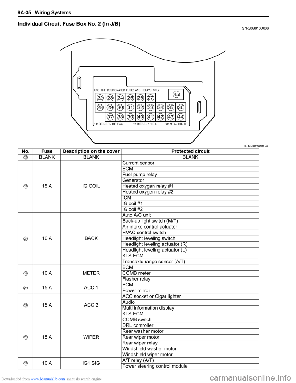
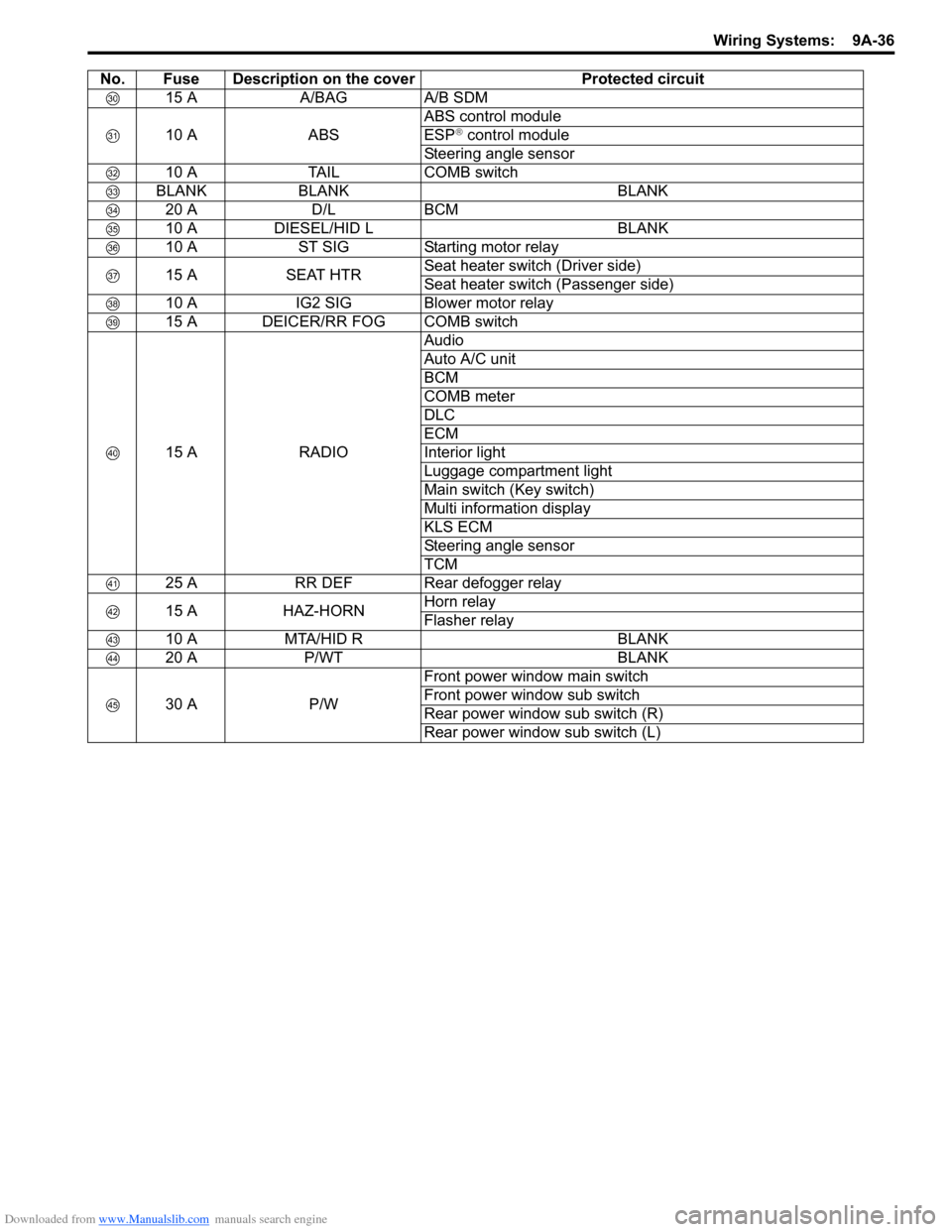
Individual Circuit Fuse Box No. 2 (In J/B) ......... 9A-35
Junction Block (J/B) Connector / Fuse Layout .. 9A-37
Junction Block Inner Circuit (Overview) ............ 9A-38
Junction Block Inner Circuit (Detail) .................. 9A-40
System Circuit Diagram... .................................. 9A-45
System Circuit Diagram .. .................................. 9A-45
A-1 Cranking System Circ uit Diagram .............. 9A-46
A-2 Charging System Circu it Diagram .............. 9A-47
A-3 Ignition System Circu it Diagram ................. 9A-48
A-4 Cooling System Circuit Diagram................. 9A-49 A-5 Engine and A/C Control System Circuit
Diagram........................................................... 9A-50
A-6 A/T Control System Circuit Diagram........... 9A-55
A-7 Immobilizer System Circuit Diagram .......... 9A-57
A-8 Body Control System Circuit Diagram ........ 9A-58
B-1 Windshield Wiper and Washer Circuit Diagram........................................................... 9A-62
B-2 Rear Wiper and Washer Circuit Diagram ... 9A-63
B-3 Rear Defogger Circuit Diagram .................. 9A-64
B-4 Power Window Circuit Diagram .................. 9A-65
B-5 Power Door Lock Circu it Diagram .............. 9A-67
B-6 Power Mirror Circuit Diagram ..................... 9A-69
B-7 Horn Circuit Diagram .................................. 9A-70
B-8 Seat Heater Circuit Diagram....................... 9A-71
B-9 Keyless Start System Circuit Diagram........ 9A-72
C-1 Combination Mete r Circuit Diagram
(Meter)............................................................. 9A-73
C-2 Combination Mete r Circuit Diagram
(Indicator) ........................................................ 9A-74
C-3 Combination Mete r Circuit Diagram
(Warning Light)................................................ 9A-75
D-1 Headlight System Circuit Diagram ............. 9A-77
D-2 Position, Tail and Licence Plate Light System Circuit Diagram .................................. 9A-79
D-3 Front Fog Light System Circuit Diagram .... 9A-80
D-4 Illumination Light System Circuit Diagram .. 9A-81
D-5 Interior Light System Circuit Diagram......... 9A-82
D-6 Turn Signal and Hazard Warning Light System Circuit Diagram .................................. 9A-83
D-7 Brake Light System Circuit Diagram .......... 9A-85
D-8 Back-Up Light System Circuit Diagram ...... 9A-86
D-9 Headlight Beam Leveling System Circuit Diagram........................................................... 9A-87
D-10 Rear Fog Light Circuit Diagram ................ 9A-88
E-1 Heater System Circuit Diagram .................. 9A-89
E-2 Auto A/C System Circuit Diagram .............. 9A-91
F-1 Air-Bag System Circuit Diagram ................. 9A-93
F-2 Anti-Lock Brake System Circuit Diagram.... 9A-95
F-3 Electronic Stab ility Program System
Circuit Diagram .................. ............................. 9A-97
F-4 Power Steering System Circuit Diagram .... 9A-99
G-1 Audio System Circuit Diagram ................. 9A-101
G-2 Multi Information Display / Accessory Socket System Circuit Diagram .................... 9A-102
List of Connector .............................................9A-103
Page 1189 of 1496
Downloaded from www.Manualslib.com manuals search engine Wiring Systems: 9A-18
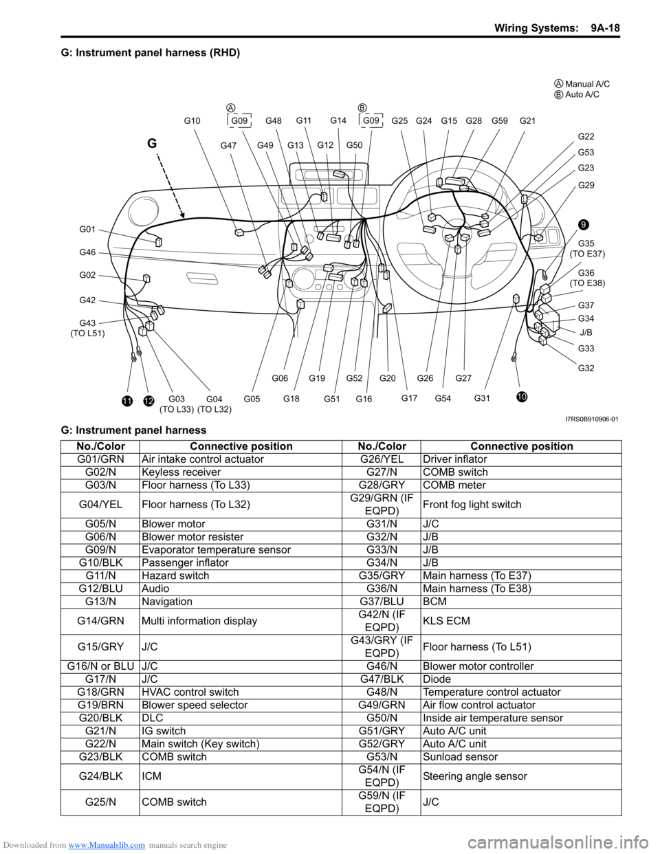
G: Instrument panel harness (RHD)
G: Instrument panel harness
J/B
9
10
G33
G32 G34 G35
(TO E37)
G36
(TO E38)
G31 G29
G23
G53
G22
G21
G28G59
G20G52G27
G54
G261112G03
(TO L33)G04
(TO L32)
G46
G01
G02
G42
G43
(TO L51) G10
G47
G11
G13G49
G14
G09G25 G24G15
G12G50
G48
G17
G16G51
G19
G18
G06
G05
G
G09
G37
A
BManual A/C
Auto A/C
AB
I7RS0B910906-01
No./Color Connective position No./ColorConnective position
G01/GRN Air intake control ac tuatorG26/YEL Driver inflator
G02/N Keyless receiver G27/N COMB switch
G03/N Floor harness (To L33) G28/GRY COMB meter
G04/YEL Floor harness (To L32) G29/GRN (IF
EQPD) Front fog light switch
G05/N Blower motor G31/N J/C
G06/N Blower motor resister G32/N J/B
G09/N Evaporator temperature sensor G33/N J/B
G10/BLK Passenger inflator G34/N J/B
G11/N Hazard switch G35/GRY Main harness (To E37)
G12/BLU Audio G36/N Main harness (To E38)
G13/N Navigation G37/BLU BCM
G14/GRN Multi information display G42/N (IF
EQPD) KLS ECM
G15/GRY J/C G43/GRY (IF
EQPD) Floor harness (To L51)
G16/N or BLU J/C G46/N Blower motor controller
G17/N J/C G47/BLK Diode
G18/GRN HVAC control switch G48/N Temperature control actuator
G19/BRN Blower speed selector G49/GRN Air flow control actuator
G20/BLK DLC G50/N Inside air temperature sensor
G21/N IG switch G51/GRY Auto A/C unit
G22/N Main switch (Key switch) G52/GRY Auto A/C unit
G23/BLK COMB switch G53/N Sunload sensor
G24/BLK ICM G54/N (IF
EQPD) Steering angle sensor
G25/N COMB switch G59/N (IF
EQPD) J/C
Page 1190 of 1496
Downloaded from www.Manualslib.com manuals search engine 9A-19 Wiring Systems:
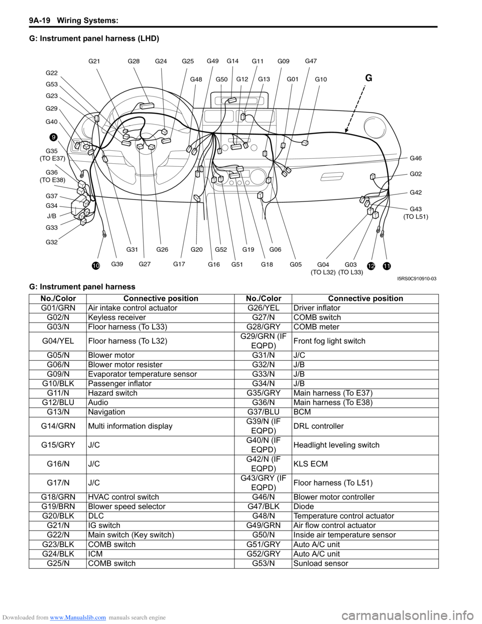
G: Instrument panel harness (LHD)
G: Instrument panel harness
J/B
9
10
G33
G32 G34 G35
(TO E37)
G36
(TO E38)
G29
G40
G23
G53
G22 G21
G28
G20G52
G27G39 G26
G31
1112G03
(TO L33)G04
(TO L32)
G46
G02
G42
G43
(TO L51)
G10
G47G11
G13G01
G14
G49
G50G48
G25
G24
G12
G17
G16G51G19
G18
G06
G05
G
G09
G37
I5RS0C910910-03
No./Color Connective position No./ColorConnective position
G01/GRN Air intake control ac tuatorG26/YEL Driver inflator
G02/N Keyless receiver G27/N COMB switch
G03/N Floor harness (To L33) G28/GRY COMB meter
G04/YEL Floor harness (To L32) G29/GRN (IF
EQPD) Front fog light switch
G05/N Blower motor G31/N J/C
G06/N Blower motor resister G32/N J/B
G09/N Evaporator temperature sensor G33/N J/B
G10/BLK Passenger inflator G34/N J/B
G11/N Hazard switch G35/GRY Main harness (To E37)
G12/BLU Audio G36/N Main harness (To E38)
G13/N Navigation G37/BLU BCM
G14/GRN Multi information display G39/N (IF
EQPD) DRL controller
G15/GRY J/C G40/N (IF
EQPD) Headlight leveling switch
G16/N J/C G42/N (IF
EQPD) KLS ECM
G17/N J/C G43/GRY (IF
EQPD) Floor harness (To L51)
G18/GRN HVAC control switch G46/N Blower motor controller
G19/BRN Blower speed selector G47/BLK Diode
G20/BLK DLC G48/N Temperature control actuator
G21/N IG switch G49/GRN Air flow control actuator
G22/N Main switch (Key switch) G50/N Inside air temperature sensor
G23/BLK COMB switch G51/GRY Auto A/C unit
G24/BLK ICM G52/GRY Auto A/C unit
G25/N COMB switch G53/N Sunload sensor
Page 1206 of 1496
Downloaded from www.Manualslib.com manuals search engine 9A-35 Wiring Systems:
Individual Circuit Fuse Box No. 2 (In J/B)S7RS0B910D006
22
28
23
29
37
24
30
38
25
31
39
26
32
40
27
33
41
34
42
35
43
36
44
45USE THE DESINGNATED FUSES AND RELAYS ONLY.
*1: DEICER / RR FOG *2: DIESEL / HID L *3: MTA / HID R
I5RS0B910919-02
No. Fuse Description on the coverProtected circuit
BLANK BLANK BLANK
15 A IG COILCurrent sensor
ECM
Fuel pump relay
Generator
Heated oxygen relay #1
Heated oxygen relay #2
ICM
IG coil #1
IG coil #2
10 A BACKAuto A/C unit
Back-up light switch (M/T)
Air intake control actuator
HVAC control switch
Headlight leveling switch
Headlight leveling actuator (R)
Headlight leveling actuator (L)
KLS ECM
Transaxle range sensor (A/T)
10 A METERBCM
COMB meter
Flasher relay
15 A ACC 1BCM
Power mirror
15 A ACC 2ACC socket or Cigar lighter
Audio
Multi information display
KLS ECM
15 A WIPERCOMB switch
DRL controller
Rear washer motor
Rear wiper motor
Rear wiper relay
Windshield washer motor
Windshield wiper motor
10 A IG1 SIGA/T relay (A/T)
Power steering control module
Page 1207 of 1496
Downloaded from www.Manualslib.com manuals search engine Wiring Systems: 9A-36
15 AA/BAG A/B SDM
10 A ABSABS control module
ESP
® control module
Steering angle sensor
10 A TAIL COMB switch
BLANK BLANK BLANK 20 A D/L BCM
10 A DIESEL/HID L BLANK
10 A ST SIG Starting motor relay
15 A SEAT HTR Seat heater switch (Driver side)
Seat heater switch (Passenger side)
10 A IG2 SIG Blower motor relay
15 A DEICER/RR FOG COMB switch
15 A RADIO Audio
Auto A/C unit
BCM
COMB meter
DLC
ECM
Interior light
Luggage compartment light
Main switch (Key switch)
Multi information display
KLS ECM
Steering angle sensor
TCM
25 A RR DEF Rear defogger relay
15 A HAZ-HORN Horn relay
Flasher relay
10 A MTA/HID R BLANK
20 A P/WT BLANK
30 A P/W Front power window main switch
Front power window sub switch
Rear power window sub switch (R)
Rear power window sub switch (L)
No. Fuse Description on the cover Protected circuit
Page 1216 of 1496

Downloaded from www.Manualslib.com manuals search engine 9A-45 Wiring Systems:
System Circuit Diagram
System Circuit DiagramS7RS0B910E001
Refer to “A-1 Cranking System Circuit Diagram”.
Refer to “A-2 Charging System Circuit Diagram”.
Refer to “A-3 Ignition System Circuit Diagram”.
Refer to “A-4 Cooling System Circuit Diagram”.
Refer to “A-5 Engine and A/C Control System Circuit Diagram”.
Refer to “A-6 A/T Control System Circuit Diagram”.
Refer to “A-7 Immobilizer System Circuit Diagram”.
Refer to “A-8 Body Control System Circuit Diagram”.
Refer to “B-1 Windshield Wiper and Washer Circuit Diagram”.
Refer to “B-2 Rear Wiper and Washer Circuit Diagram”.
Refer to “B-3 Rear Defogger Circuit Diagram”.
Refer to “B-4 Power Window Circuit Diagram”.
Refer to “B-5 Power Door Lock Circuit Diagram”.
Refer to “B-6 Power Mi rror Circuit Diagram”.
Refer to “B-7 Horn Circuit Diagram”.
Refer to “B-8 Seat Heater Circuit Diagram”.
Refer to “B-9 Keyless Star t System Circuit Diagram”.
Refer to “C-1 Combination Me ter Circuit Diagram (Meter)”.
Refer to “C-2 Combination Mete r Circuit Diagram (Indicator)”.
Refer to “C-3 Combination Meter Circuit Diagram (Warning Light)”.
Refer to “D-1 Headlight System Circuit Diagram”.
Refer to “D-2 Position, Tail and Licence Plate Light System Circuit Diagram”.
Refer to “D-3 Front Fog Light System Circuit Diagram”.
Refer to “D-4 Illumination Light System Circuit Diagram”.
Refer to “D-5 Interior Li ght System Circuit Diagram”.
Refer to “D-6 Turn Signal and Hazard Warning Light System Circuit Diagram”.
Refer to “D-7 Brake Light System Circuit Diagram”.
Refer to “D-8 Back-Up Light System Circuit Diagram”.
Refer to “D-9 Headlight Beam Leveling System Circuit Diagram”.
Refer to “D-10 Rear Fog Light Circuit Diagram”.
Refer to “E-1 Heater System Circuit Diagram”.
Refer to “E-2 Auto A/C System Circuit Diagram”.
Refer to “F-1 Air-Bag System Circuit Diagram”.
Refer to “F-2 Anti-Lock Brake System Circuit Diagram”.
Refer to “F-3 Electronic Stabilit y Program System Circuit Diagram”.
Refer to “F-4 Power Steeri ng System Circuit Diagram”.
Refer to “G-1 Audio Sy stem Circuit Diagram”.
Refer to “G-2 Multi Information Display / Accessory Socket System Circuit Diagram”.
Page 1232 of 1496
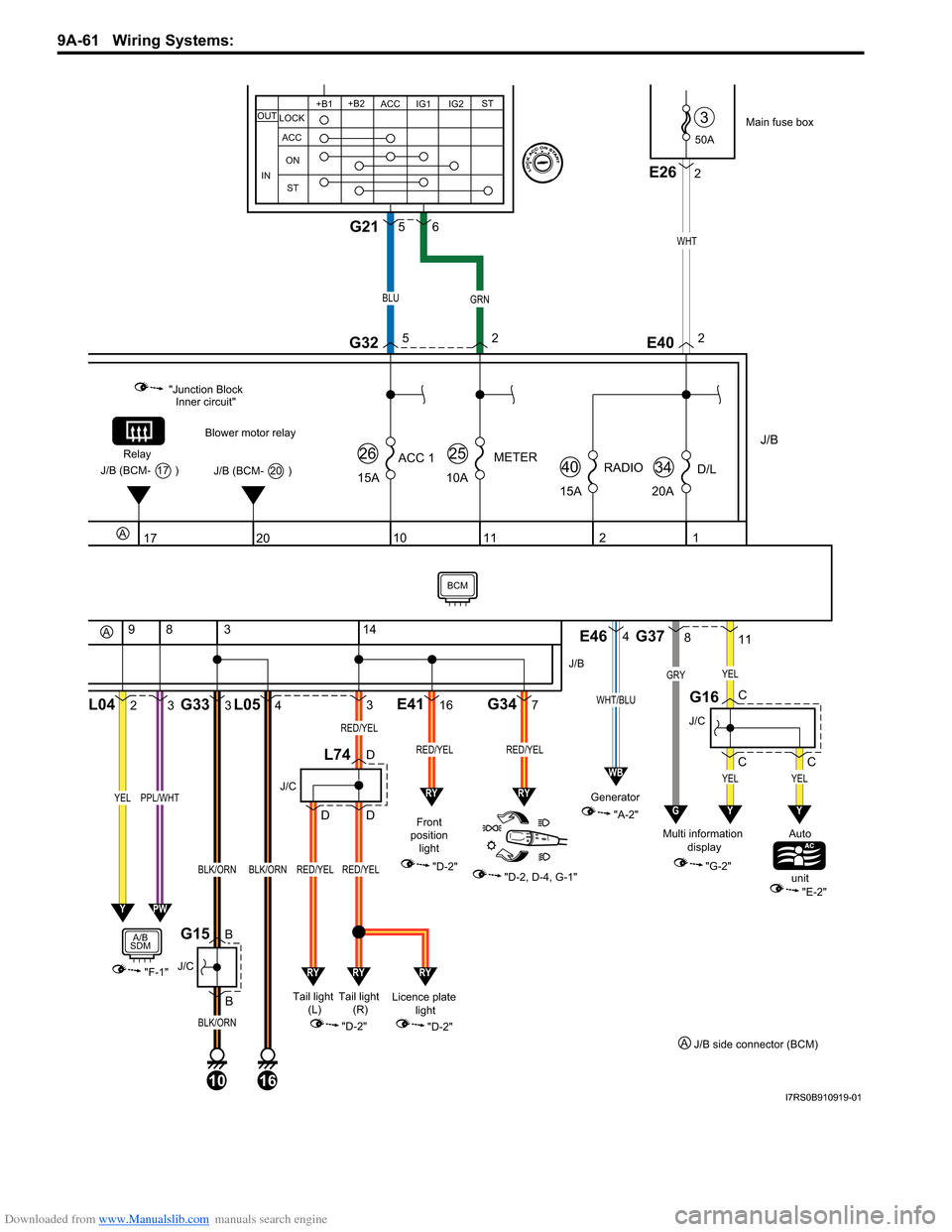
Downloaded from www.Manualslib.com manuals search engine 9A-61 Wiring Systems:
50A
3
J/B
15ARADIO
40
2
15A
ACC 1
26
10
1
20AD/L
34
11
10A
METER
25
Main fuse box
WHT
E402
20
Blower motor relay
"Junction Block Inner circuit"
Relay
J/B (BCM- 20 )J/B (BCM- 17 )
17
2L04
9
3
83
B BG33
3
4L05
10
J/C
G15
BLK/ORN
BLK/ORN
16
BLK/ORN
"F-1"
YELPPL/WHT
A/B
SDM
14
316E417G34
Front
position light
"D-2"
"D-2, D-4, G-1"
J/B
RED/YELRED/YEL
J/C
L74D
DD
Licence plate light
"D-2"
YPW
"A-2"
Generator
E464
WHT/BLU
WB
RYRY
RYRYRY
Tail light
(R)
Tail light
(L)
"D-2"
RED/YEL
RED/YEL
RED/YEL
811
C CG37
J/C
G16
YEL
GRYYEL
GY
C
YEL
Y
"G-2"
Multi information
display Auto
unit
"E-2"
A
A
J/C
2E26
+B1
LOCK
ACC
ON
ST ACC IG1 IG2
STOUT
IN
+B2
BLUGRN
G3252
56G21
J/B side connector (BCM)
A
BCM
I7RS0B910919-01
Page 1252 of 1496
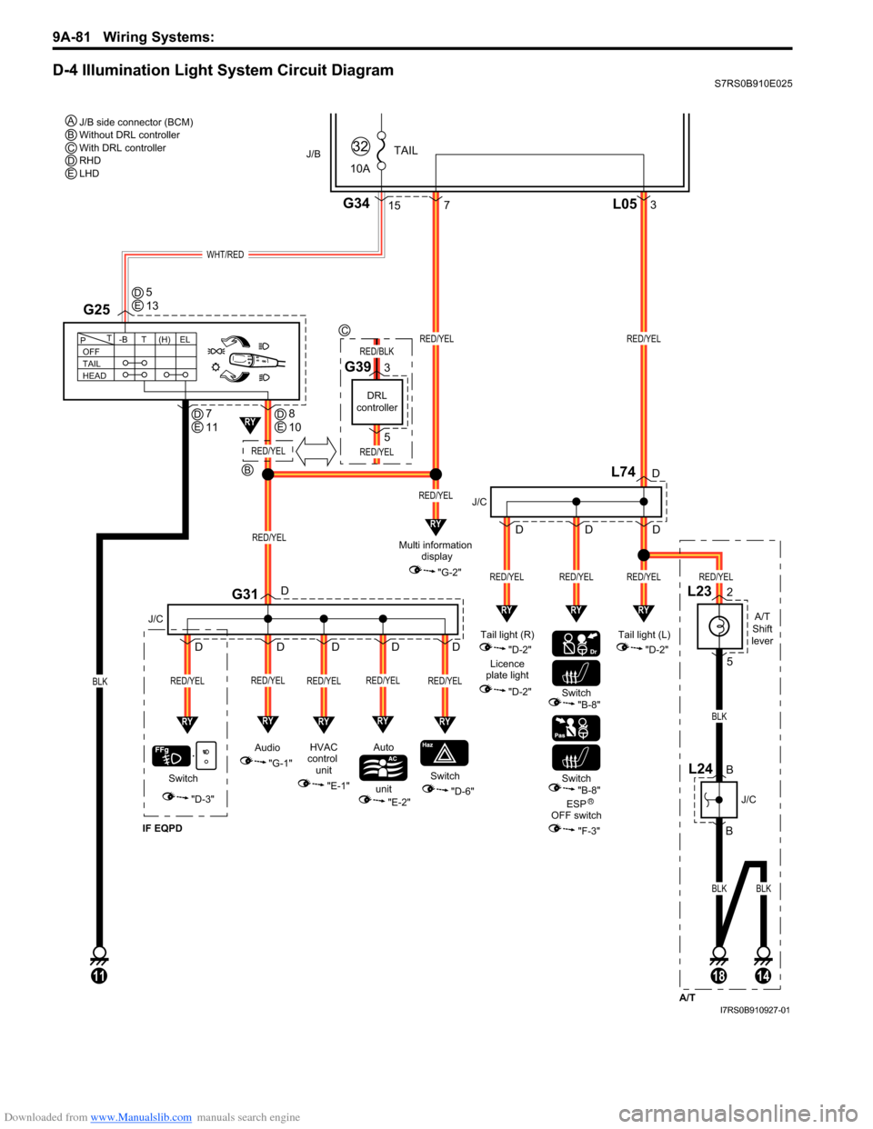
Downloaded from www.Manualslib.com manuals search engine 9A-81 Wiring Systems:
D-4 Illumination Light System Circuit DiagramS7RS0B910E025
WHT/RED
A/T
Shift
lever
L23
L742
5
BLK
BLKBLK
10A
TAIL
32J/B
15G34
BLK
G25
111814
A/T
B
B
J/C
L24
RED/YEL
RED/YEL
L053
"D-3"
IF EQPD
RY
Switch
J/C J/C
G31
RED/YEL
RY
RED/YEL
Switch
RY
RED/YEL
HVAC
control unit Auto
unit
"E-1"
"E-2""D-6"
OFF
TAIL
HEAD -BT
T
P(H) ELRED/YEL
7
RY
RED/YEL
Audio
"G-1"
D
D
D
D
D
D
D
RY
RED/YEL
D
D
RY
RY
RED/YEL
Multi information
display
"G-2"RED/YEL
RED/YEL
RED/YEL
RY
Tail light (L) "D-2"
RED/YEL
RY
Tail light (R) "D-2"
Licence
plate light
"D-2"
J/B side connector (BCM)
Without DRL controller
With DRL controller
RHD
LHD
A
R
BCDE
Switch
"B-8"
Switch"B-8"
ESP
OFF switch
"F-3"
DE5
13
DE7
11DE
B
C
8
10
DRL
controller
G393
5
RED/YEL
RED/BLK
RED/YEL
D
RY
I7RS0B910927-01