passenger SUZUKI SWIFT 2005 2.G Service Workshop Manual
[x] Cancel search | Manufacturer: SUZUKI, Model Year: 2005, Model line: SWIFT, Model: SUZUKI SWIFT 2005 2.GPages: 1496, PDF Size: 34.44 MB
Page 2 of 1496
Downloaded from www.Manualslib.com manuals search engine IMPORTANT
WARNING/CAUTION/NOTE
Please read this manual and follow its instructions carefully. To emphasize special information, the words , and NOTE have special meanings. Pay specia l attention to the messages high-
lighted by these signal words.
The circle with a slash in this manual me ans “Don’t do this” or “Don’t let this happen”.
WARNING!CAUTION!
Indicates a potential hazard that could result in death or injury.
WARNING!
Indicates a potential hazard that could result in vehicle damage.
CAUTION!
NOTE:
Indicates special information to make main tenance easier or instructions clearer.
This service manual is intended for authorized Su zuki dealers and qualified service technicians only.
Inexperienced technicians or technicians without the proper tools and equipment may not be able to
properly perform the services described in this manual.
Improper repair may result in injury to the technician and may render the vehicle unsafe for the driver
and passengers.
WARNING!
For vehicles equipped with a Supplemental Restraint (Air Bag) System:
• Service on and around the air bag system components or wiring must be performed only by an authorized SUZUKI dealer. Refer to “Air Bag System Components and Wiring Location View” under
“General Description” in air bag system section in order to confirm whether you are performing ser-
vice on or near the air bag system components or wiring. Please observe all WARNINGS and “Ser-
vice Precautions” under “On-Vehicl e Service” in air bag system section before performing service
on or around the air bag system components or wiring. Failure to follow WARNINGS could result in
unintentional activation of the system or could re nder the system inoperative. Either of these two
conditions may result in severe injury.
If the air bag system and another vehicle system both need repair, Suzuki recommends that the air
bag system be repaired first, to help av oid unintended air bag system activation.
Do not modify the steering wheel, instrument pa nel or any other air bag system component on or
around air bag system components or wiring. Modi fications can adversely affect air bag system
performance and lead to injury.
If the vehicle will be exposed to temperatures over 93 °C (200 °F), for example, during a paint baking
process, remove the air bag system components, th at is air bag (inflator) modules, SDM and/or seat
belt with pretensioner, beforehand to avoid component damage or unintended activation.
WARNING!
Page 6 of 1496
Downloaded from www.Manualslib.com manuals search engine 00-1 Precautions:
Precautions
Precautions
Precautions
Precautions for Vehicles Equipped with a
Supplemental Restraint (Air Bag) System
S7RS0B0000001
WARNING!
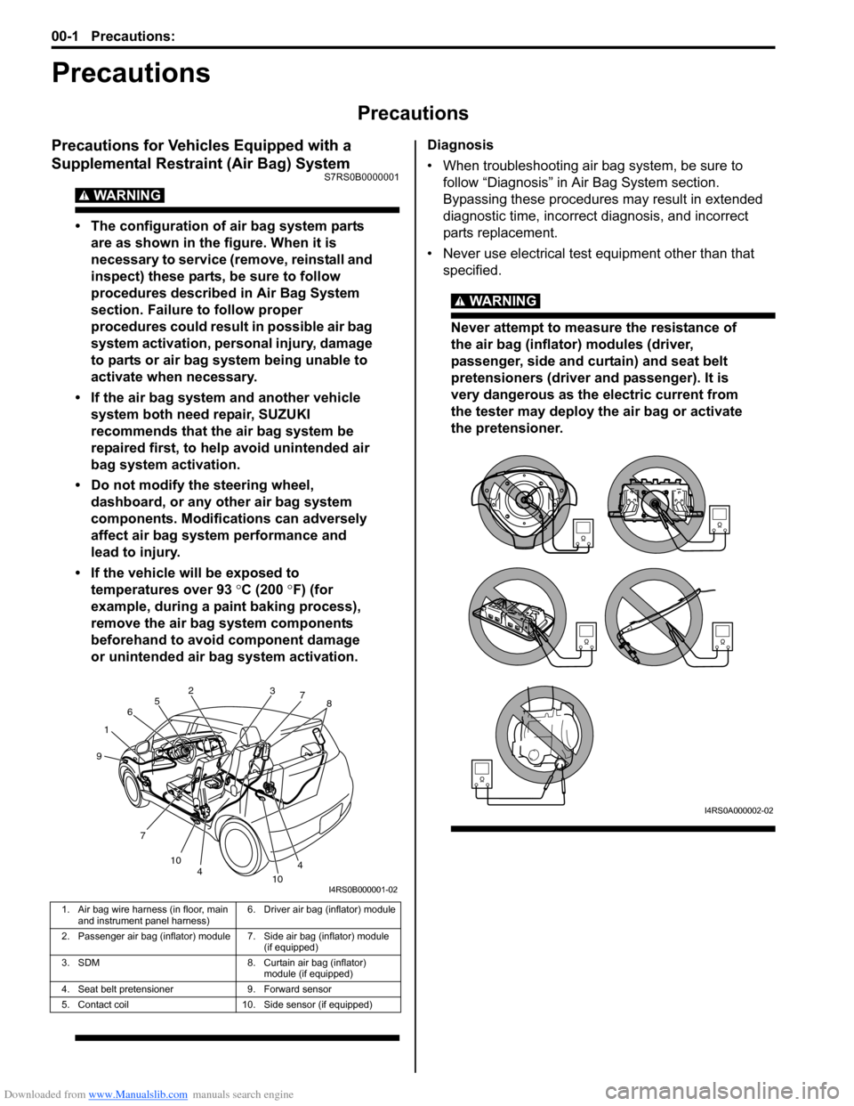
• The configuration of air bag system parts are as shown in the figure. When it is
necessary to service (remove, reinstall and
inspect) these parts, be sure to follow
procedures described in Air Bag System
section. Failure to follow proper
procedures could result in possible air bag
system activation, personal injury, damage
to parts or air bag system being unable to
activate when necessary.
• If the air bag system and another vehicle system both need repair, SUZUKI
recommends that the air bag system be
repaired first, to help avoid unintended air
bag system activation.
• Do not modify the steering wheel, dashboard, or any other air bag system
components. Modifications can adversely
affect air bag system performance and
lead to injury.
• If the vehicle will be exposed to temperatures over 93 °C (200 °F) (for
example, during a paint baking process),
remove the air bag system components
beforehand to avoid component damage
or unintended air bag system activation.
Diagnosis
• When troubleshooting air bag system, be sure to follow “Diagnosis” in Air Bag System section.
Bypassing these procedures may result in extended
diagnostic time, incorrect diagnosis, and incorrect
parts replacement.
• Never use electrical test equipment other than that specified.
WARNING!
Never attempt to measure the resistance of
the air bag (inflator) modules (driver,
passenger, side and curtain) and seat belt
pretensioners (driver and passenger). It is
very dangerous as the electric current from
the tester may deploy the air bag or activate
the pretensioner.
1. Air bag wire harness (in floor, main and instrument panel harness) 6. Driver air bag (inflator) module
2. Passenger air bag (inflator) module 7. Side air bag (inflator) module (if equipped)
3. SDM 8. Curtain air bag (inflator) module (if equipped)
4. Seat belt pretensioner 9. Forward sensor
5. Contact coil 10. Side sensor (if equipped)
1 2
3
4
4
5
6
7 7
8
9
10 10
I4RS0B000001-02
I4RS0A000002-02
Page 7 of 1496
Downloaded from www.Manualslib.com manuals search engine Precautions: 00-2
Servicing and Handling
WARNING!
Many of service procedures require
disconnection of “A/BAG” fuse and all air
bag (inflator) module(s) from initiator circuit
to avoid an accidental deployment.
Driver, Passenger, Side and Curtain Air Bag
(Inflator) Modules
• For handling and storage of a live air bag (inflator) module, select a place where the
ambient temperature below 65 °C (150 ° F),
without high humidity and away from
electric noise.
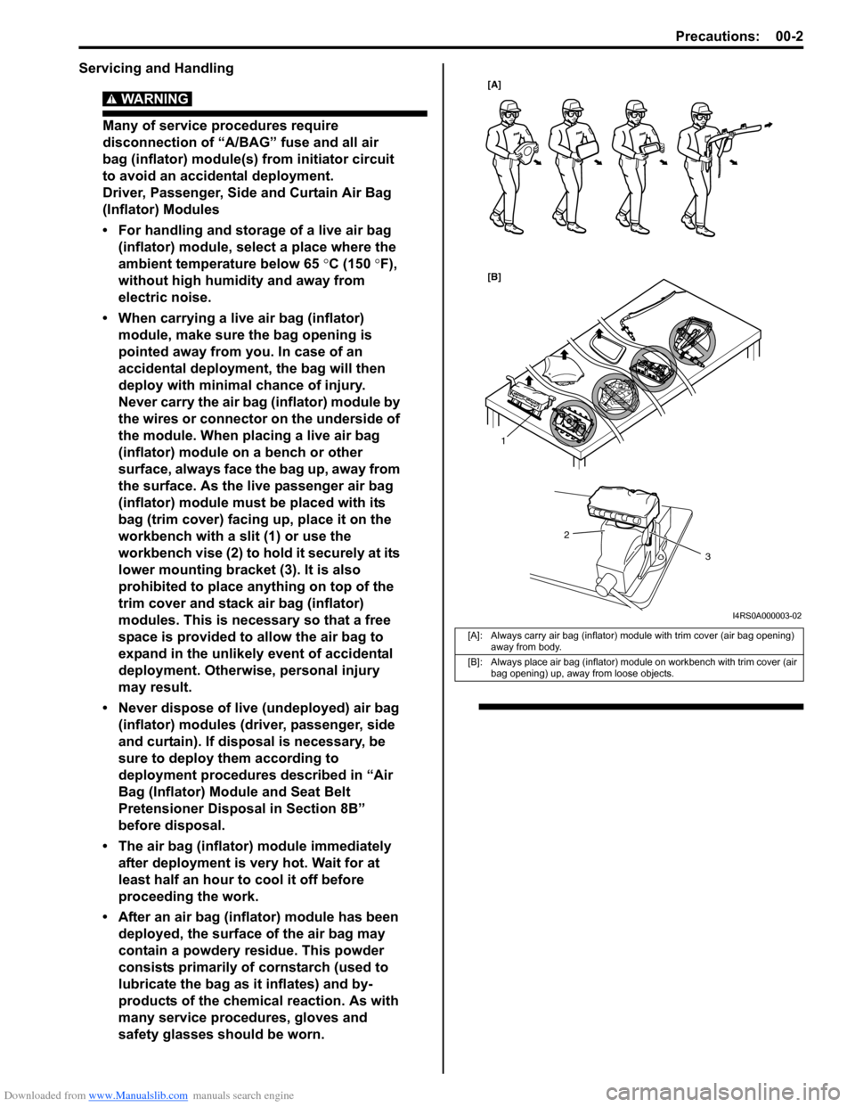
• When carrying a live air bag (inflator) module, make sure the bag opening is
pointed away from you. In case of an
accidental deployment, the bag will then
deploy with minimal chance of injury.
Never carry the air bag (inflator) module by
the wires or connector on the underside of
the module. When placing a live air bag
(inflator) module on a bench or other
surface, always face the bag up, away from
the surface. As the live passenger air bag
(inflator) module must be placed with its
bag (trim cover) facing up, place it on the
workbench with a slit (1) or use the
workbench vise (2) to hold it securely at its
lower mounting bracket (3). It is also
prohibited to place anything on top of the
trim cover and stack air bag (inflator)
modules. This is necessary so that a free
space is provided to allow the air bag to
expand in the unlikely event of accidental
deployment. Otherwise, personal injury
may result.
• Never dispose of live (undeployed) air bag (inflator) modules (driver, passenger, side
and curtain). If disposal is necessary, be
sure to deploy them according to
deployment procedures described in “Air
Bag (Inflator) Module and Seat Belt
Pretensioner Disposal in Section 8B”
before disposal.
• The air bag (inflator) module immediately
after deployment is very hot. Wait for at
least half an hour to cool it off before
proceeding the work.
• After an air bag (inflator) module has been deployed, the surface of the air bag may
contain a powdery residue. This powder
consists primarily of cornstarch (used to
lubricate the bag as it inflates) and by-
products of the chemical reaction. As with
many service procedures, gloves and
safety glasses should be worn.
[A]: Always carry air bag (inflator) module with trim cover (air bag opening) away from body.
[B]: Always place air bag (inflator) module on workbench with trim cover (air bag opening) up, away from loose objects.
1
2
3
[A]
[B]
I4RS0A000003-02
Page 8 of 1496
Downloaded from www.Manualslib.com manuals search engine 00-3 Precautions:
WARNING!
SDM
• For handling and storage of a SDM, select a place where the ambient temperature
below 65 °C (150 °F), without high humidity
and away from electric noise.
• During service procedures, be very careful when handling a Sensing and Diagnostic
Module (SDM). Never strike or jar the SDM.
• Never power up the air bag system when the SDM is not rigidly attached to the
vehicle. All SDM and mounting bracket
fasteners must be carefully torqued and
the arrow must be pointing toward the
front of the vehicle to ensure proper
operation of the air bag system.
The SDM could be activated when powered
while not rigidly att ached to the vehicle
which could cause deployment and result
in personal injury.
WARNING!
Driver and Passenger Seat Belt
Pretensioners
• For handling and storage of a live seat belt pretensioner, select a place where the
ambient temperature below 65 °C (150 ° F),
without high humidity and away from
electric noise.
• Never carry seat belt pretensioner by wire or connector of pretensioner. When
placing a live seat belt pretensioner on the
workbench or some place like that, never
put something on seat belt pretensioner.
Otherwise, personal injury may result.
• Never dispose of live (inactivated) seat belt pretensioners (drive and passenger). If
disposal is necessary, be sure to activate
them according to activation procedures
described in “Air Bag (Inflator) Module and
Seat Belt Pretensioner Disposal in Section
8B” before disposal.
• The seat belt pretensioner immediately after activation is very hot. Wait for at least
half an hour to cool it off before
proceeding the work.
• With many service procedures, gloves and safety glasses should be worn to prevent
any possible irritation of the skin or eyes.
• Even when the accident was light enough not to cause air bags to activate, be sure to inspect system
parts and other related parts according to instructions
under “Repair and Inspection Required after Accident
in Section 8B”.
• When servicing parts other than air bag system, if shocks may be applied to air bag system component
parts, remove those parts beforehand.
• When handling the air bag (inflator) modules (driver, passenger, side and curtain), seat belt pretensioners
(driver and passenger), forward sensor, side sensors
or SDM, be careful not to drop it or apply an impact to
it. If an excessive impact was applied, never attempt
disassembly or repair but replace it with a new one.
• When grease, cleaning agent, oil, water, etc. has got onto air bag (inflator) modules (driver, passenger, side
and curtain) or seat belt pretensioners (drive and
passenger), wipe off immediately with a dry cloth.
• Air bag wire harness is included in floor and instrument panel wire harnesses. Air bag wire
harness branched off from floor and instrument panel
wire harnesses can be identifie d easily as it is covered
with a yellow protection tube and it has yellow
connectors. Be very ca reful when handling it.
• When an open in air bag wire harness, damaged wire harness, connector or terminal is found, replace wire
harness, connectors and terminals as an assembly.
• Do not apply power to the air bag system unless all components are connected or a diagnostic flow
requests it, as this will set a DTC.
• Never use air bag system component parts from another vehicle.
• When using electric welding, be sure to disconnect all air bag (inflator) module connectors and pretensioner
connectors from air bag wire harness respectively.
• Never expose air bag system component parts directly to hot air (drying or baking the vehicle after
painting) or flames.
• WARNING / CAUTION labels are attached on each
part of air bag system components. Be sure to follow
the instructions.
• After vehicle is completely repaired, perform “Air Bag Diagnostic System Check in Section 8B”.
Page 30 of 1496
![SUZUKI SWIFT 2005 2.G Service Workshop Manual Downloaded from www.Manualslib.com manuals search engine 0A-9 General Information:
[A]
12
4 5
6
7 8
9
3
I4RS0B010002-03
1. Air bag label on driver air bag (inflator) module 6. Air bag label on SDM
2 SUZUKI SWIFT 2005 2.G Service Workshop Manual Downloaded from www.Manualslib.com manuals search engine 0A-9 General Information:
[A]
12
4 5
6
7 8
9
3
I4RS0B010002-03
1. Air bag label on driver air bag (inflator) module 6. Air bag label on SDM
2](/img/20/7607/w960_7607-29.png)
Downloaded from www.Manualslib.com manuals search engine 0A-9 General Information:
[A]
12
4 5
6
7 8
9
3
I4RS0B010002-03
1. Air bag label on driver air bag (inflator) module 6. Air bag label on SDM
2. Air bag label on combination switch and contact coil assembly7. Pretensioner label on seat belt retractor
3. Air bag label on passenger air bag (inflator) module 8. Child seat label (if equipped)
4. Air bag label on side air bag (inflator) module (if equipped) 9. Side/Curtain air bag label on pillar (both right and left sides) (if equipped)
5. Air bag label on curtain air bag (inflator) module (if equipped) [A]: These labels are attached on vehicle equipped with air ba g system only.
Page 424 of 1496
Downloaded from www.Manualslib.com manuals search engine 1K-1 Exhaust System:
Engine
Exhaust System
General Description
Exhaust System DescriptionS7RS0B1B01001
The exhaust system consists of an exhaust manifold, three-way catalytic converter (TWC) in catalyst case, exhaust
pipes, a muffler and seals, gasket and etc.
The three-way catalytic converter is an emission control device added to the exhaust system to lower the levels of
Hydrocarbon (HC), Carbon Monoxide (CO), and Oxides of Nitrogen (NOx) pollutants in the exhaust gas.
Diagnostic Information and Procedures
Exhaust System CheckS7RS0B1B04001
WARNING!
To avoid the danger of being burned, do not touch the exhaust system when the system is hot. Any
service on the exhaust system should be performed when the system is cool.
At every interval of periodic maintenance service, and when vehicle is raised for other service, check exhaust system
as follows:
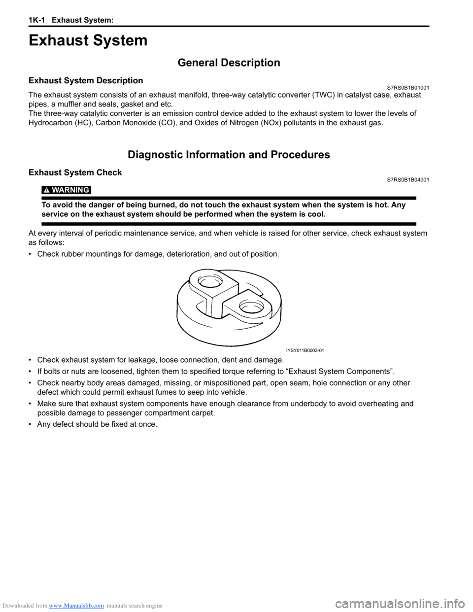
• Check rubber mountings for damage, deterioration, and out of position.
• Check exhaust system for leakage, loose connection, dent and damage.
• If bolts or nuts are loosened, tighten them to specified torque referring to “Exhaust System Components”.
• Check nearby body areas damaged, missing, or mispositio ned part, open seam, hole connection or any other
defect which could permit exhaust fumes to seep into vehicle.
• Make sure that exhaust system components have enough clearance from underbody to avoid overheating and
possible damage to passenger compartment carpet.
• Any defect should be fixed at once.
IYSY011B0003-01
Page 872 of 1496
Downloaded from www.Manualslib.com manuals search engine 6B-1 Steering Wheel and Column:
Steeri ng
Steering Wheel and Column
Precautions
Service Precautions of Steering Wheel and
Column
S7RS0B6200001
For service precautions, refer to “Precautions on Service
and Diagnosis of Air Bag System in Section 8B”.
Service and Diagnosis
For diagnosis and servicing, refer to “Precautions on
Service and Diagnosis of Air Bag System in Section 8B”.
Disabling Air Bag System
For disabling air bag system, refer to “Disabling Air Bag
System in Section 8B”. Enabling Air Bag System
For enabling air bag system, refer to “Enabling Air Bag
System in Section 8B”.
Handling and Storage
For handling and storage, refer to “Precautions on
Handling and Storage of Air Bag System Components in
Section 8B”.
Disposal
For disposal, refer to “Prec
autions on Disposal of Air
Bag and Seat Belt Pretensioner in Section 8B”.
General Description
Steering Wheel and Column ConstructionS7RS0B6201001
This double tube type steering column has the following three important features in addition to the steering function:
• The column is energy absorbing, desig ned to compress in a front-end collision.
• The ignition switch and lock are mounted conveniently on this column.
• With the column mounted lock, the ignition and steering op erations can be locked to inhibit theft of the vehicle.
To insure the energy absorbing action, it is important th at only the specified screws, bolts and nuts be used as
designated, and that they are tightened to the specified torque. When the column assembly is removed from the
vehicle, special care must be taken in handling it. Use of a steering wheel puller or a sharp blow on the end of the
steering shaft, leaning on the assembly, or dropping the a ssembly could shear the plastic shear pins which maintain
column length and position.
The driver air bag (inflator) module is one of the supplemental restraint (air bag) system components and is mounted
to the center of the steering wheel. During certain frontal crashes, the air bag system supplements the restraint of the
driver’s and passenger’s seat belts by deploying the air b ags. The air bag (inflator) module should be handled with
care to prevent accidental deployment. When servicing, be sure to observe “Precautions on Service and Diagnosis of
Air Bag System in Section 8B”.
Page 943 of 1496
Downloaded from www.Manualslib.com manuals search engine Heater and Ventilation: 7A-7
HVAC Control Unit Removal and InstallationS7RS0B7106009
Removal1) Disconnect negative (–) cable at battery.
2) Disable air bag system referring to “Disabling Air Bag System in Section 8B”.
3) Remove passenger air bag module from instrument panel referring to “Passenger Air Bag (Inflator)
Module Removal and Installation in Section 8B”.
4) Remove radio assembly from instrument panel referring to “Audio Unit Re moval and Installation in
Section 9C”.
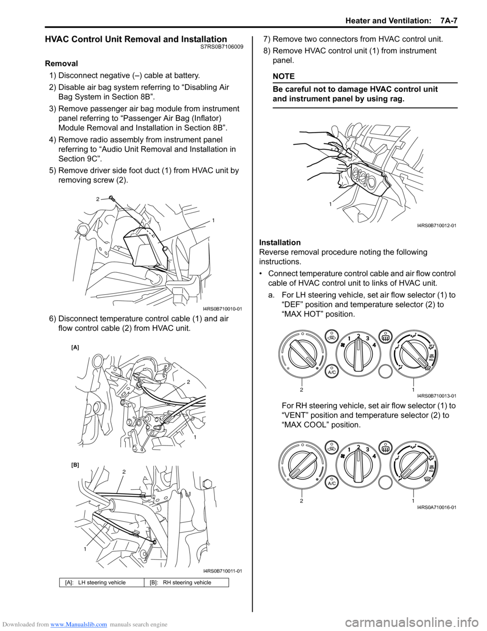
5) Remove driver side foot duct (1) from HVAC unit by removing screw (2).
6) Disconnect temperature control cable (1) and air flow control cable (2) from HVAC unit. 7) Remove two connectors from HVAC control unit.
8) Remove HVAC control unit (1) from instrument
panel.
NOTE
Be careful not to damage HVAC control unit
and instrument panel by using rag.
Installation
Reverse removal procedure noting the following
instructions.
• Connect temperature control cable and air flow control
cable of HVAC control unit to links of HVAC unit.
a. For LH steering vehicle, set air flow selector (1) to “DEF” position and temperature selector (2) to
“MAX HOT” position.
For RH steering vehicle, set air flow selector (1) to
“VENT” position and temperature selector (2) to
“MAX COOL” position.
[A]: LH steering vehicle [B]: RH steering vehicle
2
1
I4RS0B710010-01
2
1
1
2
[B] [A]
I4RS0B710011-01
1
I4RS0B710012-01
12I4RS0B710013-01
12I4RS0A710016-01
Page 946 of 1496
Downloaded from www.Manualslib.com manuals search engine 7A-10 Heater and Ventilation:
Air Intake Control Actuator InspectionS7RS0B7106013
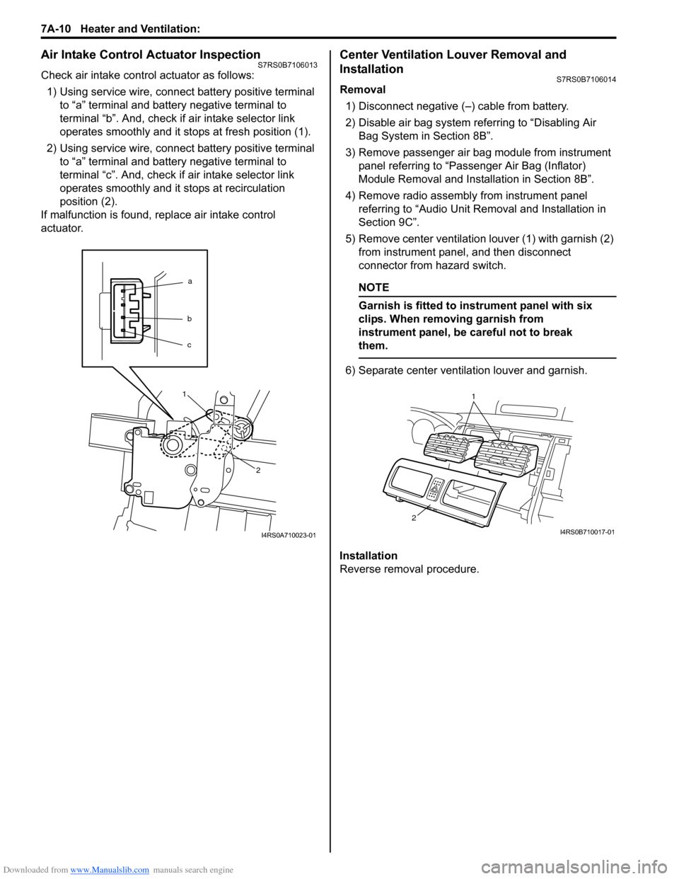
Check air intake control actuator as follows:1) Using service wire, connect battery positive terminal to “a” terminal and battery negative terminal to
terminal “b”. And, check if air intake selector link
operates smoothly and it st ops at fresh position (1).
2) Using service wire, connect battery positive terminal to “a” terminal and battery negative terminal to
terminal “c”. And, check if air intake selector link
operates smoothly and it stops at recirculation
position (2).
If malfunction is found, replace air intake control
actuator.
Center Ventilation Louver Removal and
Installation
S7RS0B7106014
Removal
1) Disconnect negative (–) cable from battery.
2) Disable air bag system referring to “Disabling Air Bag System in Section 8B”.
3) Remove passenger air bag module from instrument panel referring to “Passenger Air Bag (Inflator)
Module Removal and Installation in Section 8B”.
4) Remove radio assembly from instrument panel referring to “Audio Unit Re moval and Installation in
Section 9C”.
5) Remove center ventilation louver (1) with garnish (2) from instrument panel, and then disconnect
connector from hazard switch.
NOTE
Garnish is fitted to in strument panel with six
clips. When removing garnish from
instrument panel, be careful not to break
them.
6) Separate center ventilation louver and garnish.
Installation
Reverse removal procedure.
a
b
c
1
2
I4RS0A710023-01
1
2
I4RS0B710017-01
Page 947 of 1496
Downloaded from www.Manualslib.com manuals search engine Heater and Ventilation: 7A-11
Side Ventilation Louver Removal and
Installation
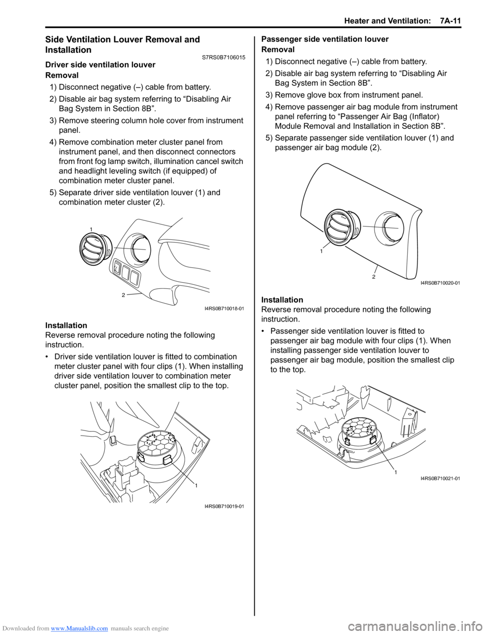
S7RS0B7106015
Driver side ventilation louver
Removal1) Disconnect negative (–) cable from battery.
2) Disable air bag system referring to “Disabling Air Bag System in Section 8B”.
3) Remove steering column hol e cover from instrument
panel.
4) Remove combination meter cluster panel from instrument panel, and then disconnect connectors
from front fog lamp switch, illumination cancel switch
and headlight leveling switch (if equipped) of
combination meter cluster panel.
5) Separate driver side ventilation louver (1) and combination meter cluster (2).
Installation
Reverse removal procedure noting the following
instruction.
• Driver side ventilation louver is fitted to combination meter cluster panel with four clips (1). When installing
driver side ventilation louv er to combination meter
cluster panel, position the smallest clip to the top. Passenger side ventilation louver
Removal
1) Disconnect negative (–) cable from battery.
2) Disable air bag system referring to “Disabling Air Bag System in Section 8B”.
3) Remove glove box from instrument panel.
4) Remove passenger air bag module from instrument panel referring to “Passenger Air Bag (Inflator)
Module Removal and Installation in Section 8B”.
5) Separate passenger side ventilation louver (1) and passenger air bag module (2).
Installation
Reverse removal procedure noting the following
instruction.
• Passenger side ventilation louver is fitted to passenger air bag module with four clips (1). When
installing passenger side ventilation louver to
passenger air bag module, position the smallest clip
to the top.
2
1
I4RS0B710018-01
1
I4RS0B710019-01
2
1
I4RS0B710020-01
1I4RS0B710021-01