timing marks SUZUKI SWIFT 2005 2.G Service Workshop Manual
[x] Cancel search | Manufacturer: SUZUKI, Model Year: 2005, Model line: SWIFT, Model: SUZUKI SWIFT 2005 2.GPages: 1496, PDF Size: 34.44 MB
Page 310 of 1496

Downloaded from www.Manualslib.com manuals search engine 1D-25 Engine Mechanical:
Timing Chain and Chain Tensioner Removal
and Installation
S7RS0B1406018
Removal
CAUTION!
After timing chain is removed, never turn
crankshaft and camshafts independently
more than its allowable turning range
described in “Installation”.
If turned, interferen ce may occur between
piston and valves and valves themselves,
and parts related to piston and valves may be
damaged.
1) Remove timing chain cover referring to “Timing Chain Cover Removal and Installation”.
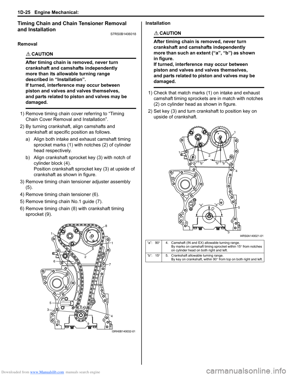
2) By turning crankshaft, align camshafts and crankshaft at specific position as follows.
a) Align both intake and exhaust camshaft timing sprocket marks (1) with notches (2) of cylinder
head respectively.
b) Align crankshaft sprocket key (3) with notch of cylinder block (4).
Position crankshaft sprocke t key (3) at upside of
crankshaft as shown in figure.
3) Remove timing chain tensioner adjuster assembly (5).
4) Remove timing chain tensioner (6).
5) Remove timing chain No.1 guide (7).
6) Remove timing chain (8) with crankshaft timing sprocket (9). Installation
CAUTION!
After timing chain is removed, never turn
crankshaft and camshafts independently
more than such an extent (“a”, “b”) as shown
in figure.
If turned, interferen
ce may occur between
piston and valves and valves themselves,
and parts related to piston and valves may be
damaged.
1) Check that match marks (1) on intake and exhaust camshaft timing sprockets are in match with notches
(2) on cylinder head as shown in figure.
2) Set key (3) and turn crankshaft to position key on upside of crankshaft.
3
4
1
1
2
5
67
8
9
I3RH0B140032-01
“a”: 90 °4. Camshaft (IN and EX) allowable turning range.
By marks on camshaft timing sprocket within 15 ° from notches
on cylinder head on both right and left.
“b”: 15 °5. Crankshaft allowable turning range.
By key on crankshaft, within 90 ° from top on both right and left.
“a”
“b”
“b”“b”
“b”
“a”
1
12
4
3
5
I4RS0A140021-01
Page 311 of 1496

Downloaded from www.Manualslib.com manuals search engine Engine Mechanical: 1D-26
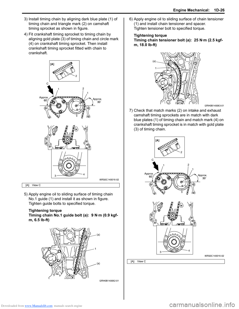
3) Install timing chain by aligning dark blue plate (1) of timing chain and triangle mark (2) on camshaft
timing sprocket as shown in figure.
4) Fit crankshaft timing sprocket to timing chain by aligning gold plate (3) of timing chain and circle mark
(4) on crankshaft timing sprocket. Then install
crankshaft timing sprocket fitted with chain to
crankshaft.
5) Apply engine oil to sliding surface of timing chain No.1 guide (1) and install it as shown in figure.
Tighten guide bolts to specified torque.
Tightening torque
Timing chain No.1 guide bolt (a): 9 N·m (0.9 kgf-
m, 6.5 lb-ft) 6) Apply engine oil to sliding surface of chain tensioner
(1) and install chain tensioner and spacer.
Tighten tensioner bolt to specified torque.
Tightening torque
Timing chain tensioner bolt (a): 25 N·m (2.5 kgf-
m, 18.0 lb-ft)
7) Check that match marks (2) on intake and exhaust camshaft timing sprockets are in match with dark
blue plates (1) of timing chain and match mark (4) on
crankshaft timing sprocket is in match with gold plate
(3) of timing chain.
[A]: View C
34
1
1
2
2
Approx. Approx.
C[A]
I6RS0C140016-02
I2RH0B140062-01
[A]: View C
I2RH0B140063-01
34
1
1
2
2
Approx. Approx.
C[A]
I6RS0C140016-02
Page 312 of 1496

Downloaded from www.Manualslib.com manuals search engine 1D-27 Engine Mechanical:
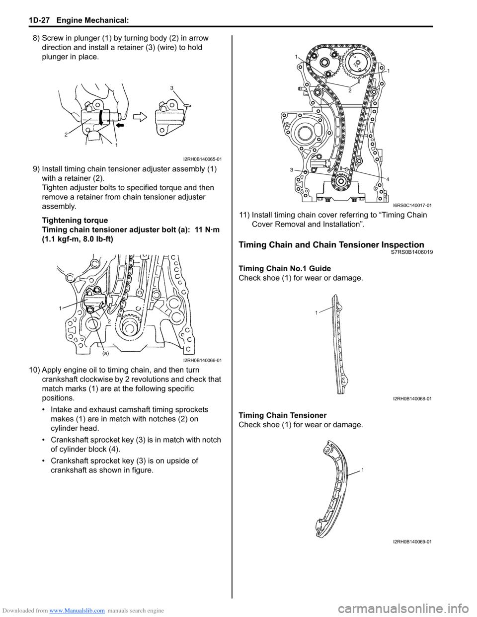
8) Screw in plunger (1) by turning body (2) in arrow direction and install a reta iner (3) (wire) to hold
plunger in place.
9) Install timing chain tensioner adjuster assembly (1) with a retainer (2).
Tighten adjuster bolts to specified torque and then
remove a retainer from chain tensioner adjuster
assembly.
Tightening torque
Timing chain tensioner adjuster bolt (a): 11 N·m
(1.1 kgf-m, 8.0 lb-ft)
10) Apply engine oil to timing chain, and then turn crankshaft clockwise by 2 revolutions and check that
match marks (1) are at the following specific
positions.
• Intake and exhaust camshaft timing sprockets makes (1) are in match with notches (2) on
cylinder head.
• Crankshaft sprocket key (3) is in match with notch of cylinder block (4).
• Crankshaft sprocket key (3) is on upside of crankshaft as shown in figure. 11) Install timing chain cover referring to “Timing Chain
Cover Removal and Installation”.
Timing Chain and Chain Tensioner InspectionS7RS0B1406019
Timing Chain No.1 Guide
Check shoe (1) for wear or damage.
Timing Chain Tensioner
Check shoe (1) for wear or damage.
I2RH0B140065-01
I2RH0B140066-01
1
1
2
3 4
I6RS0C140017-01
I2RH0B140068-01
I2RH0B140069-01
Page 315 of 1496

Downloaded from www.Manualslib.com manuals search engine Engine Mechanical: 1D-30
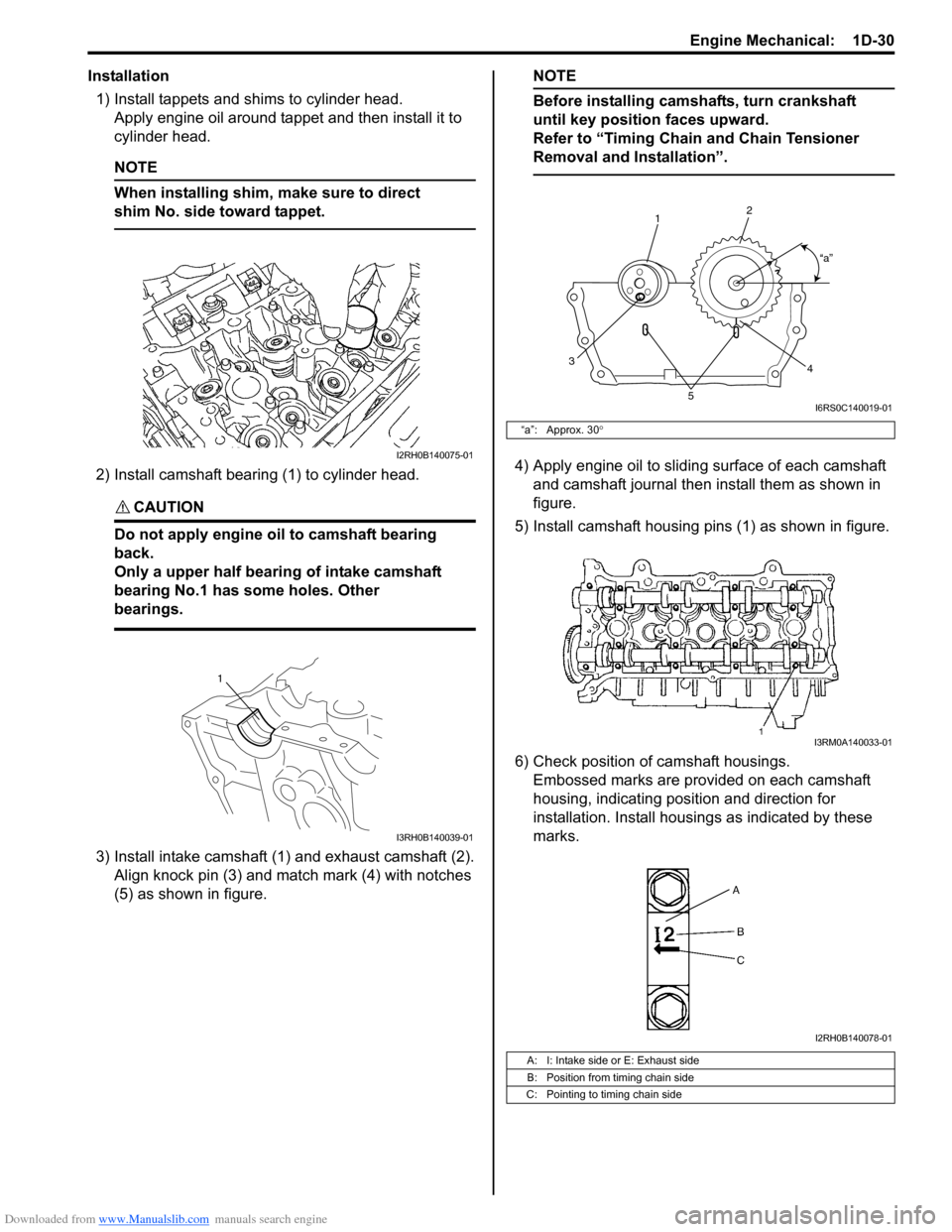
Installation1) Install tappets and shims to cylinder head. Apply engine oil around tappet and then install it to
cylinder head.
NOTE
When installing shim, make sure to direct
shim No. side toward tappet.
2) Install camshaft bearing (1) to cylinder head.
CAUTION!
Do not apply engine oil to camshaft bearing
back.
Only a upper half bearing of intake camshaft
bearing No.1 has some holes. Other
bearings.
3) Install intake camshaft (1) and exhaust camshaft (2). Align knock pin (3) and match mark (4) with notches
(5) as shown in figure.
NOTE
Before installing camshafts, turn crankshaft
until key position faces upward.
Refer to “Timing Chain and Chain Tensioner
Removal and Installation”.
4) Apply engine oil to sliding surface of each camshaft and camshaft journal then install them as shown in
figure.
5) Install camshaft housing pins (1) as shown in figure.
6) Check position of camshaft housings. Embossed marks are provided on each camshaft
housing, indicating position and direction for
installation. Install housings as indicated by these
marks.I2RH0B140075-01
1
I3RH0B140039-01
“a”: Approx. 30 °
A: I: Intake side or E: Exhaust side
B: Position from timing chain side
C: Pointing to timing chain side
1 2
3 4
5
“a”
I6RS0C140019-01
I3RM0A140033-01
I2RH0B140078-01