width SUZUKI SWIFT 2005 2.G Service Workshop Manual
[x] Cancel search | Manufacturer: SUZUKI, Model Year: 2005, Model line: SWIFT, Model: SUZUKI SWIFT 2005 2.GPages: 1496, PDF Size: 34.44 MB
Page 24 of 1496
Downloaded from www.Manualslib.com manuals search engine 0A-3 General Information:
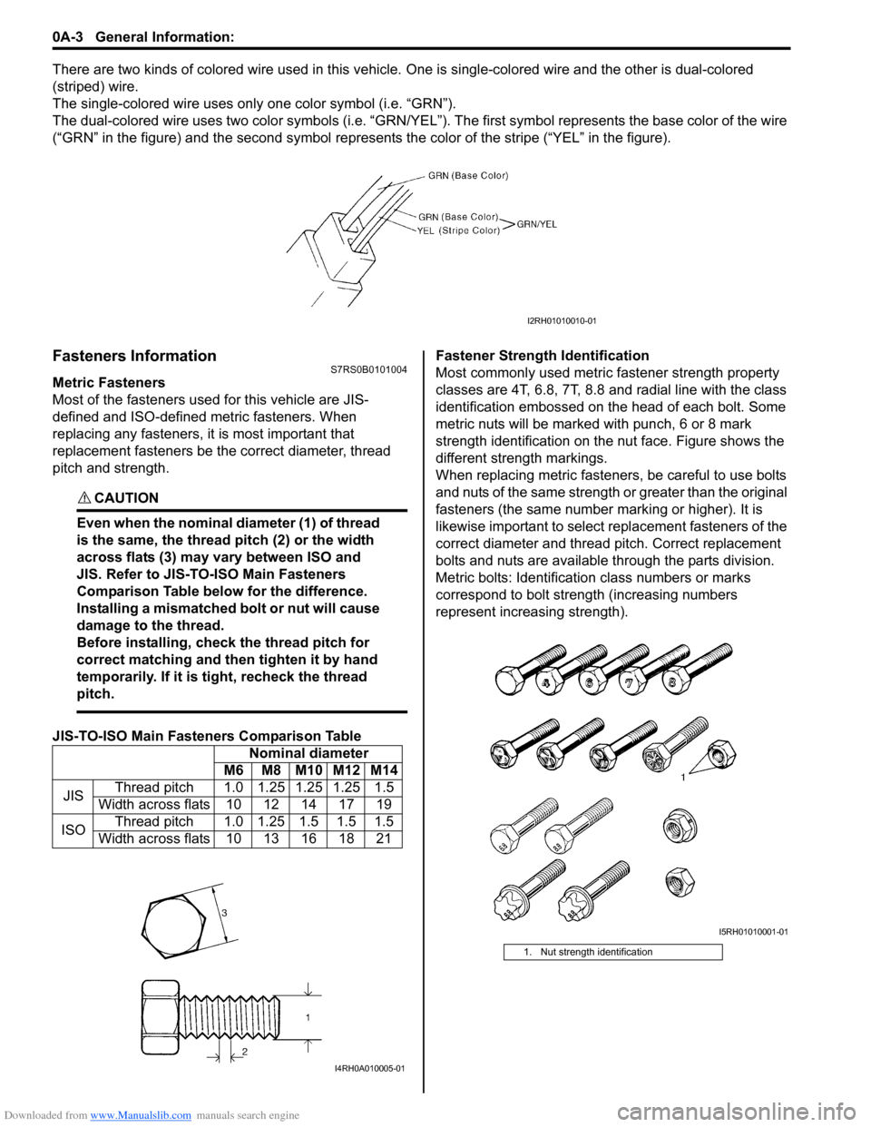
There are two kinds of colored wire used in this vehicle. One is single-colored wire and the other is dual-colored
(striped) wire.
The single-colored wire uses only one color symbol (i.e. “GRN”).
The dual-colored wire uses two color sy mbols (i.e. “GRN/YEL”). The first symbo l represents the base color of the wire
(“GRN” in the figure) and the second symbol represents the color of the stripe (“YEL” in the figure).
Fasteners InformationS7RS0B0101004
Metric Fasteners
Most of the fasteners used for this vehicle are JIS-
defined and ISO-defined metric fasteners. When
replacing any fasteners, it is most important that
replacement fasteners be the correct diameter, thread
pitch and strength.
CAUTION!
Even when the nominal diameter (1) of thread
is the same, the thread pitch (2) or the width
across flats (3) may vary between ISO and
JIS. Refer to JIS-TO-ISO Main Fasteners
Comparison Table below for the difference.
Installing a mismatched bolt or nut will cause
damage to the thread.
Before installing, check the thread pitch for
correct matching and then tighten it by hand
temporarily. If it is tight, recheck the thread
pitch.
JIS-TO-ISO Main Fasteners Comparison Table Fastener Strength Identification
Most commonly used metric fastener strength property
classes are 4T, 6.8, 7T, 8.8 and radial line with the class
identification embossed on the head of each bolt. Some
metric nuts will be marked with punch, 6 or 8 mark
strength identification on the nut face. Figure shows the
different strength markings.
When replacing metric fasteners, be careful to use bolts
and nuts of the same strength or greater than the original
fasteners (the same number marking or higher). It is
likewise important to select replacement fasteners of the
correct diameter and thread
pitch. Correct replacement
bolts and nuts are available through the parts division.
Metric bolts: Identification class numbers or marks
correspond to bolt strength (increasing numbers
represent increasing strength).
I2RH01010010-01
Nominal diameter
M6 M8 M10 M12 M14
JIS Thread pitch 1.0 1.25 1.25 1.25 1.5
Width across flats 10 12 14 17 19
ISO Thread pitch 1.0 1.25 1.5 1.5 1.5
Width across flats 10 13 16 18 21
I4RH0A010005-01
1. Nut strength identification
I5RH01010001-01
Page 83 of 1496
Downloaded from www.Manualslib.com manuals search engine Engine General Information and Diagnosis: 1A-33
Scan Tool DataS7RS0B1104007
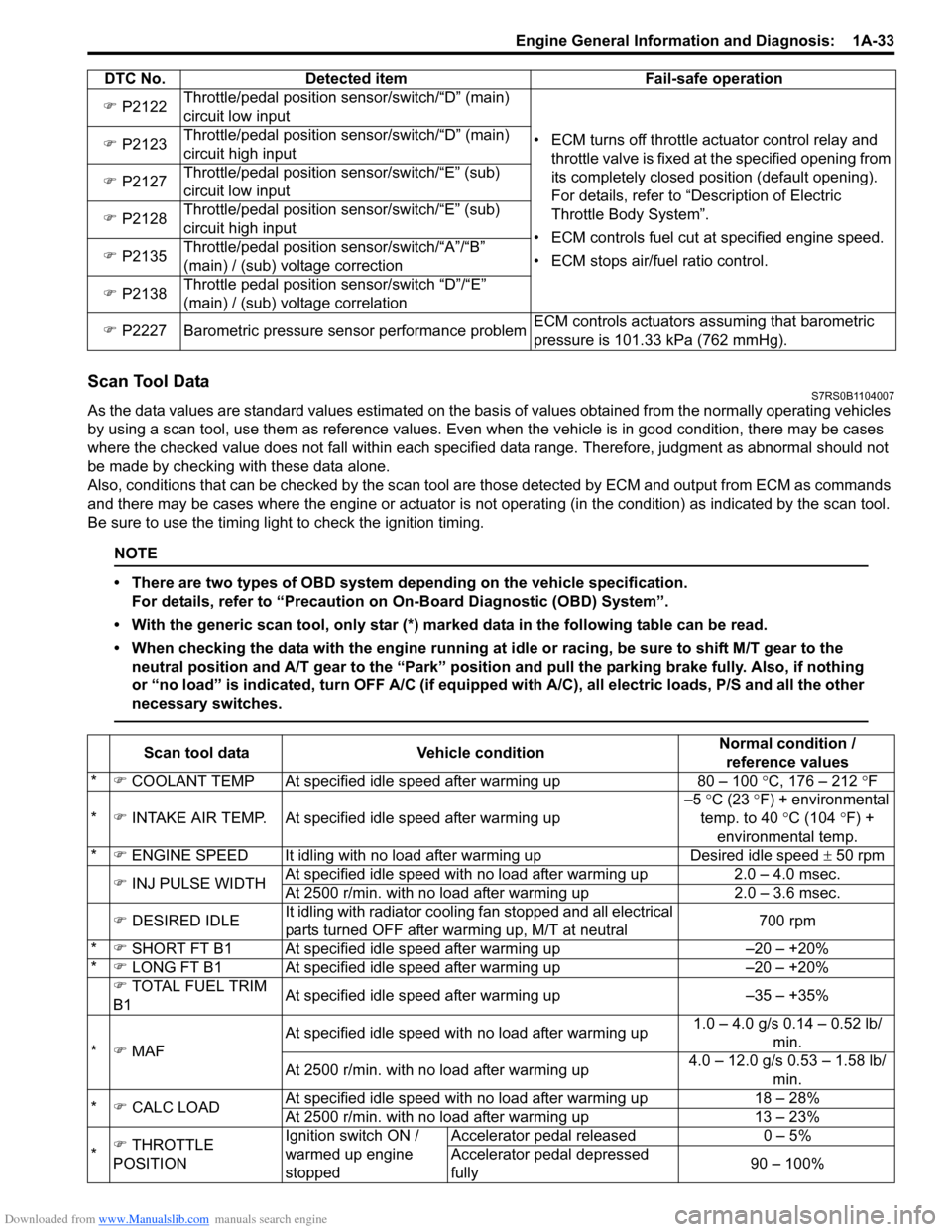
As the data values are standard values estimated on the basis of values obtained from the normally operating vehicles
by using a scan tool, use them as re ference values. Even when the vehicle is in good condition, there may be cases
where the checked value does not fall within each specified data range. Therefore, judgment as abnormal should not
be made by checking with these data alone.
Also, conditions that can be checked by the scan tool are those detected by ECM and output from ECM as commands
and there may be cases where the engine or actuator is not operating (in the condition) as indicated by the scan tool.
Be sure to use the timing light to check the ignition timing.
NOTE
• There are two types of OBD system depending on the vehicle specification.
For details, refer to “Precaution on On-Board Diagnostic (OBD) System”.
• With the generic scan tool, only star (*) marked data in the following table can be read.
• When checking the data with the engine running at idle or racing, be sure to shift M/T gear to the neutral position and A/T gear to the “Park” position and pull the parking brake fully. Also, if nothing
or “no load” is indicated, turn O FF A/C (if equipped with A/C), all electric loads, P/S and all the other
necessary switches.
�) P2122 Throttle/pedal position sensor/switch/“D” (main)
circuit low input
• ECM turns off throttle actuator control relay and throttle valve is fixed at the specified opening from
its completely closed position (default opening).
For details, refer to “Description of Electric
Throttle Body System”.
• ECM controls fuel cut at specified engine speed.
• ECM stops air/fuel ratio control.
�)
P2123 Throttle/pedal position sensor/switch/“D” (main)
circuit high input
�) P2127 Throttle/pedal position sensor/switch/“E” (sub)
circuit low input
�) P2128 Throttle/pedal position sensor/switch/“E” (sub)
circuit high input
�) P2135 Throttle/pedal position sensor/switch/“A”/“B”
(main) / (sub) voltage correction
�) P2138 Throttle pedal position sensor/switch “D”/“E”
(main) / (sub) voltage correlation
�) P2227 Barometric pressure sensor performance problem ECM controls actuators assuming that barometric
pressure is 101.33 kPa (762 mmHg).
DTC No. Detected item Fail-safe operation
Scan tool data
Vehicle condition Normal condition /
reference values
* �) COOLANT TEMP At specified idle speed after warming up 80 – 100 °C, 176 – 212 °F
* �) INTAKE AIR TEMP. At specifie d idle speed after warming up –5
°C (23 °F) + environmental
temp. to 40 °C (104 °F) +
environmental temp.
* �) ENGINE SPEED It idling with no load after warming upDesired idle speed ± 50 rpm
�) INJ PULSE WIDTH At specified idle speed with no load after warming up
2.0 – 4.0 msec.
At 2500 r/min. with no load after warming up 2.0 – 3.6 msec.
�) DESIRED IDLE It idling with radiator cooling fan stopped and all electrical
parts turned OFF after warming up, M/T at neutral 700 rpm
* �) SHORT FT B1 At specified idle speed after warming up –20 – +20%
* �) LONG FT B1 At specified idle speed after warming up –20 – +20%
�) TOTAL FUEL TRIM
B1 At specified idle speed after warming up
–35 – +35%
* �) MAF At specified idle speed wit
h no load after warming up 1.0 – 4.0 g/s 0.14 – 0.52 lb/
min.
At 2500 r/min. with no load after warming up 4.0 – 12.0 g/s 0.53 – 1.58 lb/
min.
* �) CALC LOAD At specified idle speed with no load after warming up
18 – 28%
At 2500 r/min. with no load after warming up 13 – 23%
* �)
THROTTLE
POSITION Ignition switch ON /
warmed up engine
stoppedAccelerator pedal released
0 – 5%
Accelerator pedal depressed
fully 90 – 100%
Page 85 of 1496
Downloaded from www.Manualslib.com manuals search engine Engine General Information and Diagnosis: 1A-35
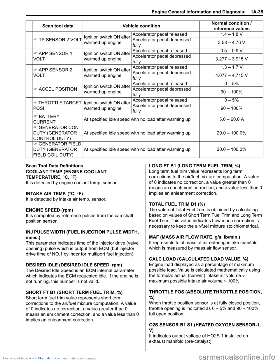
Scan Tool Data Definitions
COOLANT TEMP (ENGINE COOLANT
TEMPERATURE, °C, °F)
It is detected by engine coolant temp. sensor.
INTAKE AIR TEMP. ( °C, °F)
It is detected by intake air temp. sensor.
ENGINE SPEED (rpm)
It is computed by reference pulses from the camshaft
position sensor.
INJ PULSE WIDTH (FUEL INJECTION PULSE WIDTH,
msec.)
This parameter indicates time of the injector drive (valve
opening) pulse which is output from ECM (but injector
drive time of NO.1 cylinder fo r multiport fuel injection).
DESIRED IDLE (DESIRED IDLE SPEED, rpm)
The Desired Idle Speed is an ECM internal parameter
which indicates the ECM requested idle. If the engine is
not running, this number is not valid.
SHORT FT B1 (SHORT TERM FUEL TRIM, %)
Short term fuel trim valu e represents short term
corrections to the air/fuel mixture computation. A value
of 0 indicates no correction, a value greater than 0
means an enrichment correction, and a value less than 0
implies an enleanment correction. LONG FT B1 (LONG TERM FUEL TRIM, %)
Long term fuel trim value represents long term
corrections to the air/fuel mixture computation. A value
of 0 indicates no correction, a value greater than 0
means an enrichment correction, and a value less than 0
implies an enleanment correction.
TOTAL FUEL TRIM B1 (%)
The value of Total Fuel Trim is obtained by calculating
based on values of Short Term Fuel Trim and Long Term
Fuel Trim. This value indica
tes how much correction is
necessary to keep the air/fuel mixture stoichiometrical.
MAF (MASS AIR FLOW RATE, g/s, lb/min.)
It represents total mass of air entering intake manifold
which is measured by mass air flow sensor.
CALC LOAD (CALCULATED LOAD VALUE, %)
Engine load displayed as a percentage of maximum
possible load. Value is calculated mathematically using
the formula: actual (current) intake air volume ÷
maximum possible intake air volume × 100%
THROTTLE POS (ABSOLUTE THROTTLE POSITION,
%)
When throttle position sensor is at fully closed position,
throttle opening is indicated as 0 – 5% and 90 – 100%
full open position.
O2S SENSOR B1 S1 (HEA TED OXYGEN SENSOR-1,
V)
It indicates output voltage of HO2S-1 installed on
exhaust manifold (pre-catalyst).
�)
TP SENSOR 2 VOLT Ignition switch ON after
warmed up engine Accelerator pedal released
1.4 – 1.8 V
Accelerator pedal depressed
fully 3.58 – 4.76 V
�) APP SENSOR 1
VOLT Ignition switch ON after
warmed up engineAccelerator pedal released
0.5 – 0.9 V
Accelerator pedal depressed
fully 3.277 – 3.915 V
�) APP SENSOR 2
VOLT Ignition switch ON after
warmed up engineAccelerator pedal released
1.3 – 1.7 V
Accelerator pedal depressed
fully 4.077 – 4.715 V
�) ACCEL POSITION Ignition switch ON after
warmed up engine Accelerator pedal released
0 – 5%
Accelerator pedal depressed
fully 90 – 100%
�) THROTTLE TARGET
POSI Ignition switch ON after
warmed up engineAccelerator pedal released
0 – 5%
Accelerator pedal depressed
fully 90 – 100%
�) BATTERY
CURRENT At specified idle speed with no load after warming up
5.0 – 60.0 A
�) GENERATOR CONT
DUTY (GENERATOR
CONTROL DUTY) At specified idle speed with no load after warming up
20.0 – 100.0%
�) GENERATOR FIELD
DUTY (GENERATOR
FIELD COIL DUTY) At spe
cified idle speed with no load after warming up
20.0 – 100.0%
Scan tool data
Vehicle condition Normal condition /
reference values
Page 234 of 1496
Downloaded from www.Manualslib.com manuals search engine 1A-184 Engine General Information and Diagnosis:
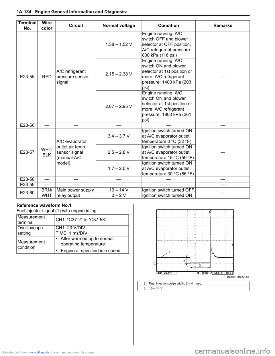
Reference waveform No.1
Fuel injector signal (1) with engine idling
E23-55 RED
A/C refrigerant
pressure sensor
signal 1.38 – 1.52 V
Engine running, A/C
switch OFF and blower
selector at OFF position,
A/C refrigerant pressure:
800 kPa (116 psi)
—
2.15 – 2.38 V Engine running, A/C
switch ON and blower
selector at 1st position or
more, A/C refrigerant
pressure: 1400 kPa (203
psi)
2.67 – 2.95 V Engine running, A/C
switch ON and blower
selector at 1st position or
more, A/C refrigerant
pressure: 1800 kPa (261
psi)
E23-56 — — — — —
E23-57 WHT/
BLK A/C evaporator
outlet air temp.
sensor signal
(manual A/C
model) 3.4 – 3.7 V
Ignition switch turned ON
at A/C evaporator outlet
temperature 0
°C (32 °F).
—
2.5 – 2.8 V Ignition switch turned ON
at A/C evaporator outlet
temperature 15
°C (59 °F).
1.7 – 2.0 V Ignition switch turned ON
at A/C evaporator outlet
temperature 30
°C (86 °F).
E23-58 — — — — —
E23-59 — — — — —
E23-60 BRN/
WHT Main power supply
relay output 10 – 14 V Ignition switch turned OFF.
—
0 – 2 V Ignition switch turned ON.
Terminal
No. Wire
color Circuit Normal voltage Condition Remarks
Measurement
terminal CH1: “C37-2” to “C37-58”
Oscilloscope
setting CH1: 20 V/DIV
TIME: 1 ms/DIV
Measurement
condition • After warmed up to normal
operating temperature
• Engine at specified idle speed
2. Fuel injection pulse width: 2 – 4 msec.
3. 10 – 14 V
I4RS0B110050-01
Page 236 of 1496
Downloaded from www.Manualslib.com manuals search engine 1A-186 Engine General Information and Diagnosis:
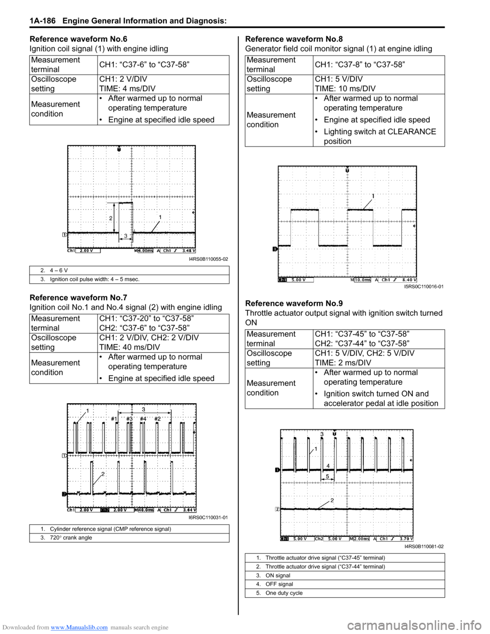
Reference waveform No.6
Ignition coil signal (1) with engine idling
Reference waveform No.7
Ignition coil No.1 and No.4 signal (2) with engine idlingReference waveform No.8
Generator field coil monitor signal (1) at engine idling
Reference waveform No.9
Throttle actuator output signal with ignition switch turned
ON
Measurement
terminal
CH1: “C37-6” to “C37-58”
Oscilloscope
setting CH1: 2 V/DIV
TIME: 4 ms/DIV
Measurement
condition • After warmed up to normal
operating temperature
• Engine at specified idle speed
2. 4 – 6 V
3. Ignition coil pulse width: 4 – 5 msec.
Measurement
terminal CH1: “C37-20” to “C37-58”
CH2: “C37-6” to “C37-58”
Oscilloscope
setting CH1: 2 V/DIV, CH2: 2 V/DIV
TIME: 40 ms/DIV
Measurement
condition • After warmed up to normal
operating temperature
• Engine at specified idle speed
1. Cylinder reference signal (CMP reference signal)
3. 720 ° crank angle
I4RS0B110055-02
I6RS0C110031-01
Measurement
terminal CH1: “C37-8” to “C37-58”
Oscilloscope
setting CH1: 5 V/DIV
TIME: 10 ms/DIV
Measurement
condition • After warmed up to normal
operating temperature
• Engine at specified idle speed
• Lighting switch at CLEARANCE position
Measurement
terminal CH1: “C37-45” to “C37-58”
CH2: “C37-44” to “C37-58”
Oscilloscope
setting CH1: 5 V/DIV, CH2: 5 V/DIV
TIME: 2 ms/DIV
Measurement
condition • After warmed up to normal
operating temperature
• Ignition switch turned ON and accelerator pedal at idle position
1. Throttle actuator drive signal (“C37-45” terminal)
2. Throttle actuator drive signal (“C37-44” terminal)
3. ON signal
4. OFF signal
5. One duty cycle
I5RS0C110016-01
I4RS0B110081-02
Page 307 of 1496
Downloaded from www.Manualslib.com manuals search engine Engine Mechanical: 1D-22
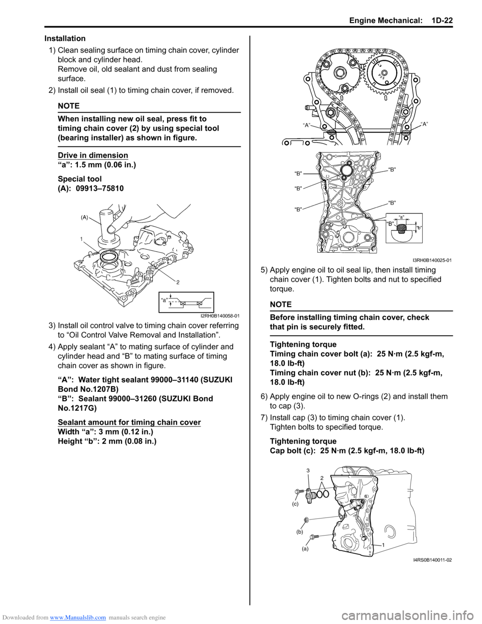
Installation1) Clean sealing surface on timing chain cover, cylinder block and cylinder head.
Remove oil, old sealant and dust from sealing
surface.
2) Install oil seal (1) to timi ng chain cover, if removed.
NOTE
When installing new oil seal, press fit to
timing chain cover (2) by using special tool
(bearing installer) as shown in figure.
Drive in dimension
“a”: 1.5 mm (0.06 in.)
Special tool
(A): 09913–75810
3) Install oil control valve to timing chain cover referring to “Oil Control Valve Removal and Installation”.
4) Apply sealant “A” to mating surface of cylinder and cylinder head and “B” to mating surface of timing
chain cover as shown in figure.
“A”: Water tight sealant 99000–31140 (SUZUKI
Bond No.1207B)
“B”: Sealant 99000–31260 (SUZUKI Bond
No.1217G)
Sealant amount for timing chain cover
Width “a”: 3 mm (0.12 in.)
Height “b”: 2 mm (0.08 in.) 5) Apply engine oil to oil seal lip, then install timing
chain cover (1). Tighten bolts and nut to specified
torque.
NOTE
Before installing timing chain cover, check
that pin is securely fitted.
Tightening torque
Timing chain cover bolt (a): 25 N·m (2.5 kgf-m,
18.0 lb-ft)
Timing chain cover nut (b): 25 N·m (2.5 kgf-m,
18.0 lb-ft)
6) Apply engine oil to new O-rings (2) and install them to cap (3).
7) Install cap (3) to ti ming chain cover (1).
Tighten bolts to specified torque.
Tightening torque
Cap bolt (c): 25 N·m (2.5 kgf-m, 18.0 lb-ft)
I2RH0B140058-01
I3RH0B140025-01
(a)
(b)
(c)
1
2
3
I4RS0B140011-02
Page 317 of 1496
Downloaded from www.Manualslib.com manuals search engine Engine Mechanical: 1D-32
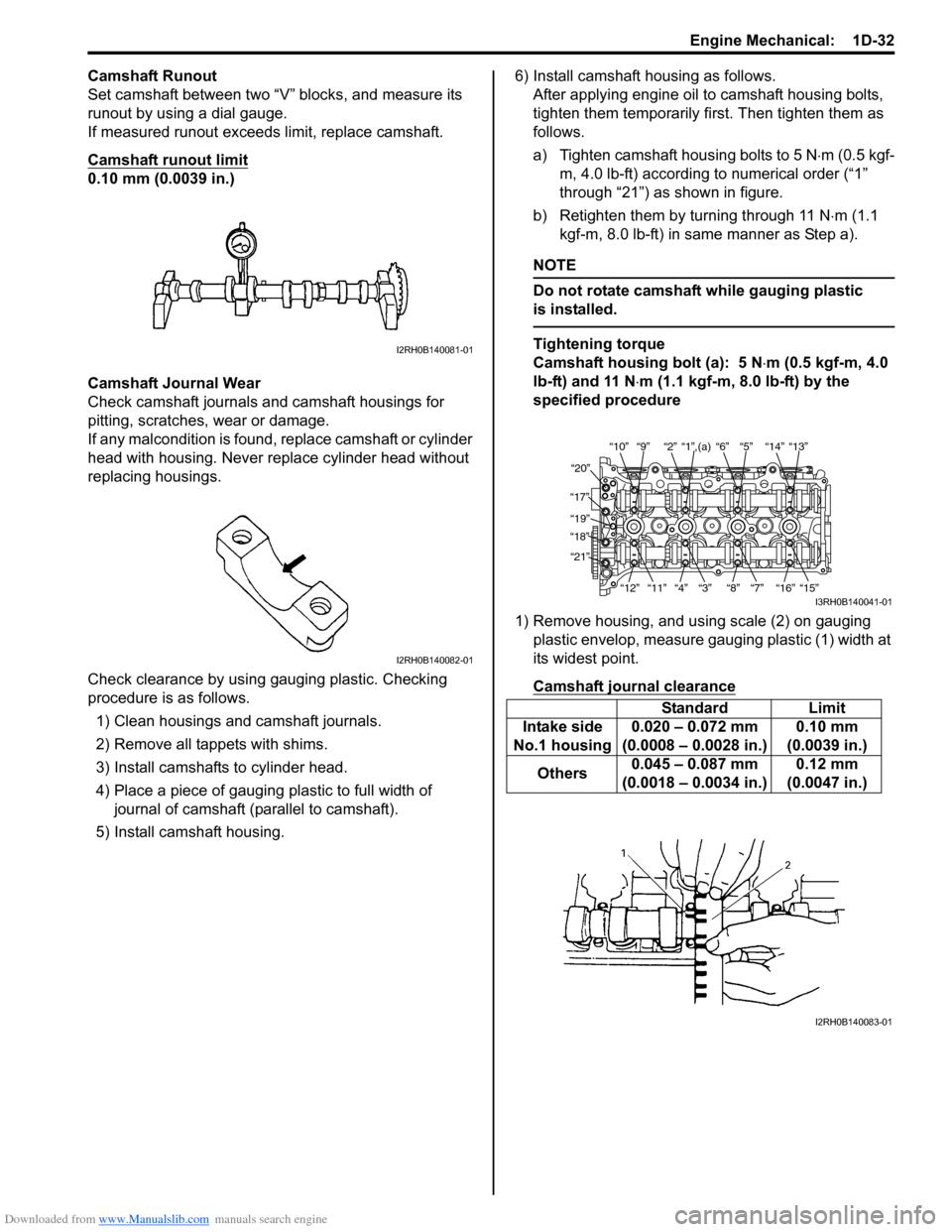
Camshaft Runout
Set camshaft between two “V” blocks, and measure its
runout by using a dial gauge.
If measured runout exceeds limit, replace camshaft.
Camshaft runout limit
0.10 mm (0.0039 in.)
Camshaft Journal Wear
Check camshaft journals and camshaft housings for
pitting, scratches, wear or damage.
If any malcondition is found, replace camshaft or cylinder
head with housing. Never re place cylinder head without
replacing housings.
Check clearance by using ga uging plastic. Checking
procedure is as follows.
1) Clean housings and camshaft journals.
2) Remove all tappets with shims.
3) Install camshafts to cylinder head.
4) Place a piece of gauging plastic to full width of
journal of camshaft (parallel to camshaft).
5) Install camshaft housing. 6) Install camshaft housing as follows.
After applying engine oil to camshaft housing bolts,
tighten them temporarily first. Then tighten them as
follows.
a) Tighten camshaft housing bolts to 5 N ⋅m (0.5 kgf-
m, 4.0 lb-ft) according to numerical order (“1”
through “21”) as shown in figure.
b) Retighten them by turning through 11 N ⋅m (1.1
kgf-m, 8.0 lb-ft) in same manner as Step a).
NOTE
Do not rotate camshaft while gauging plastic
is installed.
Tightening torque
Camshaft housing bolt (a): 5 N ⋅m (0.5 kgf-m, 4.0
lb-ft) and 11 N ⋅m (1.1 kgf-m, 8.0 lb-ft) by the
specified procedure
1) Remove housing, and using scale (2) on gauging plastic envelop, measure gauging plastic (1) width at
its widest point.
Camshaft journal clearanceI2RH0B140081-01
I2RH0B140082-01
Standard Limit
Intake side
No.1 housing 0.020 – 0.072 mm
(0.0008 – 0.0028 in.) 0.10 mm
(0.0039 in.)
Others 0.045 – 0.087 mm
(0.0018 – 0.0034 in.) 0.12 mm
(0.0047 in.)
“10”“9” “2” “1”,(a) “6” “5” “14” “13”
“20”
“17” “19”
“18”
“21”
“12”“11”
“4” “3” “8” “7” “16” “15”
I3RH0B140041-01
I2RH0B140083-01
Page 326 of 1496
Downloaded from www.Manualslib.com manuals search engine 1D-41 Engine Mechanical:
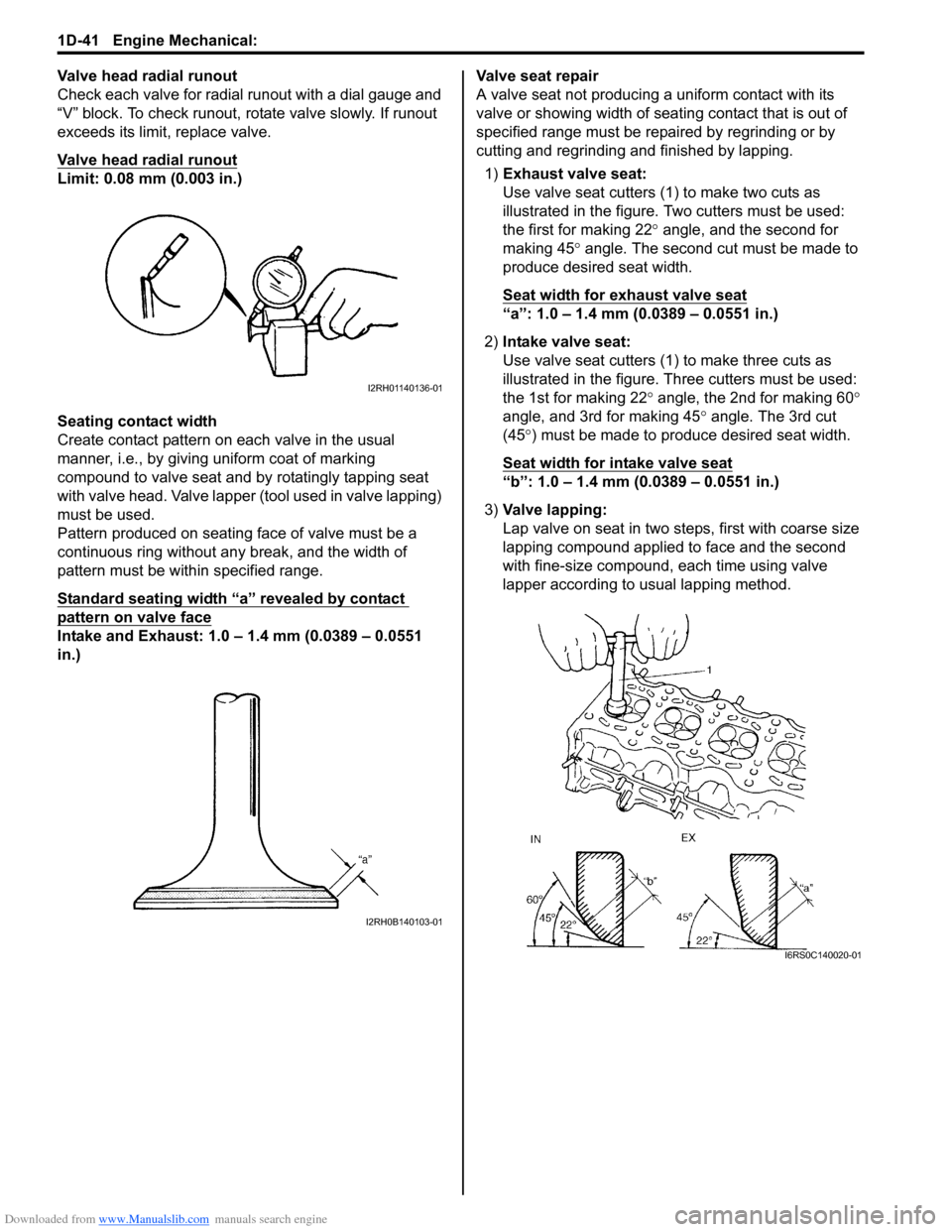
Valve head radial runout
Check each valve for radial runout with a dial gauge and
“V” block. To check runout, rotate valve slowly. If runout
exceeds its limit, replace valve.
Valve head radial runout
Limit: 0.08 mm (0.003 in.)
Seating contact width
Create contact pattern on each valve in the usual
manner, i.e., by giving uniform coat of marking
compound to valve seat and by rotatingly tapping seat
with valve head. Valve lapper (tool used in valve lapping)
must be used.
Pattern produced on seating face of valve must be a
continuous ring without any break, and the width of
pattern must be within specified range.
Standard seating width “a” revealed by contact
pattern on valve face
Intake and Exhaust: 1.0 – 1.4 mm (0.0389 – 0.0551
in.)Valve seat repair
A valve seat not producing
a uniform contact with its
valve or showing width of seating contact that is out of
specified range must be repaired by regrinding or by
cutting and regrinding and finished by lapping.
1) Exhaust valve seat:
Use valve seat cutters (1 ) to make two cuts as
illustrated in the figure. Two cutters must be used:
the first for making 22 ° angle, and the second for
making 45 ° angle. The second cut must be made to
produce desired seat width.
Seat width for exhaust valve seat
“a”: 1.0 – 1.4 mm (0.0389 – 0.0551 in.)
2) Intake valve seat:
Use valve seat cutters (1) to make three cuts as
illustrated in the figure. Th ree cutters must be used:
the 1st for making 22 ° angle, the 2nd for making 60 °
angle, and 3rd for making 45 ° angle. The 3rd cut
(45 °) must be made to produce desired seat width.
Seat width for intake valve seat
“b”: 1.0 – 1.4 mm (0.0389 – 0.0551 in.)
3) Valve lapping:
Lap valve on seat in two steps, first with coarse size
lapping compound applied to face and the second
with fine-size compound, each time using valve
lapper according to usual lapping method.
I2RH01140136-01
I2RH0B140103-01
I6RS0C140020-01
Page 336 of 1496
Downloaded from www.Manualslib.com manuals search engine 1D-51 Engine Mechanical:
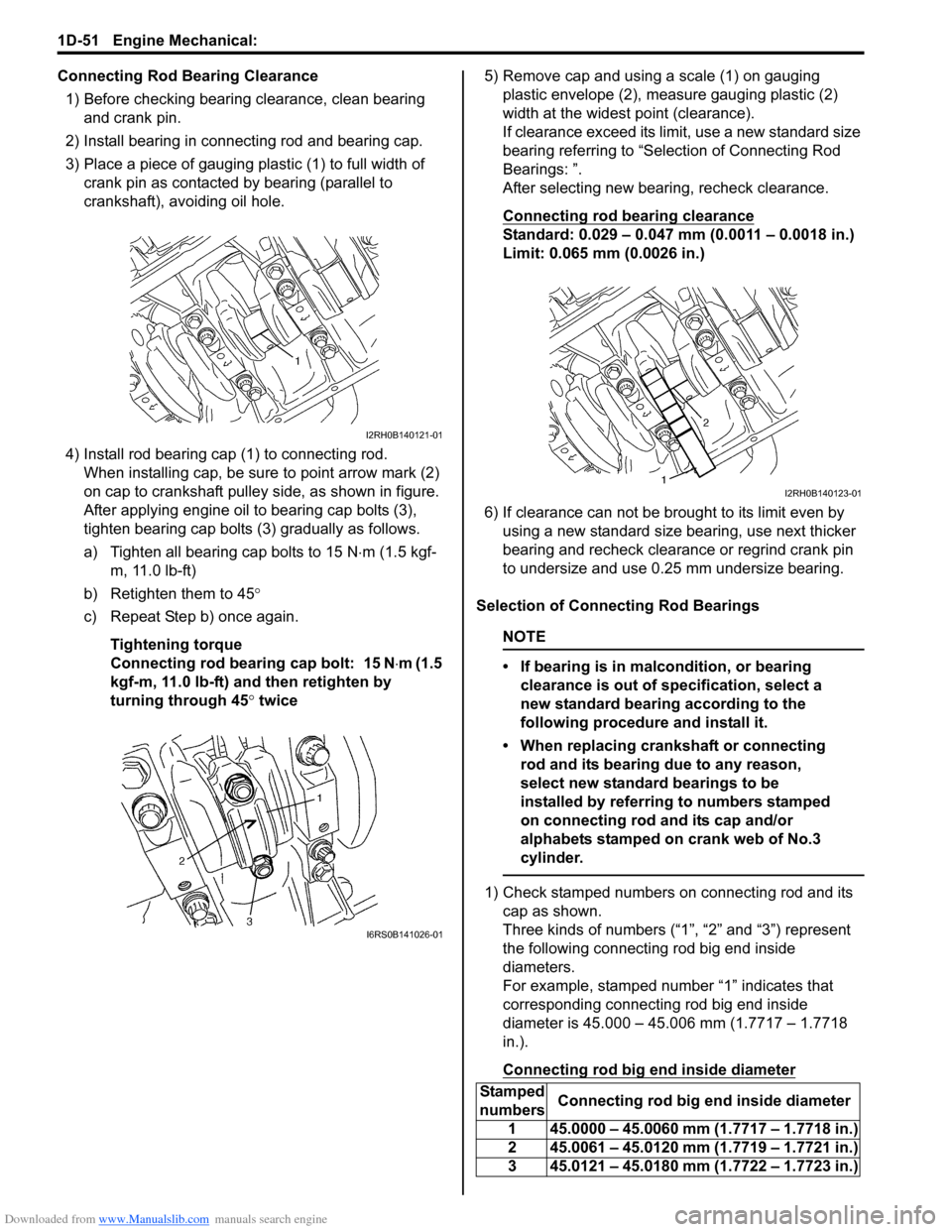
Connecting Rod Bearing Clearance1) Before checking bearing clearance, clean bearing and crank pin.
2) Install bearing in connecting rod and bearing cap.
3) Place a piece of gauging plastic (1) to full width of crank pin as contacted by bearing (parallel to
crankshaft), avoiding oil hole.
4) Install rod bearing cap (1) to connecting rod. When installing cap, be sure to point arrow mark (2)
on cap to crankshaft pulley side, as shown in figure.
After applying engine oil to bearing cap bolts (3),
tighten bearing cap bolts (3) gradually as follows.
a) Tighten all bearing cap bolts to 15 N ⋅m (1.5 kgf-
m, 11.0 lb-ft)
b) Retighten them to 45°
c) Repeat Step b) once again.
Tightening torque
Connecting rod bearing cap bolt: 15 N ⋅m (1.5
kgf-m, 11.0 lb-ft) and then retighten by
turning through 45 ° twice 5) Remove cap and using a scale (1) on gauging
plastic envelope (2), measure gauging plastic (2)
width at the widest point (clearance).
If clearance exceed its limit, use a new standard size
bearing referring to “Selection of Connecting Rod
Bearings: ”.
After selecting new bearing, recheck clearance.
Connecting rod bearing clearance
Standard: 0.029 – 0.047 mm (0.0011 – 0.0018 in.)
Limit: 0.065 mm (0.0026 in.)
6) If clearance can not be brought to its limit even by using a new standard size bearing, use next thicker
bearing and recheck clearance or regrind crank pin
to undersize and use 0.25 mm undersize bearing.
Selection of Connecting Rod Bearings
NOTE
• If bearing is in malcondition, or bearing clearance is out of specification, select a
new standard bearing according to the
following procedure and install it.
• When replacing crankshaft or connecting rod and its bearing due to any reason,
select new standard bearings to be
installed by referring to numbers stamped
on connecting rod and its cap and/or
alphabets stamped on crank web of No.3
cylinder.
1) Check stamped numbers on connecting rod and its cap as shown.
Three kinds of numbers (“1”, “2” and “3”) represent
the following connecting rod big end inside
diameters.
For example, stamped number “1” indicates that
corresponding connecting rod big end inside
diameter is 45.000 – 45.006 mm (1.7717 – 1.7718
in.).
Connecting rod big end inside diameter
I2RH0B140121-01
I6RS0B141026-01
Stamped
numbers Connecting rod big end inside diameter
1 45.0000 – 45.0060 mm (1.7717 – 1.7718 in.)
2 45.0061 – 45.0120 mm (1.7719 – 1.7721 in.)
3 45.0121 – 45.0180 mm (1.7722 – 1.7723 in.)
I2RH0B140123-01
Page 341 of 1496
Downloaded from www.Manualslib.com manuals search engine Engine Mechanical: 1D-56
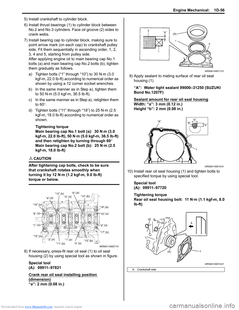
5) Install crankshaft to cylinder block.
6) Install thrust bearings (1) to cylinder block between No.2 and No.3 cylinders. Face oil groove (2) sides to
crank webs.
7) Install bearing cap to cylinder block, making sure to point arrow mark (on each cap) to crankshaft pulley
side. Fit them sequentially in ascending order, 1, 2,
3, 4 and 5, starting from pulley side.
After applying engine oil to main bearing cap No.1
bolts (a) and main bearing cap No.2 bolts (b), tighten
them gradually as follows.
a) Tighten bolts (“1” through “10”) to 30 N ⋅m (3.0
kgf-m, 22.0 lb-ft) according to numerical order as
shown by using a 12 corner socket wrenches.
b) In the same manner as in Step a), tighten them to 50 N ⋅m (5.0 kgf-m, 36.5 lb-ft).
c) In the same manner as in Step a), retighten them to 60 °.
d) Tighten bolts (“11” through “18”) to 25 N ⋅m (2.5
kgf-m, 18.0 lb-ft) according to numerical order as
shown.
Tightening torque
Main bearing cap No.1 bolt (a): 30 N ⋅m (3.0
kgf-m, 22.0 lb-ft), 50 N ⋅m (5.0 kgf-m, 36.5 lb-ft)
and then retighten by turning through 60 °
Main bearing cap No.2 bolt (b): 25 N·m (2.5
kgf-m, 18.0 lb-ft)
CAUTION!
After tightening cap bolts, check to be sure
that crankshaft rotates smoothly when
turning it by 12 N ⋅m (1.2 kgf-m, 9.0 lb-ft)
torque or below.
8) If necessary, press-fit rear oil seal (1) to oil seal housing (2) by using special tool as shown in figure.
Special tool
(A): 09911–97821
Crank rear oil seal installing position
(dimension)
“a”: 2 mm (0.08 in.) 9) Apply sealant to mating surface of rear oil seal
housing (1).
“A”: Water tight sealant 99000–31250 (SUZUKI
Bond No.1207F)
Sealant amount for rear oil seal housing
Width: “a”: 3 mm (0.12 in.)
Height “b”: 2 mm (0.08 in.)
10) Install rear oil seal housing (1) and tighten bolts to specified torque by using special tool.
Special tool
(A): 09911–97720
Tightening torque
Rear oil seal housing bolt: 11 N·m (1.1 kgf-m, 8.0
lb-ft)
I6RS0C140027-01
A: Crankshaft side
I4RS0A140017-01
I4RS0A140018-01
I4RS0A140019-01