Seat belt SUZUKI SWIFT 2006 2.G Service Workshop Manual
[x] Cancel search | Manufacturer: SUZUKI, Model Year: 2006, Model line: SWIFT, Model: SUZUKI SWIFT 2006 2.GPages: 1496, PDF Size: 34.44 MB
Page 2 of 1496
Downloaded from www.Manualslib.com manuals search engine IMPORTANT
WARNING/CAUTION/NOTE
Please read this manual and follow its instructions carefully. To emphasize special information, the words , and NOTE have special meanings. Pay specia l attention to the messages high-
lighted by these signal words.
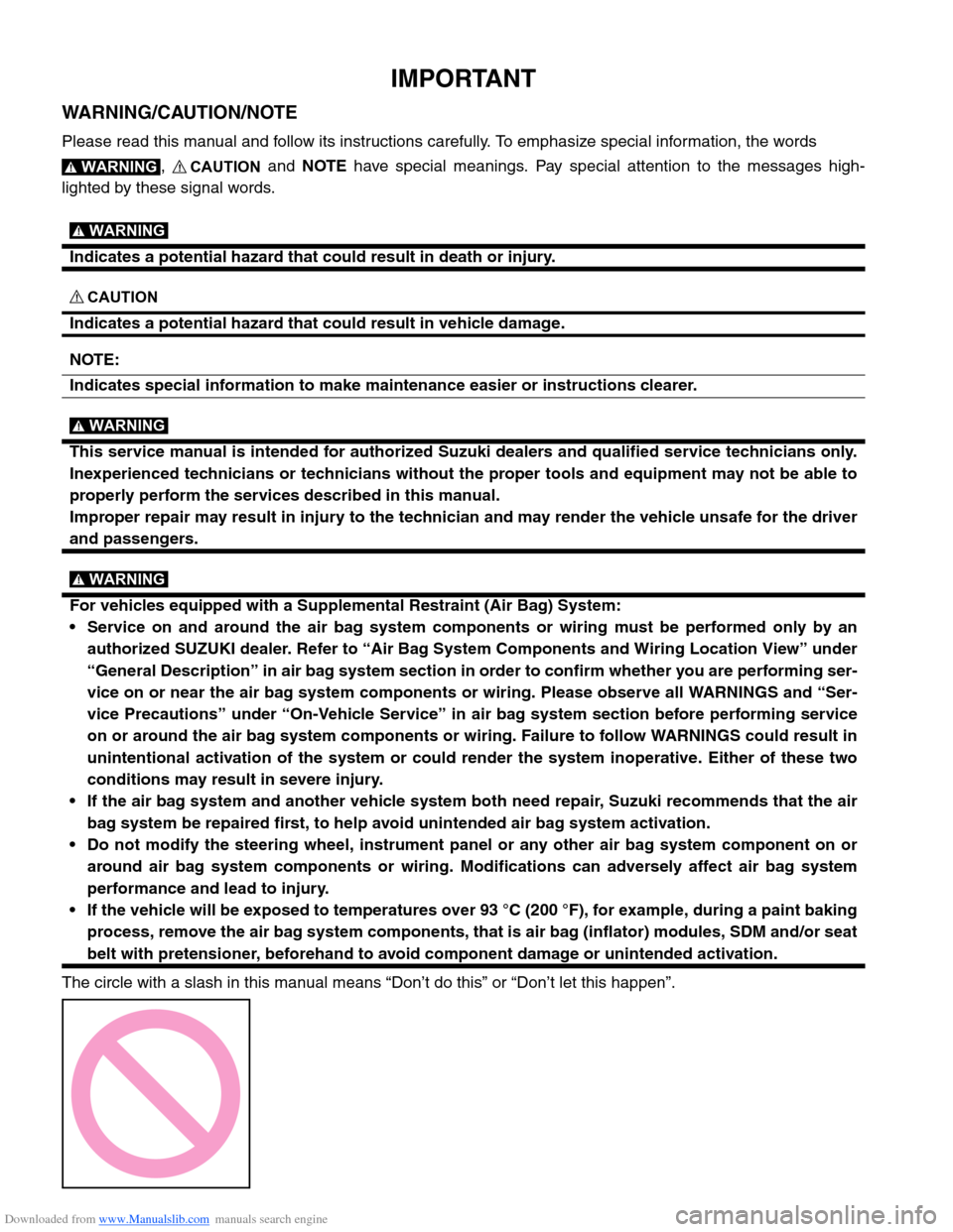
The circle with a slash in this manual me ans “Don’t do this” or “Don’t let this happen”.
WARNING!CAUTION!
Indicates a potential hazard that could result in death or injury.
WARNING!
Indicates a potential hazard that could result in vehicle damage.
CAUTION!
NOTE:
Indicates special information to make main tenance easier or instructions clearer.
This service manual is intended for authorized Su zuki dealers and qualified service technicians only.
Inexperienced technicians or technicians without the proper tools and equipment may not be able to
properly perform the services described in this manual.
Improper repair may result in injury to the technician and may render the vehicle unsafe for the driver
and passengers.
WARNING!
For vehicles equipped with a Supplemental Restraint (Air Bag) System:
• Service on and around the air bag system components or wiring must be performed only by an authorized SUZUKI dealer. Refer to “Air Bag System Components and Wiring Location View” under
“General Description” in air bag system section in order to confirm whether you are performing ser-
vice on or near the air bag system components or wiring. Please observe all WARNINGS and “Ser-
vice Precautions” under “On-Vehicl e Service” in air bag system section before performing service
on or around the air bag system components or wiring. Failure to follow WARNINGS could result in
unintentional activation of the system or could re nder the system inoperative. Either of these two
conditions may result in severe injury.
If the air bag system and another vehicle system both need repair, Suzuki recommends that the air
bag system be repaired first, to help av oid unintended air bag system activation.
Do not modify the steering wheel, instrument pa nel or any other air bag system component on or
around air bag system components or wiring. Modi fications can adversely affect air bag system
performance and lead to injury.
If the vehicle will be exposed to temperatures over 93 °C (200 °F), for example, during a paint baking
process, remove the air bag system components, th at is air bag (inflator) modules, SDM and/or seat
belt with pretensioner, beforehand to avoid component damage or unintended activation.
WARNING!
Page 4 of 1496

Downloaded from www.Manualslib.com manuals search engine 00
0
1
2
3
4
5
6
7
8
9
10
11
Vo l u m e 1
Precautions............................................................... 00-iPrecautions ............................................................ 00-1
General Information ................ ................................... 0-i
General Information ............................................... 0A-1
Maintenance and Lubricatio n ................................. 0B-1
Engine ......................................................................... 1-i Precautions .............................................................. 1-1
Engine General Information and Diagnosis ........... 1A-1
Aux. Emission Control Devices .............................. 1B-1
Engine Electrical Devices....................................... 1C-1
Engine Mechanical ................................................. 1D-1
Engine Lubrication System .................................... 1E-1
Engine Cooling System .......................................... 1F-1
Fuel System ...........................................................1G-1
Ignition System....................................................... 1H-1
Starting System ....................................................... 1I-1
Charging System.....................................................1J-1
Exhaust System ..................................................... 1K-1
Suspension ................................................................. 2-i Precautions .............................................................. 2-1
Suspension General Diagnosis .............................. 2A-1
Front Suspension ................................................... 2B-1
Rear Suspension................ .................................... 2C-1
Wheels and Tires ................................................... 2D-1
Driveline / Axle ........................................................... 3-i Precautions .............................................................. 3-1
Drive Shaft / Axle ................................................... 3A-1
Brakes ......................................................................... 4-i Precautions .............................................................. 4-1
Brake Control System and Diagnosis .................... 4A-1
Front Brakes........................................................... 4B-1
Rear Brakes ........................................................... 4C-1
Parking Brake......................................................... 4D-1
ABS ........................................................................ 4E-1
Electronic Stability Program ................................... 4F-1
Vo l u m e 2
Precautions ............................................................... 00-iPrecautions ............................................................ 00-1
Transmission / Transaxle .... ...................................... 5-i
Precautions .............................................................. 5-1
Automatic Transmission/Transaxle ........................ 5A-1
Manual Transmission/Transaxle ............................ 5B-1
Clutch .....................................................................5C-1
Steering ....................................................................... 6-i Precautions .............................................................. 6-1
Steering General Diagnosis ................................... 6A-1
Steering Wheel and Column .................................. 6B-1
Power Assisted Steering System ...........................6C-1
HVAC ........................................................................... 7-i Precautions .............................................................. 7-1
Heater and Ventilation............................................ 7A-1
Air Conditioning System ......................................... 7B-1
Restraint ...................................................................... 8-i Precautions .............................................................. 8-1
Seat Belts ............................................................... 8A-1
Air Bag System ...................................................... 8B-1
Body, Cab and Accessories .... .................................. 9-i
Precautions .............................................................. 9-1
Wiring Systems ...................................................... 9A-1
Lighting Systems .................................................... 9B-1
Instrumentation / Driver Info. / Horn .......................9C-1
Wipers / Washers ...................................................9D-1
Glass / Windows / Mirrors ...................................... 9E-1
Security and Locks ................................................. 9F-1
Seats ..................................................................... 9G-1
Interior Trim ............................................................9H-1
Hood / Fenders / Doors .......................................... 9J-1
Body Structure ....................................................... 9K-1
Paint / Coatings ...................................................... 9L-1
Exterior Trim .......................................................... 9M-1
Control Systems ....................................................... 10-i Precautions ............................................................ 10-1
Body Electrical Control Sy stem ............................ 10B-1
Immobilizer Control System .................................10C-1
Keyless Start System ........................................... 10E-1
TABLE OF CONTENTS
Page 6 of 1496
Downloaded from www.Manualslib.com manuals search engine 00-1 Precautions:
Precautions
Precautions
Precautions
Precautions for Vehicles Equipped with a
Supplemental Restraint (Air Bag) System
S7RS0B0000001
WARNING!
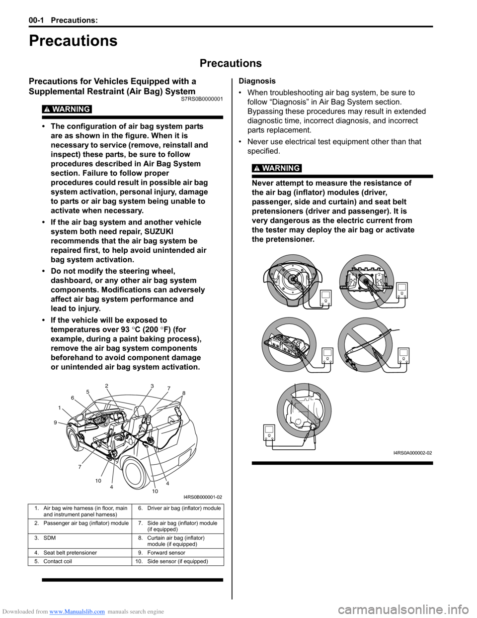
• The configuration of air bag system parts are as shown in the figure. When it is
necessary to service (remove, reinstall and
inspect) these parts, be sure to follow
procedures described in Air Bag System
section. Failure to follow proper
procedures could result in possible air bag
system activation, personal injury, damage
to parts or air bag system being unable to
activate when necessary.
• If the air bag system and another vehicle system both need repair, SUZUKI
recommends that the air bag system be
repaired first, to help avoid unintended air
bag system activation.
• Do not modify the steering wheel, dashboard, or any other air bag system
components. Modifications can adversely
affect air bag system performance and
lead to injury.
• If the vehicle will be exposed to temperatures over 93 °C (200 °F) (for
example, during a paint baking process),
remove the air bag system components
beforehand to avoid component damage
or unintended air bag system activation.
Diagnosis
• When troubleshooting air bag system, be sure to follow “Diagnosis” in Air Bag System section.
Bypassing these procedures may result in extended
diagnostic time, incorrect diagnosis, and incorrect
parts replacement.
• Never use electrical test equipment other than that specified.
WARNING!
Never attempt to measure the resistance of
the air bag (inflator) modules (driver,
passenger, side and curtain) and seat belt
pretensioners (driver and passenger). It is
very dangerous as the electric current from
the tester may deploy the air bag or activate
the pretensioner.
1. Air bag wire harness (in floor, main and instrument panel harness) 6. Driver air bag (inflator) module
2. Passenger air bag (inflator) module 7. Side air bag (inflator) module (if equipped)
3. SDM 8. Curtain air bag (inflator) module (if equipped)
4. Seat belt pretensioner 9. Forward sensor
5. Contact coil 10. Side sensor (if equipped)
1 2
3
4
4
5
6
7 7
8
9
10 10
I4RS0B000001-02
I4RS0A000002-02
Page 7 of 1496
Downloaded from www.Manualslib.com manuals search engine Precautions: 00-2
Servicing and Handling
WARNING!
Many of service procedures require
disconnection of “A/BAG” fuse and all air
bag (inflator) module(s) from initiator circuit
to avoid an accidental deployment.
Driver, Passenger, Side and Curtain Air Bag
(Inflator) Modules
• For handling and storage of a live air bag (inflator) module, select a place where the
ambient temperature below 65 °C (150 ° F),
without high humidity and away from
electric noise.
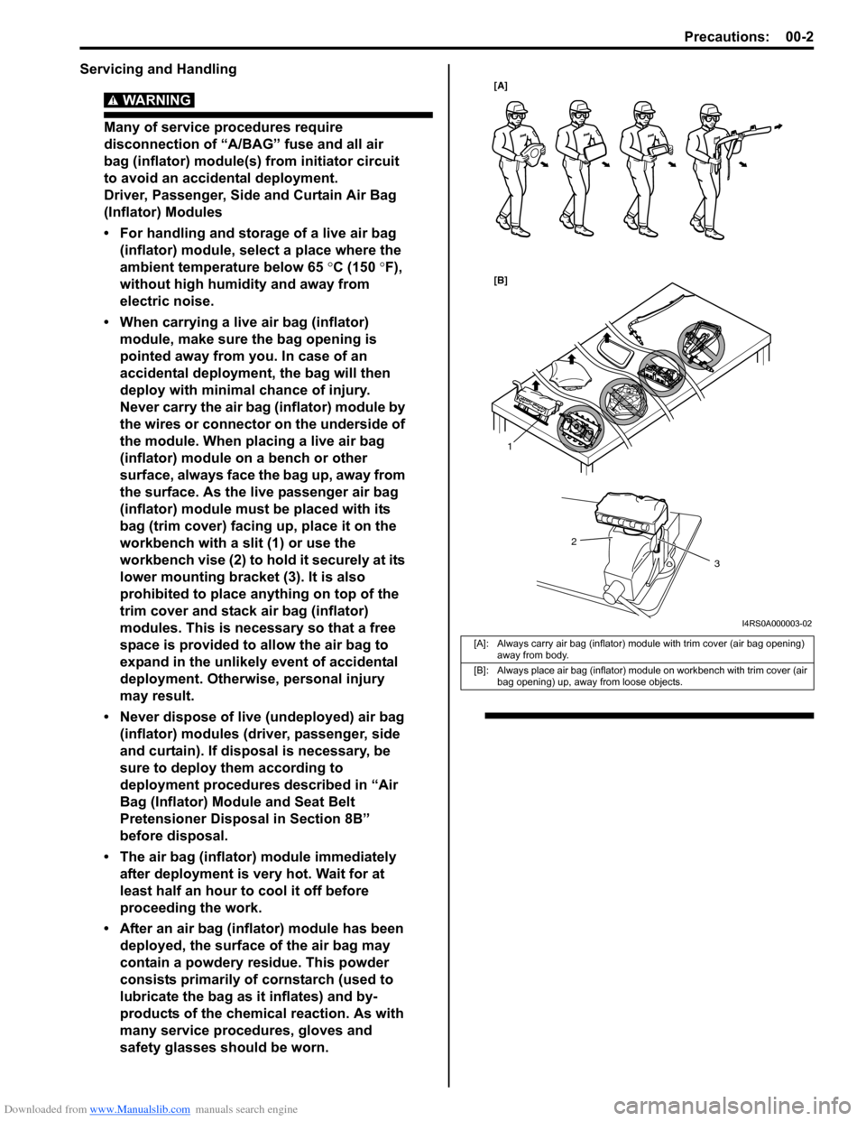
• When carrying a live air bag (inflator) module, make sure the bag opening is
pointed away from you. In case of an
accidental deployment, the bag will then
deploy with minimal chance of injury.
Never carry the air bag (inflator) module by
the wires or connector on the underside of
the module. When placing a live air bag
(inflator) module on a bench or other
surface, always face the bag up, away from
the surface. As the live passenger air bag
(inflator) module must be placed with its
bag (trim cover) facing up, place it on the
workbench with a slit (1) or use the
workbench vise (2) to hold it securely at its
lower mounting bracket (3). It is also
prohibited to place anything on top of the
trim cover and stack air bag (inflator)
modules. This is necessary so that a free
space is provided to allow the air bag to
expand in the unlikely event of accidental
deployment. Otherwise, personal injury
may result.
• Never dispose of live (undeployed) air bag (inflator) modules (driver, passenger, side
and curtain). If disposal is necessary, be
sure to deploy them according to
deployment procedures described in “Air
Bag (Inflator) Module and Seat Belt
Pretensioner Disposal in Section 8B”
before disposal.
• The air bag (inflator) module immediately
after deployment is very hot. Wait for at
least half an hour to cool it off before
proceeding the work.
• After an air bag (inflator) module has been deployed, the surface of the air bag may
contain a powdery residue. This powder
consists primarily of cornstarch (used to
lubricate the bag as it inflates) and by-
products of the chemical reaction. As with
many service procedures, gloves and
safety glasses should be worn.
[A]: Always carry air bag (inflator) module with trim cover (air bag opening) away from body.
[B]: Always place air bag (inflator) module on workbench with trim cover (air bag opening) up, away from loose objects.
1
2
3
[A]
[B]
I4RS0A000003-02
Page 8 of 1496
Downloaded from www.Manualslib.com manuals search engine 00-3 Precautions:
WARNING!
SDM
• For handling and storage of a SDM, select a place where the ambient temperature
below 65 °C (150 °F), without high humidity
and away from electric noise.
• During service procedures, be very careful when handling a Sensing and Diagnostic
Module (SDM). Never strike or jar the SDM.
• Never power up the air bag system when the SDM is not rigidly attached to the
vehicle. All SDM and mounting bracket
fasteners must be carefully torqued and
the arrow must be pointing toward the
front of the vehicle to ensure proper
operation of the air bag system.
The SDM could be activated when powered
while not rigidly att ached to the vehicle
which could cause deployment and result
in personal injury.
WARNING!
Driver and Passenger Seat Belt
Pretensioners
• For handling and storage of a live seat belt pretensioner, select a place where the
ambient temperature below 65 °C (150 ° F),
without high humidity and away from
electric noise.
• Never carry seat belt pretensioner by wire or connector of pretensioner. When
placing a live seat belt pretensioner on the
workbench or some place like that, never
put something on seat belt pretensioner.
Otherwise, personal injury may result.
• Never dispose of live (inactivated) seat belt pretensioners (drive and passenger). If
disposal is necessary, be sure to activate
them according to activation procedures
described in “Air Bag (Inflator) Module and
Seat Belt Pretensioner Disposal in Section
8B” before disposal.
• The seat belt pretensioner immediately after activation is very hot. Wait for at least
half an hour to cool it off before
proceeding the work.
• With many service procedures, gloves and safety glasses should be worn to prevent
any possible irritation of the skin or eyes.
• Even when the accident was light enough not to cause air bags to activate, be sure to inspect system
parts and other related parts according to instructions
under “Repair and Inspection Required after Accident
in Section 8B”.
• When servicing parts other than air bag system, if shocks may be applied to air bag system component
parts, remove those parts beforehand.
• When handling the air bag (inflator) modules (driver, passenger, side and curtain), seat belt pretensioners
(driver and passenger), forward sensor, side sensors
or SDM, be careful not to drop it or apply an impact to
it. If an excessive impact was applied, never attempt
disassembly or repair but replace it with a new one.
• When grease, cleaning agent, oil, water, etc. has got onto air bag (inflator) modules (driver, passenger, side
and curtain) or seat belt pretensioners (drive and
passenger), wipe off immediately with a dry cloth.
• Air bag wire harness is included in floor and instrument panel wire harnesses. Air bag wire
harness branched off from floor and instrument panel
wire harnesses can be identifie d easily as it is covered
with a yellow protection tube and it has yellow
connectors. Be very ca reful when handling it.
• When an open in air bag wire harness, damaged wire harness, connector or terminal is found, replace wire
harness, connectors and terminals as an assembly.
• Do not apply power to the air bag system unless all components are connected or a diagnostic flow
requests it, as this will set a DTC.
• Never use air bag system component parts from another vehicle.
• When using electric welding, be sure to disconnect all air bag (inflator) module connectors and pretensioner
connectors from air bag wire harness respectively.
• Never expose air bag system component parts directly to hot air (drying or baking the vehicle after
painting) or flames.
• WARNING / CAUTION labels are attached on each
part of air bag system components. Be sure to follow
the instructions.
• After vehicle is completely repaired, perform “Air Bag Diagnostic System Check in Section 8B”.
Page 9 of 1496
Downloaded from www.Manualslib.com manuals search engine Precautions: 00-4
General PrecautionsS7RS0B0000002
The WARNING and CAUTION describe some general
precautions that you should observe when servicing a
vehicle. These general precautions apply to many of the
service procedures, and they will not necessarily be
repeated with each procedure to which they apply.
WARNING!
• Whenever raising a vehicle for service, be sure to follow the instructions under
“Vehicle Lifting Points in Section 0A”.
• When it is necessary to do service work with the engine running, make sure that
the parking brake is set fully and the
transmission is in Neutral (for manual
transmission vehicles) or Park (for
automatic transmission vehicles), Keep
hands, hair, clothing, tools, etc. away from
the fan and belts when the engine is
running.
• When it is necessary to run the engine indoors, make sure that the exhaust gas is
forced outdoors.
• Do not perform service work in areas where combustible materials can come in
contact with a hot exhaust system. When
working with toxic or flammable materials
(such as gasoline and refrigerant), make
sure that the area you work in is well-
ventilated.
• To avoid getting burned, keep away from hot metal parts such as the radiator,
exhaust manifold, tail pipe, muffler, etc.
• New and used engine oil can be hazardous. Children and pets may be
harmed by swallowing new or used oil.
Keep new and used oil and used engine oil
filters away from children and pets.
Continuous contact with used engine oil
has been found to cause [skin] cancer in
laboratory animals. Brief contact with used
oil may irritate skin. To minimize your
exposure to used engine oil, wear a long-
sleeve shirt and moisture-proof gloves
(such as dish washing gloves) when
changing engine oil. If engine oil contacts
your skin, wash thoroughly with soap and
water. Launder any clothing or rags if wet
with oil, recycle or properly dispose of
used oil and filters. • Be sure to observe following instructions
when handling service materials such as
fuel, oil, fluid, coolant, grease, sealant,
thread lock cement, etc. Otherwise, your
health may be ruined.
– Whenever handling any of these service materials, wear safety glasses to protect
your eyes. If it gets into your eye, it may
cause inflammation.
– Whenever handling any of these service materials, wear moistu re-proof gloves to
protect your skin. If it adheres to your
skin, it may cause inflammation.
– Do not swallow any of these service materials. It would cause diarrhea or
nausea.
– Keep all these materials out of children’s reach.
• Make sure the bonnet is fully closed and latched before driving. If it is not, it can fly
up unexpectedly during driving,
obstructing your view and resulting in an
accident.
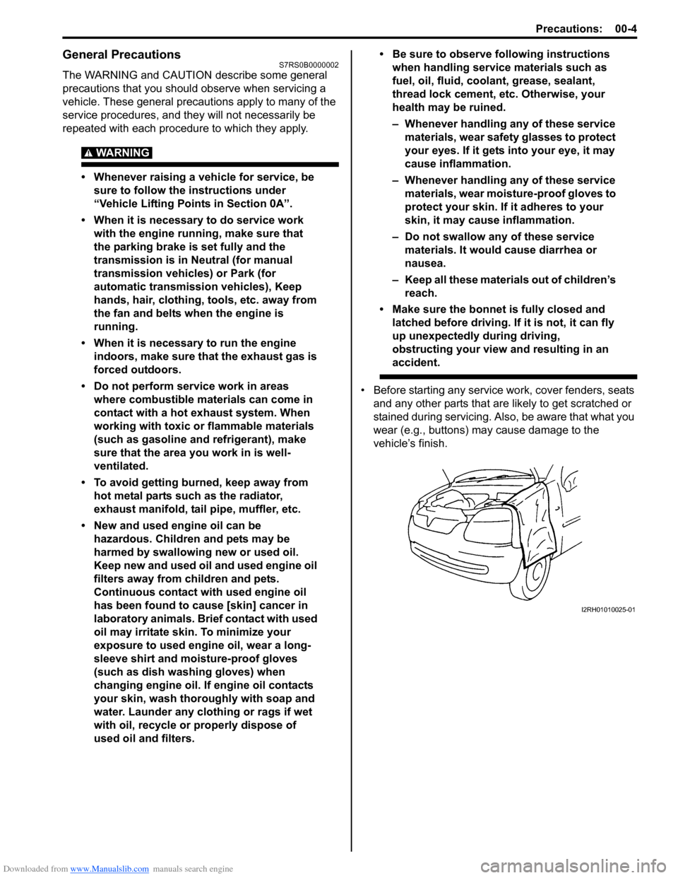
• Before starting any service work, cover fenders, seats and any other parts that are likely to get scratched or
stained during servicing. Also, be aware that what you
wear (e.g., buttons) ma y cause damage to the
vehicle’s finish.
I2RH01010025-01
Page 30 of 1496
![SUZUKI SWIFT 2006 2.G Service Workshop Manual Downloaded from www.Manualslib.com manuals search engine 0A-9 General Information:
[A]
12
4 5
6
7 8
9
3
I4RS0B010002-03
1. Air bag label on driver air bag (inflator) module 6. Air bag label on SDM
2 SUZUKI SWIFT 2006 2.G Service Workshop Manual Downloaded from www.Manualslib.com manuals search engine 0A-9 General Information:
[A]
12
4 5
6
7 8
9
3
I4RS0B010002-03
1. Air bag label on driver air bag (inflator) module 6. Air bag label on SDM
2](/img/20/7607/w960_7607-29.png)
Downloaded from www.Manualslib.com manuals search engine 0A-9 General Information:
[A]
12
4 5
6
7 8
9
3
I4RS0B010002-03
1. Air bag label on driver air bag (inflator) module 6. Air bag label on SDM
2. Air bag label on combination switch and contact coil assembly7. Pretensioner label on seat belt retractor
3. Air bag label on passenger air bag (inflator) module 8. Child seat label (if equipped)
4. Air bag label on side air bag (inflator) module (if equipped) 9. Side/Curtain air bag label on pillar (both right and left sides) (if equipped)
5. Air bag label on curtain air bag (inflator) module (if equipped) [A]: These labels are attached on vehicle equipped with air ba g system only.
Page 42 of 1496
Downloaded from www.Manualslib.com manuals search engine 0B-12 Maintenance and Lubrication:
HVAC Air Filter (If Equipped) InspectionS7RS0B0206032
1) Remove HVAC air filter from HVAC unit referring to
“HVAC Air Filter Removal and Installation (If
Equipped) in Section 7A”.
2) Check for dirt and dust. If HVAC air filter is excessively dirty, replace HVAC air filter with new
one. If not, go to next step.
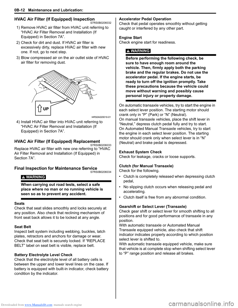
3) Blow compressed air on the air outlet side of HVAC air filter for removing dust.
4) Install HVAC air filter in to HVAC unit referring to
“HVAC Air Filter Removal and Installation (If
Equipped) in Section 7A”.
HVAC Air Filter (If Equipped) ReplacementS7RS0B0206033
Replace HVAC air filter with new one referring to “HVAC
Air Filter Removal and Installation (If Equipped) in
Section 7A”.
Final Inspection for Maintenance ServiceS7RS0B0206034
WARNING!
When carrying out road tests, select a safe
place where no man or no running vehicle is
seen so as to prevent any accident.
Seats
Check that seat slides smoot hly and locks securely at
any position. Also check that reclining mechanism of
front seat back allows it to be locked at any angle.
Seat Belt
Inspect belt system including webbing, buckles, latch
plates, retractors and anchors for damage or wear.
Check that seat belt is securely locked. If “REPLACE
BELT” label on seat belt is visible, replace belt.
Battery Electrolyte Level Check
Check that the electrolyte le vel of all battery cells is
between the upper and lower level lines on the case. If
battery is equipped with built-in indicator, check battery
condition by the indicator. Accelerator Pedal Operation
Check that pedal operates
smoothly without getting
caught or interfered by any other part.
Engine Start
Check engine start for readiness.
WARNING!
Before performing th e following check, be
sure to have enough room around the
vehicle. Then, firmly apply both the parking
brake and the regular brakes. Do not use the
accelerator pedal. If the engine starts, be
ready to turn off the ignition promptly. Take
these precautions because the vehicle could
move without warning and possibly cause
personal injury or property damage.
On automatic transaxle vehicles, try to start the engine in
each select lever position. The starting motor should
crank only in “P” (Park) or “N” (Neutral).
On manual transaxle vehicles, place the shift lever in
“Neutral,” depress clutch pedal fully and try to start.
On Automated Manual Transaxl e vehicles, try to start
the engine in each select le ver position. The starting
motor should crank only when select lever is in “N”
(Neutral) and brake pedal is depressed.
Exhaust System Check
Check for leakage, cracks or loose supports.
Clutch (for Manual Transaxle)
Check for the following.
• Clutch is completely released when depressing clutch pedal,
• No slipping clutch occurs when releasing pedal and accelerating.
• Clutch itself is free fr om any abnormal condition.
Gearshift or Select Lever (Transaxle)
Check gear shift or select lever for smooth shifting to all
positions and for good performance of transaxle in any
position.
With automatic transaxle or Automated Manual
Transaxle equipped vehicle, also check that shift
indicator indicates properly according to which position
select lever is shifted to.
With automatic transaxle equipped vehicle, make sure
that vehicle is at complete stop when shifting select lever
to “P” range position and release all brakes.
I4RS0A020018-01
Page 371 of 1496
Downloaded from www.Manualslib.com manuals search engine Engine Cooling System: 1F-8
Thermostat Removal and InstallationS7RS0B1606007
Removal1) Drain coolant referring to “Cooling System Draining”.
2) Remove intake manifold referring to “Intake Manifold Removal and Installa tion in Section 1D”.
3) Remove generator referring to “Generator Dismounting and Remounting in Section 1J”.
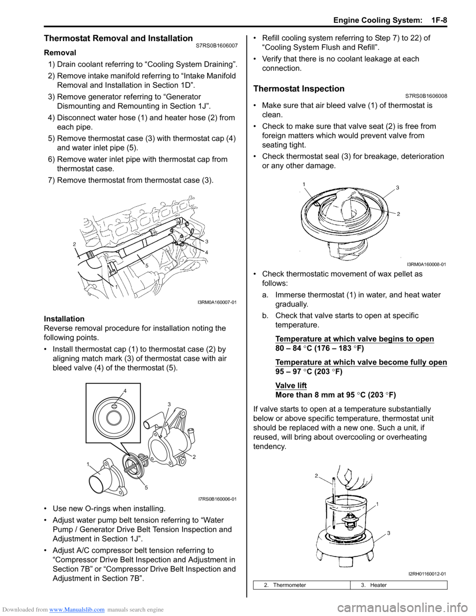
4) Disconnect water hose (1) and heater hose (2) from each pipe.
5) Remove thermostat case (3) with thermostat cap (4)
and water inlet pipe (5).
6) Remove water inlet pipe with thermostat cap from thermostat case.
7) Remove thermostat from thermostat case (3).
Installation
Reverse removal procedure for installation noting the
following points.
• Install thermostat cap (1) to thermostat case (2) by aligning match mark (3) of thermostat case with air
bleed valve (4) of the thermostat (5).
• Use new O-rings when installing.
• Adjust water pump belt tension referring to “Water Pump / Generator Drive Belt Tension Inspection and
Adjustment in Section 1J”.
• Adjust A/C compressor belt tension referring to “Compressor Drive Belt Inspection and Adjustment in
Section 7B” or “Compressor Drive Belt Inspection and
Adjustment in Section 7B”. • Refill cooling system referrin
g to Step 7) to 22) of
“Cooling System Flush and Refill”.
• Verify that there is no coolant leakage at each connection.
Thermostat InspectionS7RS0B1606008
• Make sure that air bleed valve (1) of thermostat is clean.
• Check to make sure that va lve seat (2) is free from
foreign matters which would prevent valve from
seating tight.
• Check thermostat seal (3) for breakage, deterioration or any other damage.
• Check thermostatic movement of wax pellet as follows:
a. Immerse thermostat (1) in water, and heat water gradually.
b. Check that valve starts to open at specific temperature.
Temperature at which valve begins to open
80 – 84 °C (176 – 183 °F)
Temperature at which valve become fully open
95 – 97 °C (203 °F)
Va l v e l i ft
More than 8 mm at 95 °C (203 ° F)
If valve starts to open at a temperature substantially
below or above specific temperature, thermostat unit
should be replaced with a new one. Such a unit, if
reused, will bring about ov ercooling or overheating
tendency.
I3RM0A160007-01
4
5 3
1 2
I7RS0B160006-01
2. Thermometer
3. Heater
I3RM0A160008-01
I2RH01160012-01
Page 471 of 1496
Downloaded from www.Manualslib.com manuals search engine Wheels and Tires: 2D-4
Radial Tire Waddle DescriptionS7RS0B2401005
Waddle is side to side movement at the front and/or rear
of the vehicle. It is caused by the steel belt not being
straight within the tire. It is most noticeable at a low
speed, 8 to 48 kph (5 to 30 mph).
It is possible to locate the f aulty tire by road testing the
vehicle. If it is on the rear , the rear end of the vehicle
shakes from side to side or “waddles”. To the driver in
the seat, it feels as though someone is pushing on the
side of vehicle.
If the faulty tire is on the front, waddling is more visual.
The front sheet metal appears to be moving back and
forth and the driver feels as though he is at the pivot
point in vehicle.
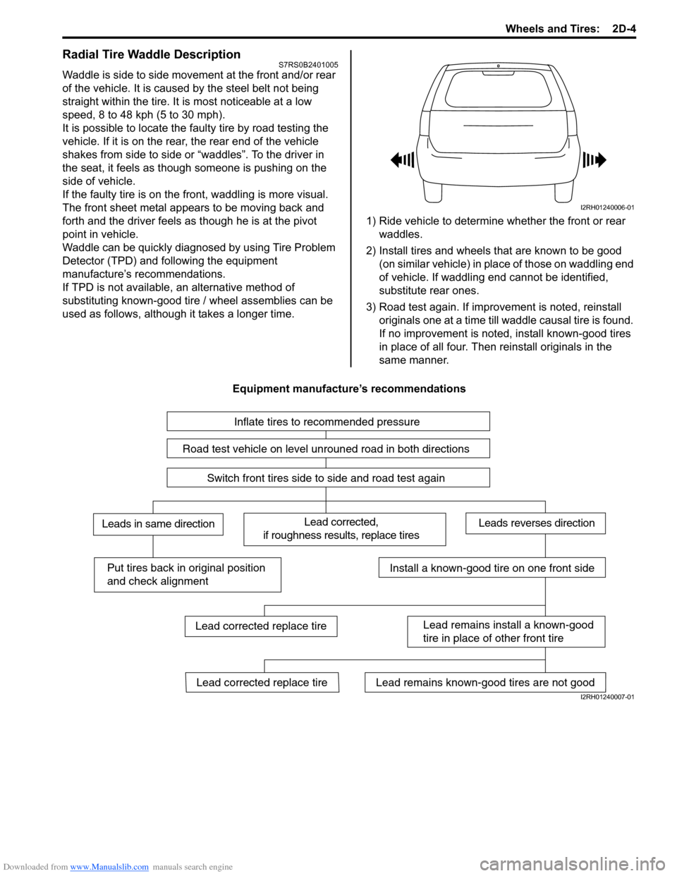
Waddle can be quickly diagnosed by using Tire Problem
Detector (TPD) and following the equipment
manufacture’s recommendations.
If TPD is not available, an alternative method of
substituting known-good tire / wheel assemblies can be
used as follows, although it takes a longer time. 1) Ride vehicle to determine whether the front or rear
waddles.
2) Install tires and wheels that are known to be good (on similar vehicle) in place of those on waddling end
of vehicle. If waddling end cannot be identified,
substitute rear ones.
3) Road test again. If improvement is noted, reinstall originals one at a time till w addle causal tire is found.
If no improvement is noted, install known-good tires
in place of all four. Then reinstall originals in the
same manner.
Equipment manufacture’s recommendations
I2RH01240006-01
Inflate tires to recommended pressure
Road test vehicle on level unrouned road in both directions
Switch front tires side to side and road test again
Lead corrected,
if roughness results, replace tiresLeads in same directionLeads reverses direction
Put tires back in original position
and check alignmentInstall a known-good tire on one front side
Lead remains install a known-good
tire in place of other front tire
Lead remains known-good tires are not goodLead corrected replace tire
Lead corrected replace tire
I2RH01240007-01