Air pressure SUZUKI SWIFT 2006 2.G Service Owners Manual
[x] Cancel search | Manufacturer: SUZUKI, Model Year: 2006, Model line: SWIFT, Model: SUZUKI SWIFT 2006 2.GPages: 1496, PDF Size: 34.44 MB
Page 681 of 1496
Downloaded from www.Manualslib.com manuals search engine Automatic Transmission/Transaxle: 5A-37
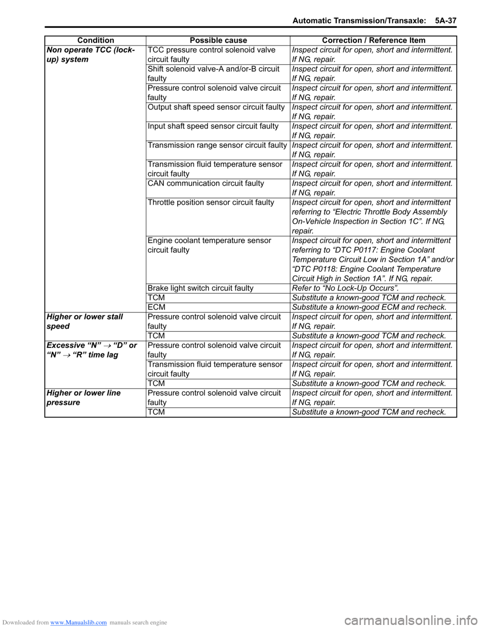
Non operate TCC (lock-
up) systemTCC pressure control solenoid valve
circuit faulty Inspect circuit for open, short and intermittent.
If NG, repair.
Shift solenoid valve-A and/or-B circuit
faulty Inspect circuit for open, short and intermittent.
If NG, repair.
Pressure control solenoid valve circuit
faulty Inspect circuit for open, short and intermittent.
If NG, repair.
Output shaft speed sensor circuit faulty Inspect circuit for open, short and intermittent.
If NG, repair.
Input shaft speed sensor circuit faulty Inspect circuit for open, short and intermittent.
If NG, repair.
Transmission range sensor circuit faulty Inspect circuit for open, short and intermittent.
If NG, repair.
Transmission fluid temperature sensor
circuit faulty Inspect circuit for open, short and intermittent.
If NG, repair.
CAN communication circuit faulty Inspect circuit for open, short and intermittent.
If NG, repair.
Throttle position sensor circuit faulty Inspect circuit for open, short and intermittent
referring to “Electric Throttle Body Assembly
On-Vehicle Inspection in Section 1C”. If NG,
repair.
Engine coolant temperature sensor
circuit faulty Inspect circuit for open, short and intermittent
referring to “DTC P0117: Engine Coolant
Temperature Circuit Low
in Section 1A” and/or
“DTC P0118: Engine Coolant Temperature
Circuit High in Section 1A”. If NG, repair.
Brake light switch circuit faulty Refer to “No Lock-Up Occurs”.
TCM Substitute a known-good TCM and recheck.
ECM Substitute a known-good ECM and recheck.
Higher or lower stall
speed Pressure control solenoid valve circuit
faulty Inspect circuit for open, short and intermittent.
If NG, repair.
TCM Substitute a known-good TCM and recheck.
Excessive “N”
→ “D” or
“N”
→ “R” time lag Pressure control solenoid valve circuit
faulty Inspect circuit for open, short and intermittent.
If NG, repair.
Transmission fluid temperature sensor
circuit faulty Inspect circuit for open, short and intermittent.
If NG, repair.
TCM Substitute a known-good TCM and recheck.
Higher or lower line
pressure Pressure control solenoid valve circuit
faulty Inspect circuit for open, short and intermittent.
If NG, repair.
TCM Substitute a known-good TCM and recheck.
Condition Possible cause Correction / Reference Item
Page 682 of 1496
Downloaded from www.Manualslib.com manuals search engine 5A-38 Automatic Transmission/Transaxle:
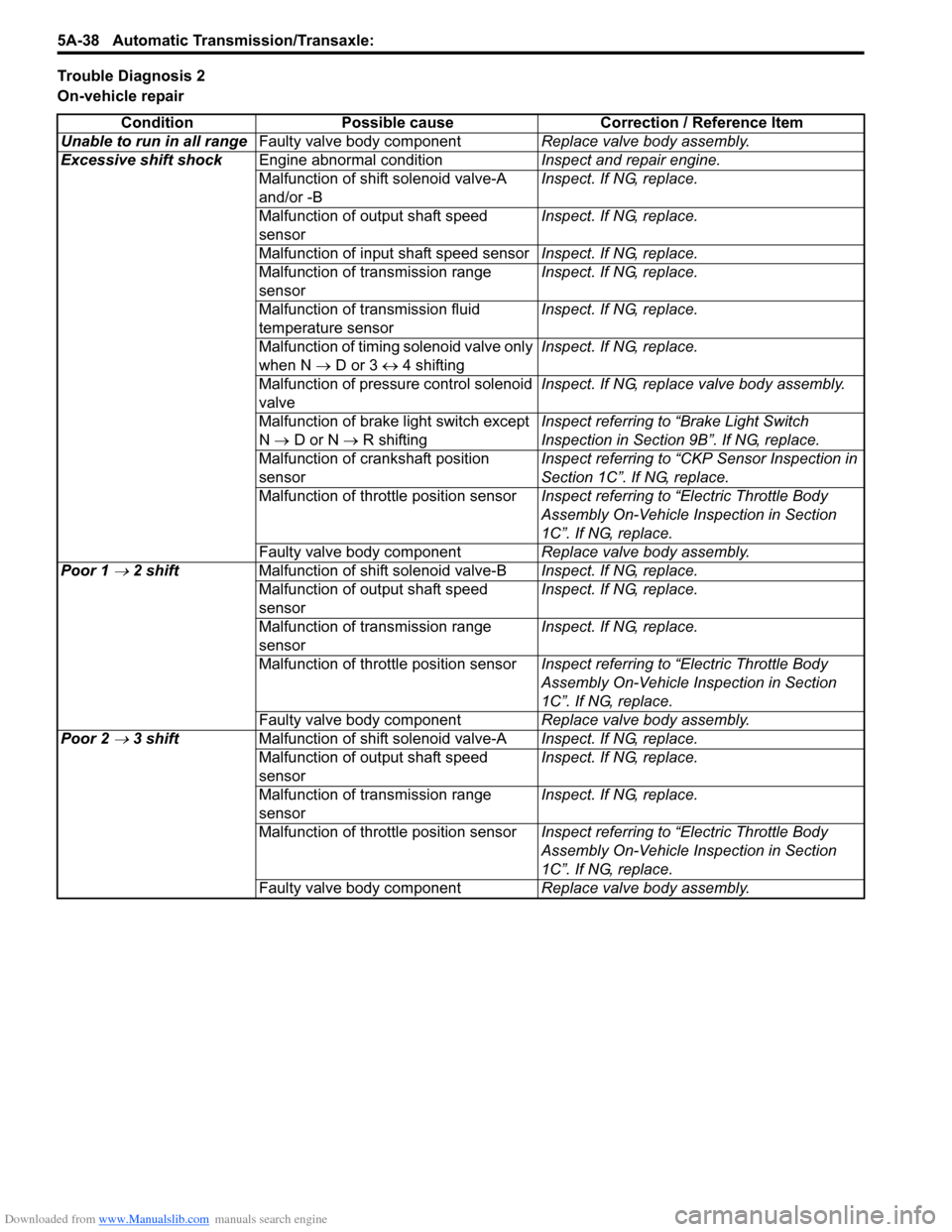
Trouble Diagnosis 2
On-vehicle repair
Condition Possible cause Correction / Reference Item
Unable to run in all range Faulty valve body component Replace valve body assembly.
Excessive shift shock Engine abnormal condition Inspect and repair engine.
Malfunction of shift solenoid valve-A
and/or -B Inspect. If NG, replace.
Malfunction of output shaft speed
sensor Inspect. If NG, replace.
Malfunction of input shaft speed sensor Inspect. If NG, replace.
Malfunction of transmission range
sensor Inspect. If NG, replace.
Malfunction of transmission fluid
temperature sensor Inspect. If NG, replace.
Malfunction of timing solenoid valve only
when N → D or 3 ↔ 4 shifting Inspect. If NG, replace.
Malfunction of pressure control solenoid
valve Inspect. If NG, replace valve body assembly.
Malfunction of brake light switch except
N → D or N → R shifting Inspect referring to “Brake Light Switch
Inspection in Section 9B”. If NG, replace.
Malfunction of crankshaft position
sensor Inspect referring to “CKP Sensor Inspection in
Section 1C”. If NG, replace.
Malfunction of throttle position sensor Inspect referring to “Electric Throttle Body
Assembly On-Vehicle Inspection in Section
1C”. If NG, replace.
Faulty valve body component Replace valve body assembly.
Poor 1
→ 2 shift Malfunction of shift solenoid valve-B Inspect. If NG, replace.
Malfunction of output shaft speed
sensor Inspect. If NG, replace.
Malfunction of transmission range
sensor Inspect. If NG, replace.
Malfunction of throttle position sensor Inspect referring to “Electric Throttle Body
Assembly On-Vehicle Inspection in Section
1C”. If NG, replace.
Faulty valve body component Replace valve body assembly.
Poor 2
→ 3 shift Malfunction of shift solenoid valve-A Inspect. If NG, replace.
Malfunction of output shaft speed
sensor Inspect. If NG, replace.
Malfunction of transmission range
sensor Inspect. If NG, replace.
Malfunction of throttle position sensor Inspect referring to “Electric Throttle Body
Assembly On-Vehicle Inspection in Section
1C”. If NG, replace.
Faulty valve body component Replace valve body assembly.
Page 683 of 1496
Downloaded from www.Manualslib.com manuals search engine Automatic Transmission/Transaxle: 5A-39
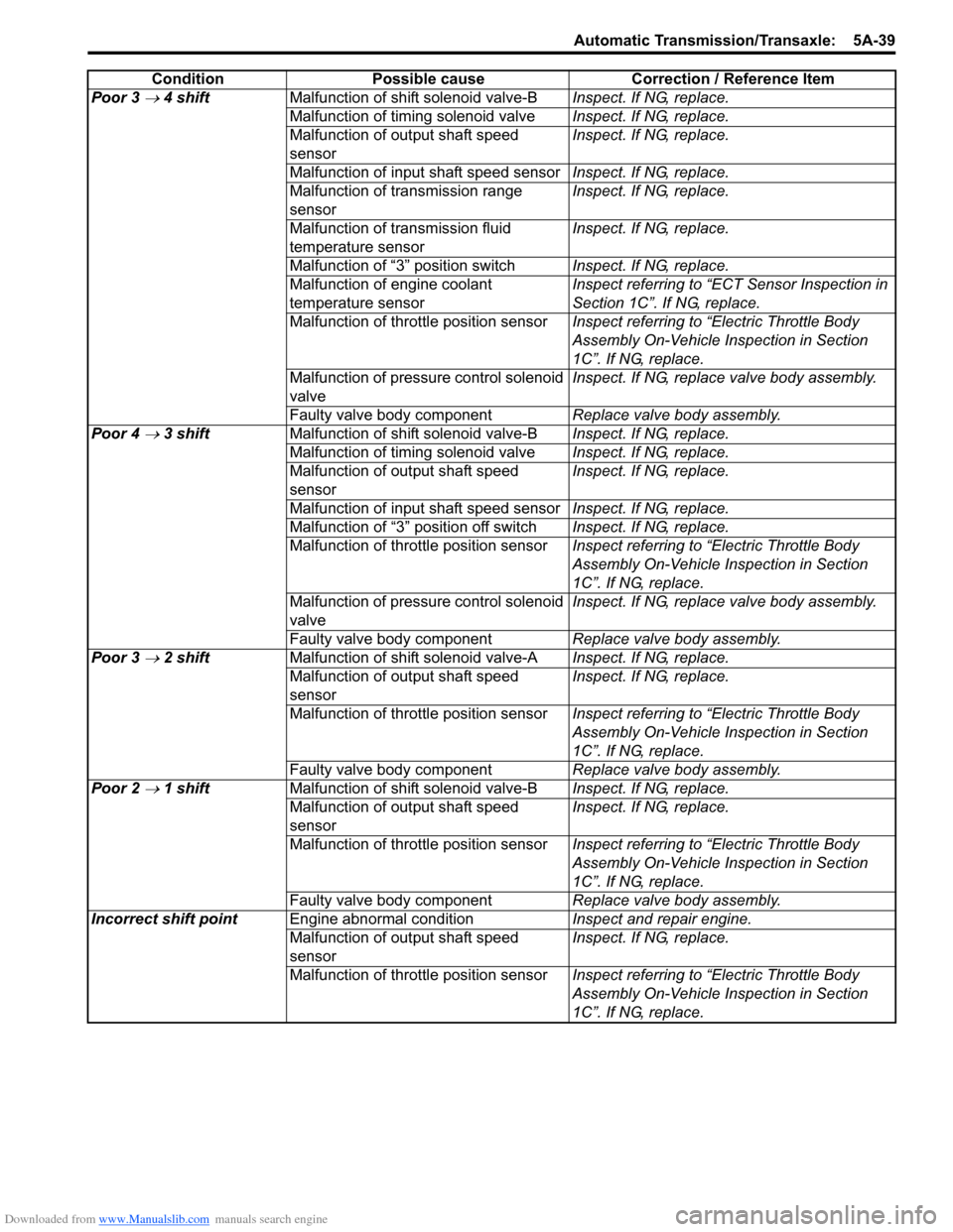
Poor 3 → 4 shiftMalfunction of shift solenoid valve-B Inspect. If NG, replace.
Malfunction of timing solenoid valve Inspect. If NG, replace.
Malfunction of output shaft speed
sensor Inspect. If NG, replace.
Malfunction of input shaft speed sensor Inspect. If NG, replace.
Malfunction of transmission range
sensor Inspect. If NG, replace.
Malfunction of transmission fluid
temperature sensor Inspect. If NG, replace.
Malfunction of “3” position switch Inspect. If NG, replace.
Malfunction of engine coolant
temperature sensor Inspect referring to “ECT Sensor Inspection in
Section 1C”. If NG, replace.
Malfunction of throttle position sensor Inspect referring to “Electric Throttle Body
Assembly On-Vehicle Inspection in Section
1C”. If NG, replace.
Malfunction of pressure control solenoid
valve Inspect. If NG, replace valve body assembly.
Faulty valve body component Replace valve body assembly.
Poor 4
→ 3 shift Malfunction of shift solenoid valve-B Inspect. If NG, replace.
Malfunction of timing solenoid valve Inspect. If NG, replace.
Malfunction of output shaft speed
sensor Inspect. If NG, replace.
Malfunction of input shaft speed sensor Inspect. If NG, replace.
Malfunction of “3” position off switch Inspect. If NG, replace.
Malfunction of throttle position sensor Inspect referring to “Electric Throttle Body
Assembly On-Vehicle Inspection in Section
1C”. If NG, replace.
Malfunction of pressure control solenoid
valve Inspect. If NG, replace valve body assembly.
Faulty valve body component Replace valve body assembly.
Poor 3
→ 2 shift Malfunction of shift solenoid valve-A Inspect. If NG, replace.
Malfunction of output shaft speed
sensor Inspect. If NG, replace.
Malfunction of throttle position sensor Inspect referring to “Electric Throttle Body
Assembly On-Vehicle Inspection in Section
1C”. If NG, replace.
Faulty valve body component Replace valve body assembly.
Poor 2
→ 1 shift Malfunction of shift solenoid valve-B Inspect. If NG, replace.
Malfunction of output shaft speed
sensor Inspect. If NG, replace.
Malfunction of throttle position sensor Inspect referring to “Electric Throttle Body
Assembly On-Vehicle Inspection in Section
1C”. If NG, replace.
Faulty valve body component Replace valve body assembly.
Incorrect shift point Engine abnormal condition Inspect and repair engine.
Malfunction of output shaft speed
sensor Inspect. If NG, replace.
Malfunction of throttle position sensor Inspect referring to “Electric Throttle Body
Assembly On-Vehicle Inspection in Section
1C”. If NG, replace.
Condition Possible cause Correction / Reference Item
Page 684 of 1496
Downloaded from www.Manualslib.com manuals search engine 5A-40 Automatic Transmission/Transaxle:
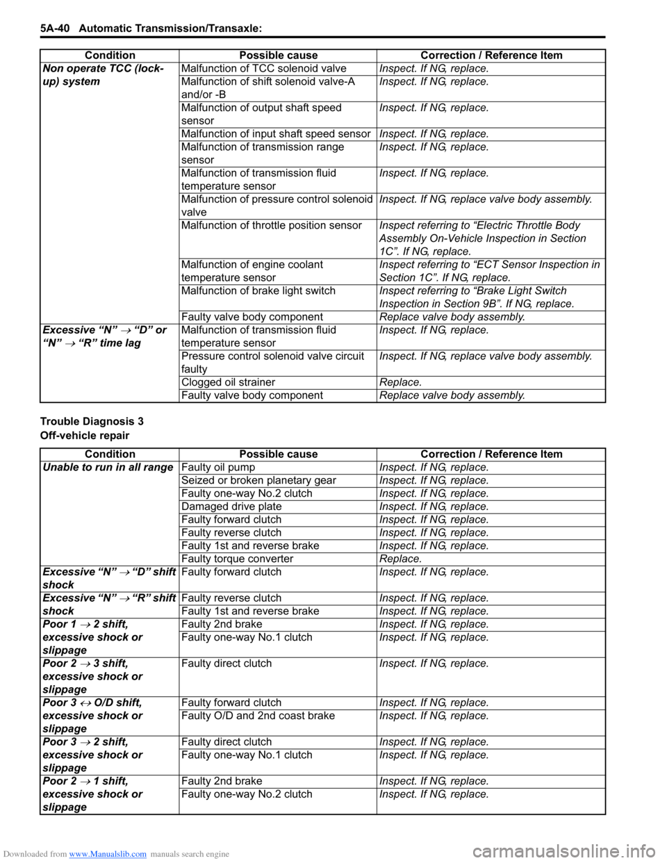
Trouble Diagnosis 3
Off-vehicle repairNon operate TCC (lock-
up) system
Malfunction of TCC solenoid valve
Inspect. If NG, replace.
Malfunction of shift solenoid valve-A
and/or -B Inspect. If NG, replace.
Malfunction of output shaft speed
sensor Inspect. If NG, replace.
Malfunction of input shaft speed sensor Inspect. If NG, replace.
Malfunction of transmission range
sensor Inspect. If NG, replace.
Malfunction of transmission fluid
temperature sensor Inspect. If NG, replace.
Malfunction of pressure control solenoid
valve Inspect. If NG, replace valve body assembly.
Malfunction of throttle position sensor Inspect referring to “Electric Throttle Body
Assembly On-Vehicle Inspection in Section
1C”. If NG, replace.
Malfunction of engine coolant
temperature sensor Inspect referring to “ECT Sensor Inspection in
Section 1C”. If NG, replace.
Malfunction of brake light switch Inspect referring to “Brake Light Switch
Inspection in Section 9B”. If NG, replace.
Faulty valve body component Replace valve body assembly.
Excessive “N”
→ “D” or
“N”
→ “R” time lag Malfunction of transmission fluid
temperature sensor Inspect. If NG, replace.
Pressure control solenoid valve circuit
faulty Inspect. If NG, replace valve body assembly.
Clogged oil strainer Replace.
Faulty valve body component Replace valve body assembly.
Condition Possible cause Correction / Reference Item
Condition
Possible cause Correction / Reference Item
Unable to run in all range Faulty oil pump Inspect. If NG, replace.
Seized or broken planetary gear Inspect. If NG, replace.
Faulty one-way No.2 clutch Inspect. If NG, replace.
Damaged drive plate Inspect. If NG, replace.
Faulty forward clutch Inspect. If NG, replace.
Faulty reverse clutch Inspect. If NG, replace.
Faulty 1st and reverse brake Inspect. If NG, replace.
Faulty torque converter Replace.
Excessive “N”
→ “D” shift
shock Faulty forward clutch
Inspect. If NG, replace.
Excessive “N”
→ “R” shift
shock Faulty reverse clutch
Inspect. If NG, replace.
Faulty 1st and reverse brake Inspect. If NG, replace.
Poor 1
→ 2 shift,
excessive shock or
slippage Faulty 2nd brake
Inspect. If NG, replace.
Faulty one-way No.1 clutch Inspect. If NG, replace.
Poor 2
→ 3 shift,
excessive shock or
slippage Faulty direct clutch
Inspect. If NG, replace.
Poor 3
↔ O/D shift,
excessive shock or
slippage Faulty forward clutch
Inspect. If NG, replace.
Faulty O/D and 2nd coast brake Inspect. If NG, replace.
Poor 3
→ 2 shift,
excessive shock or
slippage Faulty direct clutch
Inspect. If NG, replace.
Faulty one-way No.1 clutch Inspect. If NG, replace.
Poor 2
→ 1 shift,
excessive shock or
slippage Faulty 2nd brake
Inspect. If NG, replace.
Faulty one-way No.2 clutch Inspect. If NG, replace.
Page 703 of 1496
Downloaded from www.Manualslib.com manuals search engine Automatic Transmission/Transaxle: 5A-59
DTC TroubleshootingStep Action Yes No 1 Was “A/T System Check” performed? Go to Step 2. Go to “A/T System
Check”.
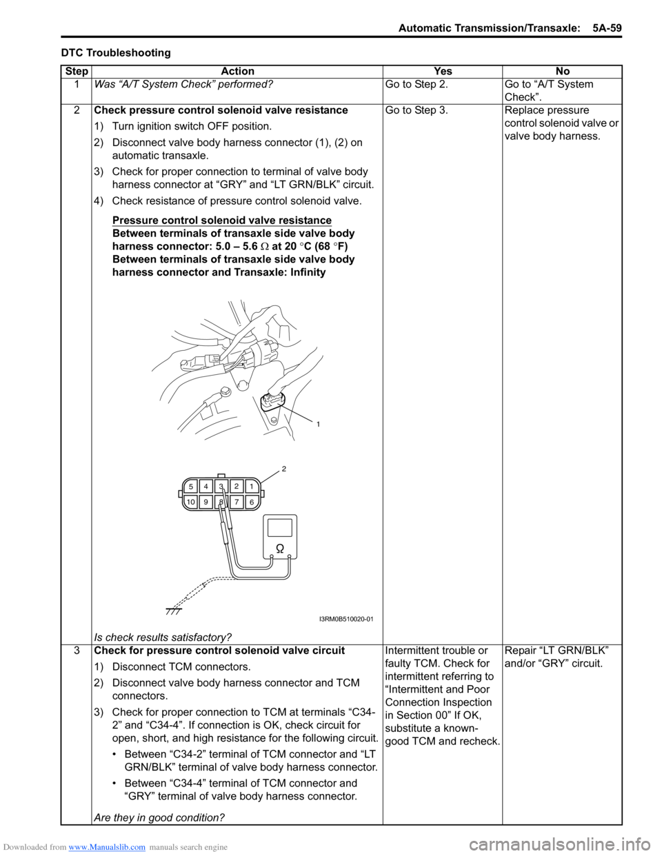
2 Check pressure control solenoid valve resistance
1) Turn ignition switch OFF position.
2) Disconnect valve body harness connector (1), (2) on
automatic transaxle.
3) Check for proper connection to terminal of valve body harness connector at “GRY” and “LT GRN/BLK” circuit.
4) Check resistance of pressure control solenoid valve.
Pressure control solenoid valve resistance
Between terminals of transaxle side valve body
harness connector: 5.0 – 5.6 Ω at 20 °C (68 °F)
Between terminals of transaxle side valve body
harness connector and Transaxle: Infinity
Is check results satisfactory? Go to Step 3. Replace pressure
control solenoid valve or
valve body harness.
3 Check for pressure control solenoid valve circuit
1) Disconnect TCM connectors.
2) Disconnect valve body harness connector and TCM
connectors.
3) Check for proper connection to TCM at terminals “C34- 2” and “C34-4”. If connection is OK, check circuit for
open, short, and high resistance for the following circuit.
• Between “C34-2” terminal of TCM connector and “LT GRN/BLK” terminal of valve body harness connector.
• Between “C34-4” terminal of TCM connector and “GRY” terminal of valve body harness connector.
Are they in good condition? Intermittent trouble or
faulty TCM. Check for
intermittent referring to
“Intermittent and Poor
Connection Inspection
in Section 00” If OK,
substitute a known-
good TCM and recheck.
Repair “LT GRN/BLK”
and/or “GRY” circuit.
1
6
7
89
10 5
43 2
1
2
I3RM0B510020-01
Page 721 of 1496
Downloaded from www.Manualslib.com manuals search engine Automatic Transmission/Transaxle: 5A-77
DTC TroubleshootingStep Action Yes No 1 Was “A/T System Check” performed? Go to Step 2. Go to “A/T System
Check”.
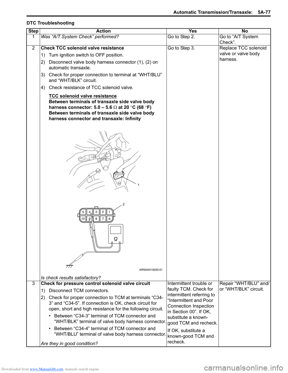
2 Check TCC solenoid valve resistance
1) Turn ignition switch to OFF position.
2) Disconnect valve body harness connector (1), (2) on
automatic transaxle.
3) Check for proper connection to terminal at “WHT/BLU” and “WHT/BLK” circuit.
4) Check resistance of TCC solenoid valve.
TCC solenoid valve resistance
Between terminals of transaxle side valve body
harness connector: 5.0 – 5.6 Ω at 20 °C (68 °F)
Between terminals of transaxle side valve body
harness connector and transaxle: Infinity
Is check results satisfactory? Go to Step 3. Replace TCC solenoid
valve or valve body
harness.
3 Check for pressure control solenoid valve circuit
1) Disconnect TCM connectors.
2) Check for proper connection to TCM at terminals “C34-
3” and “C34-5”. If connection is OK, check circuit for
open, short and high resistance for the following circuit.
• Between “C34-3” terminal of TCM connector and “WHT/BLK” terminal of valve body harness connector.
• Between “C34-4” terminal of TCM connector and “WHT/BLU” terminal of valve body harness connector.
Are they in good condition? Intermittent trouble or
faulty TCM. Check for
intermittent referring to
“Intermittent and Poor
Connection Inspection
in Section 00”. If OK,
substitute a known-
good TCM and recheck.
If OK, substitute a
known-good TCM and
recheck.
Repair “WHT/BLU” and/
or “WHT/BLK” circuit.
1
6
7
89
10 5
43 2
1
2
I4RS0A510020-01
Page 746 of 1496
Downloaded from www.Manualslib.com manuals search engine 5A-102 Automatic Transmission/Transaxle:
Operation Check
Check pressure control solenoid valves (Pressure
control solenoid and TCC pressure control solenoid)
operation in the either manner of the following.
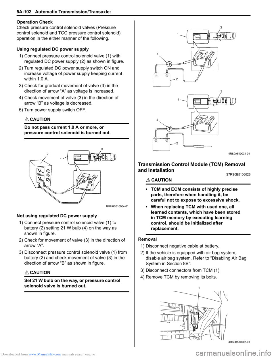
Using regulated DC power supply
1) Connect pressure contro l solenoid valve (1) with
regulated DC power supply (2) as shown in figure.
2) Turn regulated DC power supply switch ON and increase voltage of power supply keeping current
within 1.0 A.
3) Check for gradual movement of valve (3) in the direction of arrow “A” as voltage is increased.
4) Check movement of valve (3) in the direction of arrow “B” as voltage is decreased.
5) Turn power supply switch OFF.
CAUTION!
Do not pass current 1.0 A or more, or
pressure control solenoid is burned out.
Not using regulated DC power supply 1) Connect pressure control solenoid valve (1) to battery (2) setting 21 W bulb (4) on the way as
shown in figure.
2) Check for movement of valve (3) in the direction of arrow “A”.
3) Disconnect pressure control solenoid valve (1) from battery (2) and check movement of valve (3) in the
direction of arrow “B” as shown in figure.
CAUTION!
Set 21 W bulb on the way, or pressure control
solenoid valve is burned out.
Transmission Control Module (TCM) Removal
and Installation
S7RS0B5106026
CAUTION!
• TCM and ECM consists of highly precise
parts, therefore when handling it, be
careful not to expose to excessive shock.
• When replacing TCM with used one, all learned contents, which have been stored
in TCM memory by executing learning
control, should be initialized after
replacement.
Removal
1) Disconnect negative cable at battery.
2) If the vehicle is equipped with air bag system, disable air bag system. Refer to “Disabling Air Bag
System in Section 8B”.
3) Disconnect connectors from TCM (1).
4) Remove TCM by removing its bolts.
I2RH0B510064-01
I4RS0A510031-01
1
I4RS0B510007-01
Page 756 of 1496
Downloaded from www.Manualslib.com manuals search engine 5A-112 Automatic Transmission/Transaxle:
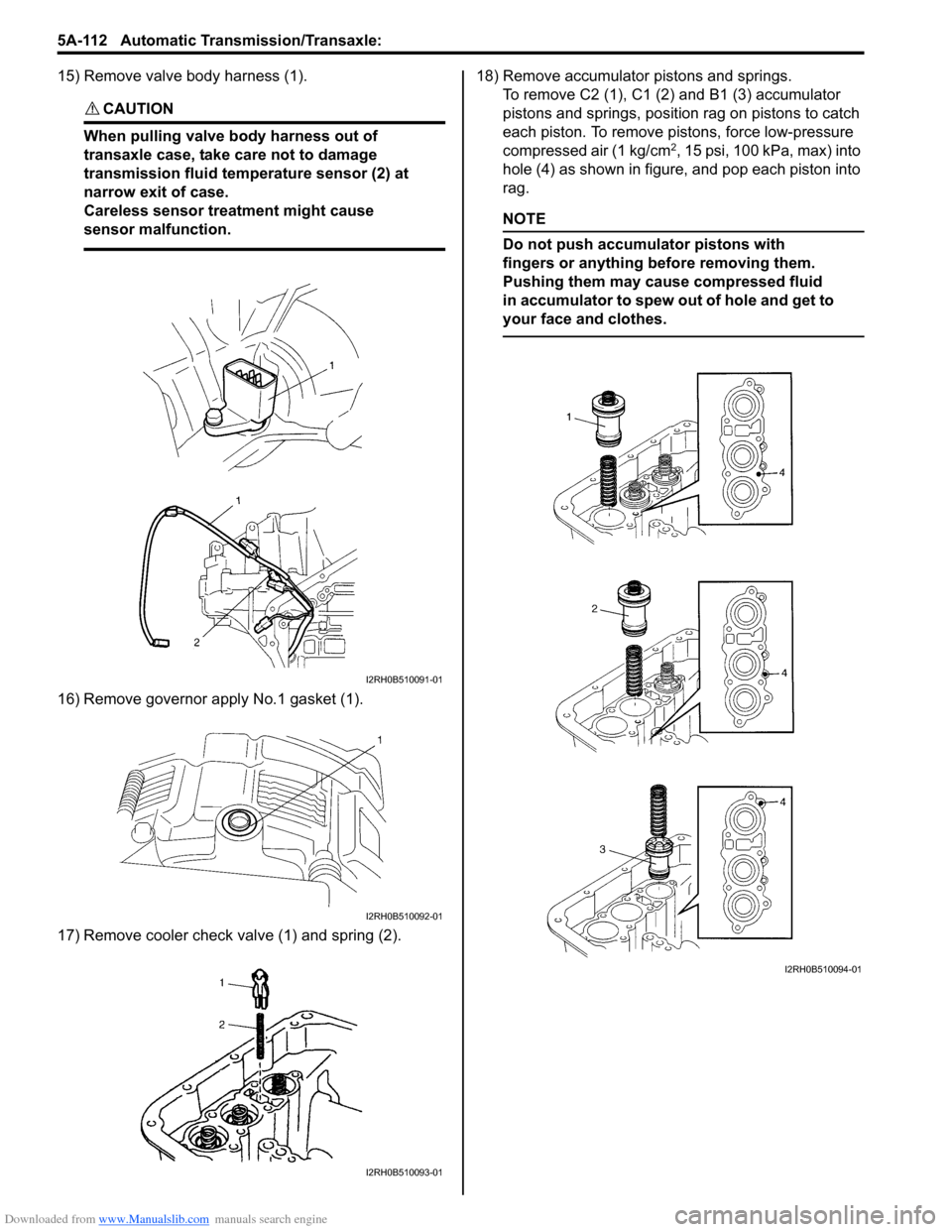
15) Remove valve body harness (1).
CAUTION!
When pulling valve body harness out of
transaxle case, take care not to damage
transmission fluid temperature sensor (2) at
narrow exit of case.
Careless sensor treatment might cause
sensor malfunction.
16) Remove governor apply No.1 gasket (1).
17) Remove cooler check valve (1) and spring (2).18) Remove accumulator pistons and springs.
To remove C2 (1), C1 (2) and B1 (3) accumulator
pistons and springs, position rag on pistons to catch
each piston. To remove pistons, force low-pressure
compressed air (1 kg/cm
2, 15 psi, 100 kPa, max) into
hole (4) as shown in figure, and pop each piston into
rag.
NOTE
Do not push accumulator pistons with
fingers or anything before removing them.
Pushing them may cause compressed fluid
in accumulator to spew out of hole and get to
your face and clothes.
I2RH0B510091-01
I2RH0B510092-01
I2RH0B510093-01
I2RH0B510094-01
Page 771 of 1496
Downloaded from www.Manualslib.com manuals search engine Automatic Transmission/Transaxle: 5A-127
Direct Clutch Assembly InspectionS7RS0B5106040
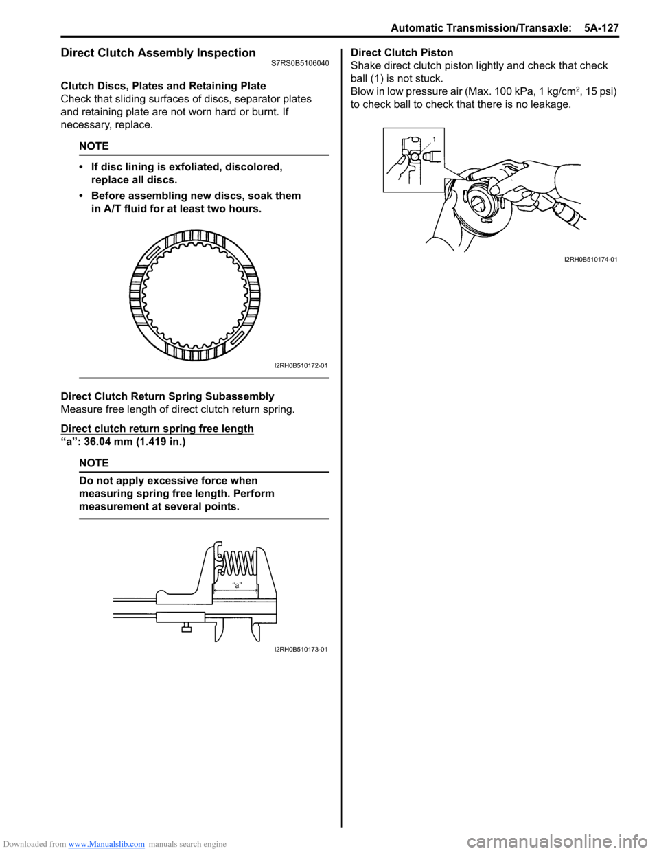
Clutch Discs, Plates and Retaining Plate
Check that sliding surfaces of discs, separator plates
and retaining plate are not worn hard or burnt. If
necessary, replace.
NOTE
• If disc lining is exfoliated, discolored, replace all discs.
• Before assembling new discs, soak them in A/T fluid for at least two hours.
Direct Clutch Return Spring Subassembly
Measure free length of direct clutch return spring.
Direct clutch return spring free length
“a”: 36.04 mm (1.419 in.)
NOTE
Do not apply excessive force when
measuring spring free length. Perform
measurement at several points.
Direct Clutch Piston
Shake direct clutch piston lightly and check that check
ball (1) is not stuck.
Blow in low pressure air (Max. 100 kPa, 1 kg/cm
2, 15 psi)
to check ball to check that there is no leakage.
I2RH0B510172-01
I2RH0B510173-01
I2RH0B510174-01
Page 817 of 1496
Downloaded from www.Manualslib.com manuals search engine Manual Transmission/Transaxle: 5B-3
Diagnostic Information and Procedures
Manual Transaxle Symptom DiagnosisS7RS0B5204001
Repair Instructions
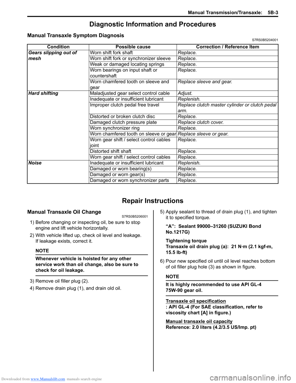
Manual Transaxle Oil ChangeS7RS0B5206001
1) Before changing or inspecting oil, be sure to stop engine and lift vehicle horizontally.
2) With vehicle lifted up, check oil level and leakage. If leakage exists, correct it.
NOTE
Whenever vehicle is hoisted for any other
service work than oil change, also be sure to
check for oil leakage.
3) Remove oil filler plug (2).
4) Remove drain plug (1), and drain old oil. 5) Apply sealant to thread of drain plug (1), and tighten
it to specified torque.
“A”: Sealant 99000–31260 (SUZUKI Bond
No.1217G)
Tightening torque
Transaxle oil drain plug (a): 21 N·m (2.1 kgf-m,
15.5 lb-ft)
6) Pour new specified oil unt il oil level reaches bottom
of oil filler plug hole (3) as shown in figure.NOTE
It is highly recommended to use API GL-4
75W-90 gear oil.
Transaxle oil specification
: API GL-4 (For SAE classification, refer to
viscosity chart [A] in figure.)
Manual transaxle oil capacity
Reference: 2.0 liters (4.2/3.5 US/Imp. pt)
Condition Possible cause Correction / Reference Item
Gears slipping out of
mesh Worn shift fork shaft
Replace.
Worn shift fork or synchronizer sleeve Replace.
Weak or damaged locating springs Replace.
Worn bearings on input shaft or
countershaft Replace.
Worn chamfered tooth on sleeve and
gear Replace sleeve and gear.
Hard shifting Maladjusted gear select control cable Adjust.
Inadequate or insufficient lubricant Replenish.
Improper clutch pedal free travel Replace clutch master cylinder or clutch pedal
arm.
Distorted or broken clutch disc Replace.
Damaged clutch pressure plate Replace clutch cover.
Worn synchronizer ring Replace.
Worn chamfered tooth on sleeve or gear Replace sleeve or gear.
Worn gear shift / select control cables
joint Replace.
Distorted shift shaft Replace.
Worn gear shift / select control cables Replace.
Noise Inadequate or insufficient lubricant Replenish.
Damaged or worn bearing(s) Replace.
Damaged or worn gear(s) Replace.
Damaged or worn synchronizer parts Replace.