Range sensor SUZUKI SWIFT 2006 2.G Service Owners Manual
[x] Cancel search | Manufacturer: SUZUKI, Model Year: 2006, Model line: SWIFT, Model: SUZUKI SWIFT 2006 2.GPages: 1496, PDF Size: 34.44 MB
Page 1008 of 1496
Downloaded from www.Manualslib.com manuals search engine 7B-60 Air Conditioning System: Automatic Type
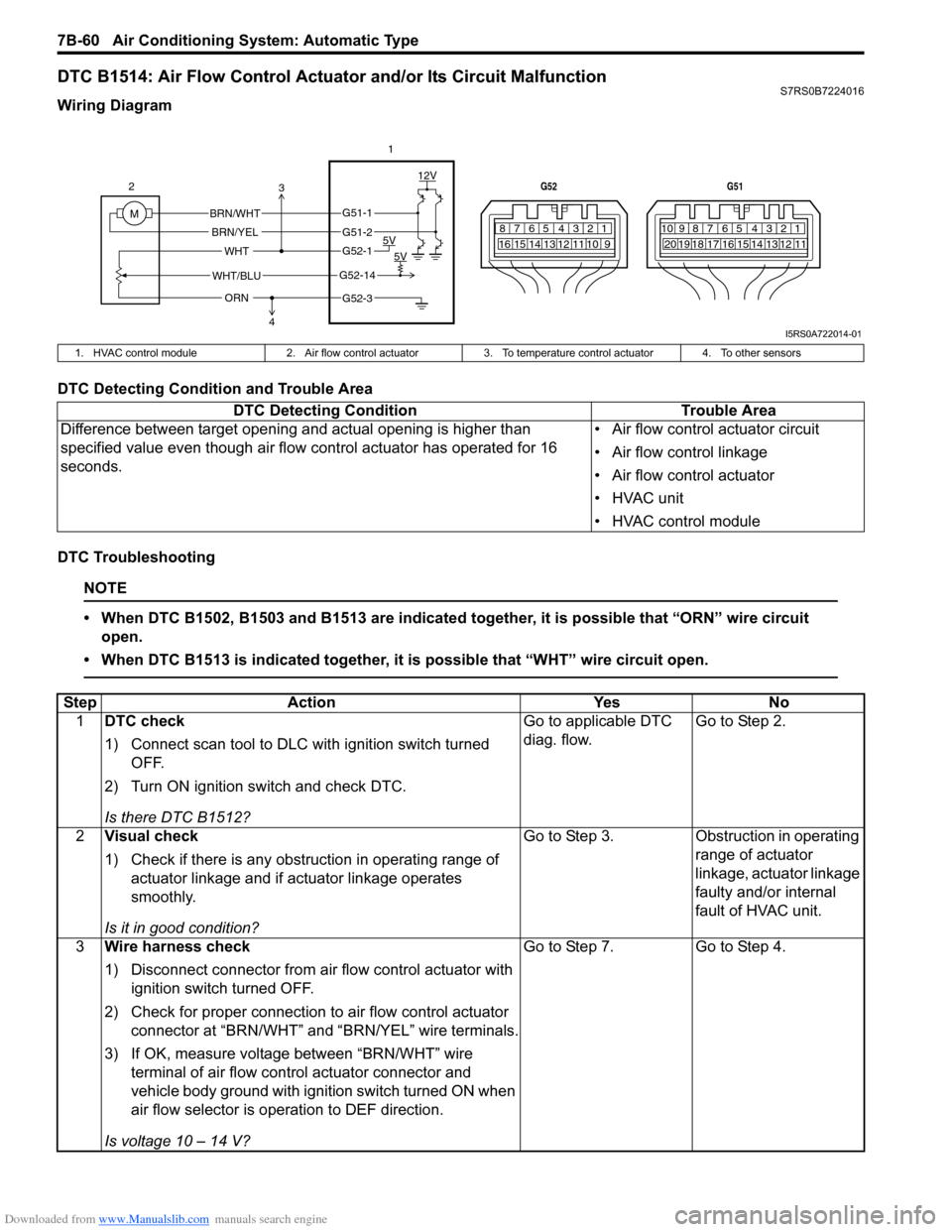
DTC B1514: Air Flow Control Actuator and/or Its Circuit MalfunctionS7RS0B7224016
Wiring Diagram
DTC Detecting Condition and Trouble Area
DTC Troubleshooting
NOTE
• When DTC B1502, B1503 and B1513 are indicated together, it is possible that “ORN” wire circuit open.
• When DTC B1513 is indicated together, it is possible that “WHT” wire circuit open.
7812910
65 431516 14 13 12 11
G52
789101920121112
65 431718 16 15 14 13
G51
M 12V
5V 5V
WHT/BLU
WHT
BRN/WHT
BRN/YEL
2
1
ORN
G51-1
G51-2
G52-1
G52-14
G52-3
3
4
I5RS0A722014-01
1. HVAC control module 2. Air flow control actuator3. To temperature control actuator 4. To other sensors
DTC Detecting Condition Trouble Area
Difference between target opening and actual opening is higher than
specified value even though air flow control actuator has operated for 16
seconds. • Air flow control actuator circuit
• Air flow control linkage
• Air flow control actuator
• HVAC unit
• HVAC control module
Step
Action YesNo
1 DTC check
1) Connect scan tool to DLC with ignition switch turned
OFF.
2) Turn ON ignition switch and check DTC.
Is there DTC B1512? Go to applicable DTC
diag. flow.
Go to Step 2.
2 Visual check
1) Check if there is any obstruction in operating range of
actuator linkage and if actuator linkage operates
smoothly.
Is it in good condition? Go to Step 3.
Obstruction in operating
range of actuator
linkage, actuator linkage
faulty and/or internal
fault of HVAC unit.
3 Wire harness check
1) Disconnect connector from air flow control actuator with
ignition switch turned OFF.
2) Check for proper connection to air flow control actuator
connector at “BRN/WHT” and “BRN/YEL” wire terminals.
3) If OK, measure voltage between “BRN/WHT” wire terminal of air flow control actuator connector and
vehicle body ground with ignition switch turned ON when
air flow selector is operation to DEF direction.
Is voltage 10 – 14 V? Go to Step 7.
Go to Step 4.
Page 1019 of 1496
Downloaded from www.Manualslib.com manuals search engine Air Conditioning System: Automatic Type 7B-71
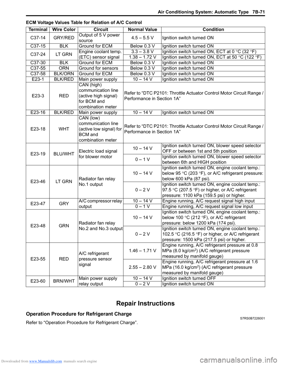
ECM Voltage Values Table for Relation of A/C Control
Repair Instructions
Operation Procedure for Refrigerant ChargeS7RS0B7226001
Refer to “Operation Procedure for Refrigerant Charge”.Terminal Wire Color Circuit Normal Value Condition
C37-14 GRY/RED Output of 5 V power
source 4.5 – 5.5 V Ignition switch turned ON
C37-15 BLK Ground for ECM Below 0.3 V Ignition switch turned ON
C37-24 LT GRN Engine coolant temp.
(ETC) sensor signal 3.3 – 3.8 V Ignition switch turned ON, ECT at 0
°C (32 ° F)
1.38 – 1.72 V Ignition switch turned ON, ECT at 50 °C (122 °F)
C37-30 BLK Ground for ECM Below 0.3 V Ignition switch turned ON
C37-55 ORN Ground for sensors Below 0.3 V Ignition switch turned ON
C37-58 BLK/ORN Ground for ECM Below 0.3 V Ignition switch turned ON E23-1 BLK/RED Main power supply 10 – 14 V Ignition switch turned ON
E23-3 RED CAN (high)
communication line
(active high signal)
for BCM and
combination meterRefer to “DTC P2101: Throttle Actu
ator Control Motor Circuit Range /
Performance in Section 1A”
E23-16 BLK/RED Main power supply 10 – 14 V Ignition switch turned ON
E23-18 WHT CAN (low)
communication line
(active low signal) for
BCM and
combination meterRefer to “DTC P2101: Throttle Actu
ator Control Motor Circuit Range /
Performance in Section 1A”
E23-19 BLU/WHT Electric load signal
for blower motor 10 – 14 V
Ignition switch turned ON, blower speed selector
OFF or between 1st and 5th position
0 – 1 V Ignition switch turned ON, blower speed selector
between 6th and HIGH position
E23-46 LT GRN Radiator fan relay
No.1 output 10 – 14 V
Ignition switch turned ON, engine coolant temp.:
below 95
°C (203 ° F), or A/C refrigerant pressure:
below 600 kPa (87 psi).
0 – 2 V Ignition switch turned ON, engine coolant temp.:
97.5
°C (207.5 °F) or higher, or A/C refrigerant
pressure: 1100 kPa (159.5 psi) or higher.
E23-47 GRY A/C compressor relay
output 10 – 14 V Engine running, A/C request signal high input
0 – 1 V Engine running, A/C request signal low input
E23-48 GRN Radiator fan relay
No.2 and No.3 output 10 – 14 V
Ignition switch turned ON, engine coolant temp.:
below 100
°C (212 °F), or A/C refrigerant
pressure: below 1200 kPa (174 psi).
0 – 2 V Ignition switch turned ON, engine coolant temp.:
102.5
°C (216.5 ° F) or higher, or A/C refrigerant
pressure: 1500 kPa (217.5 psi) or higher.
E23-55 RED A/C refrigerant
pressure sensor
signal 1.46 – 1.71 V
Engine running, A/C refrigerant pressure at 0.8
MPa (8.0 kg/cm
2) (A/C refrigerant pressure
measured by manifold gauge)
2.55 – 2.80 V Engine running, A/C refrigerant pressure at 1.6
MPa (16.0 kg/cm
2) (A/C refrigerant pressure
measured by manifold gauge)
E23-60 BRN/WHT Main power supply
relay output 10 – 14 V Ignition switch turned OFF
0 – 2 V Ignition switch turned ON
Page 1046 of 1496
Downloaded from www.Manualslib.com manuals search engine 8B-8 Air Bag System:
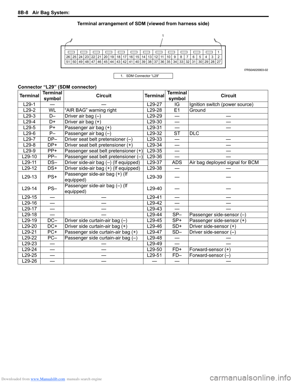
Terminal arrangement of SDM (viewed from harness side)
Connector “L29” (SDM connector)
1 2345678910
11
1213141516171819202122232425
272829303132333435363738394041424344454647484950
1
26
51
I7RS0A820003-02
1. SDM Connector “L29”
Terminal Terminal
symbol Circuit Terminal Terminal
symbol Circuit
L29-1 — — L29-27 IG Ignition switch (power source)
L29-2 WL “AIR BAG” warning right L29-28 E1 Ground
L29-3 D– Driver air bag (–) L29-29 — —
L29-4 D+ Driver air bag (+) L29-30 — —
L29-5 P+ Passenger air bag (+) L29-31 — —
L29-6 P– Passenger air bag (–) L29-32 ST DLC
L29-7 DP– Driver seat belt pretensioner (–) L29-33 — —
L29-8 DP+ Driver seat belt pretensioner (+) L29-34 — —
L29-9 PP+ Passenger seat belt pretensioner (+) L29-35 — —
L29-10 PP– Passenger seat belt pretensioner (–) L29-36 — — L29-11 DS– Driver side-air bag (–) (If equipped ) L29-37 ADS Air bag deployed signal for BCM
L29-12 DS+ Driver side-air bag (+) (If equipped) L29-38 — —
L29-13 PS+ Passenger side-air bag (+) (If
equipped) L29-39 — —
L29-14 PS– Passenger side-air bag (–) (If
equipped) L29-40 — —
L29-15 — — L29-41 — —
L29-16 — — L29-42 — —
L29-17 — — L29-43 — —
L29-18 — — L29-44 SP– Passenger side-sensor (–)
L29-19 DC– Driver side curtain-air bag (–) L29-45 SP+ Passenger side-sensor (+)
L29-20 DC+ Driver side curtain-air bag (+) L29-46 SD+ Driver side-sensor (+)
L29-21 PC+ Passenger side curtain-air bag (+) L29-47 SD– Driver side-sensor (–)
L29-22 PC– Passenger side curtain-air bag (–) L29-48 — —
L29-23 — — L29-49 — —
L29-24 — — L29-50 FD+ Forward-sensor (+)
L29-25 — — L29-51 FD– Forward-sensor (–)
L29-26 — — — — —
Page 1182 of 1496

Downloaded from www.Manualslib.com manuals search engine 9A-11 Wiring Systems:
C: Engine harnessNo./Color Connective position No./Color Connective positionC01/GRY IAC valve C22/- Generator #2
C02/GRY IG Coil #1 C23/BLK Starting motor #1
C03/GRY IG Coil #2 C24/- Starting motor #2
C04/GRY Fuel injector #1 C25/GR Y VSS (Vehicle speed sensor)
C05/GRY Fuel injector #2 C26/GRY Knock sensor
C06/GRY Fuel injector #3 C27/BLU (A/
T) Input shaft speed sensor
C07/GRY Fuel injector #4 C28/GRY
(A/T) Trans axle range sensor
C08/BLK or GRY CMP sensor C29/GRY
(A/T) Shift solenoid
C09/BLK ECT sensor C30/BLK
(M/T) Back-up light switch
C10/GRY EGR stepper motor C31/- Main fuse box C11/BLK Throttle position sensor C32/GRY
(IF EQPD) Current sensor
C12/BLK MAP sensor C33/- Main fuse box
C13/BLK MAF sensor C34/N (A/T) TCM
C14/BLK EVAP canister purge valve C35/N (A/T) TCM
C15/GRY Heated oxygen sensor #1 C36/N Main harness (To E24)
C16/GRN Heated oxygen sensor #2 C37/GRY ECM C17/BLK A/C compressor C38/- Weld splice C18/N Oil pressure switch C39/- Weld splice
C19/BLU VVT solenoid C40/- Weld splice
C20/GRY CKP sensor C41/- Weld splice
C21/GRY or BLK Generator #1
Page 1184 of 1496

Downloaded from www.Manualslib.com manuals search engine 9A-13 Wiring Systems:
C: Engine harness
D: Oil pressure switch wireNo./Color Connective position No./Color Connective position
C02/GRY IG Coil #1 C24/- Starting motor #2
C03/GRY IG Coil #2 C23/BLK Starting motor #1
C04/GRY Fuel injector #1 C25/GRY
(A/T) VSS (Vehicle speed sensor)
C05/GRY Fuel injector #2 C26/GRY Knock shaft speed sensor
C06/GRY Fuel injector #3 C27/BLU (A/
T) Input shaft speed sensor
C07/GRY Fuel injector #4 C28/GRY
(A/T) Trans axle range sensor
C08/BLK CMP sensor C29/GRY
(A/T) Shift solenoid
C09/BLK ECT sensor C30/BLK
(M/T) Back-up light switch
C10/GRY EGR stepper motor C31/- Main fuse box C12/BLK MAP sensor C32/GRY Current sensor
C13/BLK MAF sensor C33/- Main fuse box
C14/BLK EVAP canister purge valve C34/N (A/T) TCM
C15/BLK Heated oxygen sensor #1 C35/N (A/T) TCM
C16/GRN Heated oxygen sensor #2 C36/N Main harness (To E24) C17/BLK A/C compressor C37/GRY ECM C18/N Oil pressure switch wire (To D02) C38/- Weld splice
C19/BLU VVT solenoid C39/- Weld splice
C20/GRY CKP sensor C40/- Weld splice C21/BLK Generator #1 C42/BLK Electric throttle body C22/- Generator #2
No./Color Connective position No./ColorConnective position
D01/N Oil pressure switch D02/GRY Engine harness (To C18)
Page 1206 of 1496
Downloaded from www.Manualslib.com manuals search engine 9A-35 Wiring Systems:
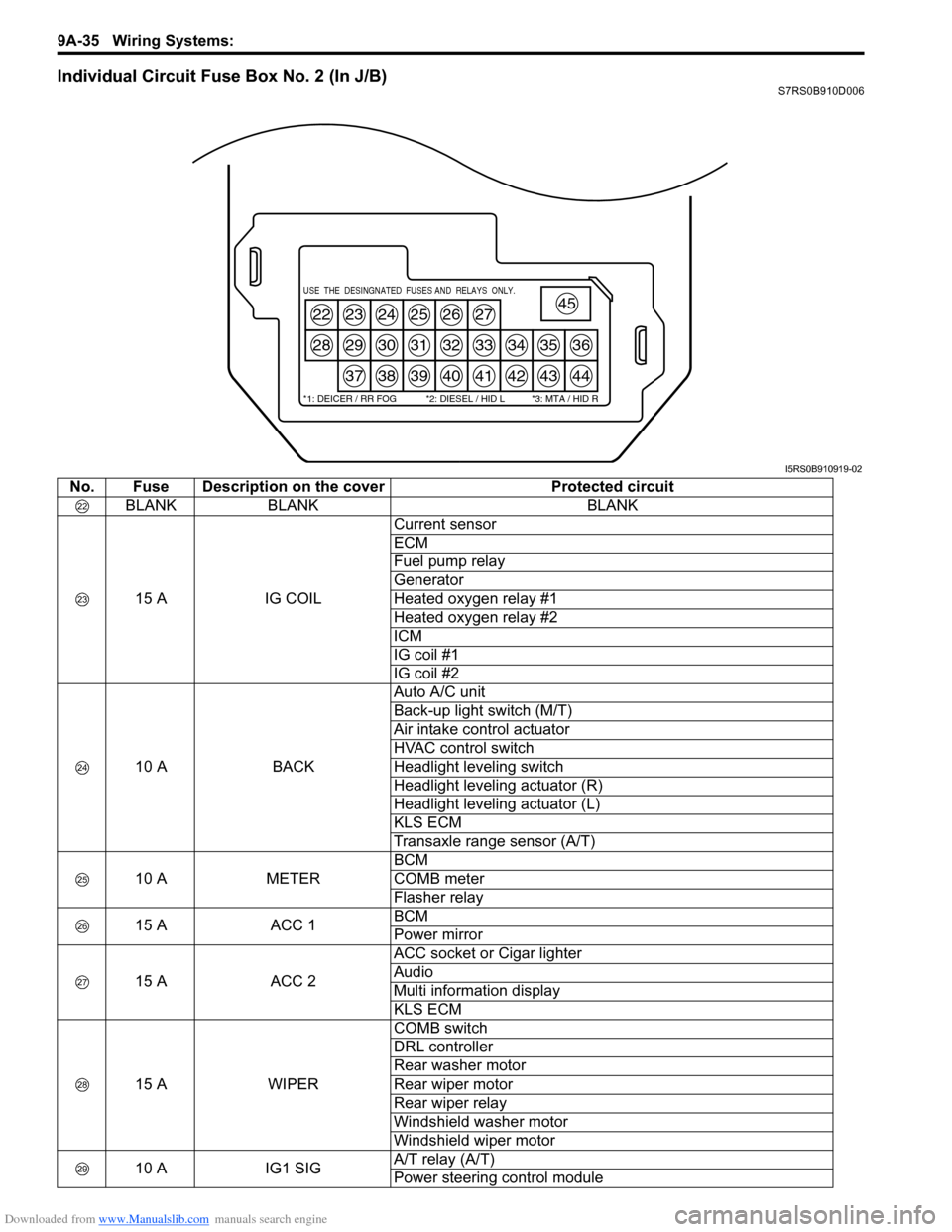
Individual Circuit Fuse Box No. 2 (In J/B)S7RS0B910D006
22
28
23
29
37
24
30
38
25
31
39
26
32
40
27
33
41
34
42
35
43
36
44
45USE THE DESINGNATED FUSES AND RELAYS ONLY.
*1: DEICER / RR FOG *2: DIESEL / HID L *3: MTA / HID R
I5RS0B910919-02
No. Fuse Description on the coverProtected circuit
BLANK BLANK BLANK
15 A IG COILCurrent sensor
ECM
Fuel pump relay
Generator
Heated oxygen relay #1
Heated oxygen relay #2
ICM
IG coil #1
IG coil #2
10 A BACKAuto A/C unit
Back-up light switch (M/T)
Air intake control actuator
HVAC control switch
Headlight leveling switch
Headlight leveling actuator (R)
Headlight leveling actuator (L)
KLS ECM
Transaxle range sensor (A/T)
10 A METERBCM
COMB meter
Flasher relay
15 A ACC 1BCM
Power mirror
15 A ACC 2ACC socket or Cigar lighter
Audio
Multi information display
KLS ECM
15 A WIPERCOMB switch
DRL controller
Rear washer motor
Rear wiper motor
Rear wiper relay
Windshield washer motor
Windshield wiper motor
10 A IG1 SIGA/T relay (A/T)
Power steering control module
Page 1217 of 1496
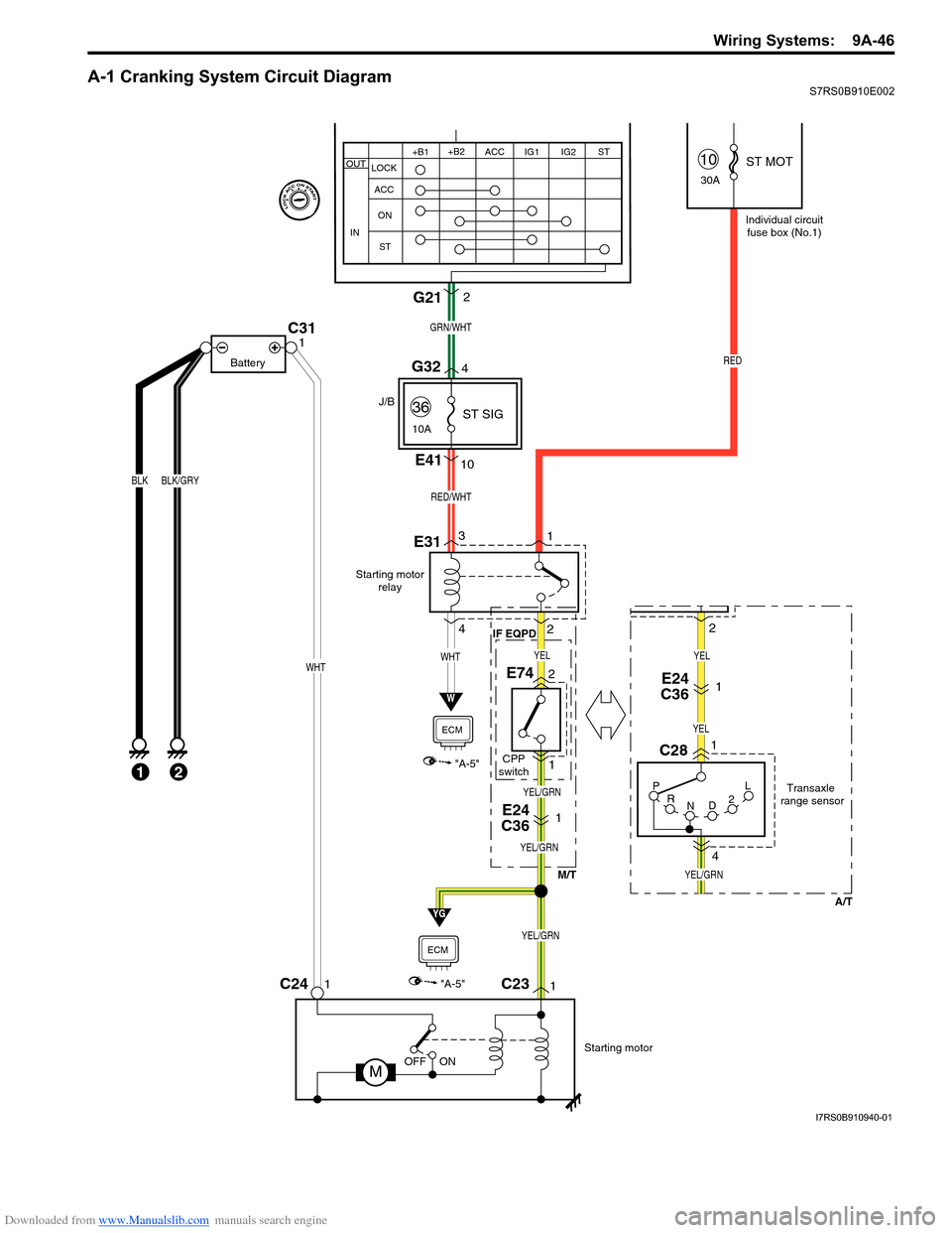
Downloaded from www.Manualslib.com manuals search engine Wiring Systems: 9A-46
A-1 Cranking System Circuit DiagramS7RS0B910E002
Starting motorrelay
W
"A-5"
ECM
P
R N D2LTransaxle
range sensor
C28
E741
4
E31
C231C241
Starting motor
MOFF ON
BLK
1
BLK/GRY
C311
Battery
E24
C361
RED
Individual circuit
fuse box (No.1)
10
30A
36
10A
WHTWHT
M/T
IF EQPD
E24
C361
J/B
A/T
E4110
13
2
4
RED/WHT
2 ST MOT
ST SIG
YEL/GRN
YG
"A-5"
ECM
GRN/WHT
G212
YEL/GRN
YEL/GRN
YEL
YEL/GRN
YEL
YEL
G324
+B1
LOCK
ACC
ON
ST ACC IG1 IG2
STOUT
IN
+B2
21CPP
switch
2
I7RS0B910940-01
Page 1224 of 1496
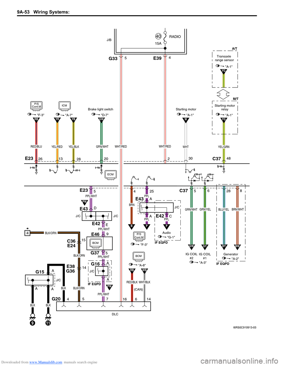
Downloaded from www.Manualslib.com manuals search engine 9A-53 Wiring Systems:
J/C
E43
J/C
G16
DLC
G20
G375
E469
E38
G3614
C36 E2415
BLK/ORN
BLK/ORN
BLK/ORN
4
BLK
11
J/C
G15
5
4
516
WHT/RED
C37
GRN/YELGRN/WHT
5 6
YG
BRN
B
P/S
Cont.M
4
"F-3"
25
A
A D
E
AA
PPL/WHT
PPL/WHT
PPL/WHT
PPL/WHT
YEL/GRNWHT/RED
BLK
9
A
PPL
E42
PPLJ/C
ECM
E394
J/B15A RADIO
40
E23
E23
YEL/BLKYEL/REDRED/BLU
13
282620
BLK
2C37
M/T
A/T
48
W
WHT
30
GYGW
BRN/WHTBLU/YEL
28
8
BWBY
IG COIL
#1 Generator
IG COIL
#2
(CAN) "A-3""A-2"
Audio
"G-1"
GRN/WHT
P
7
BCM
Starting motor relay
"A-1"
Transaxle
range sensor
YG"A-1"
ICM
"A-7"
P/S
Cont.M
"F-3"YBYRRBGW"D-7"
Brake light switch
"A-1"Starting motor
PW
PW
G335
WHT/BLKRED/BLK
RBWB
"A-8"
14
6
BCM
A
J/C
E43
APPL
P
E42C
IF EQPD IF EQPD
IF EQPD
I6RS0C910913-03
Page 1226 of 1496
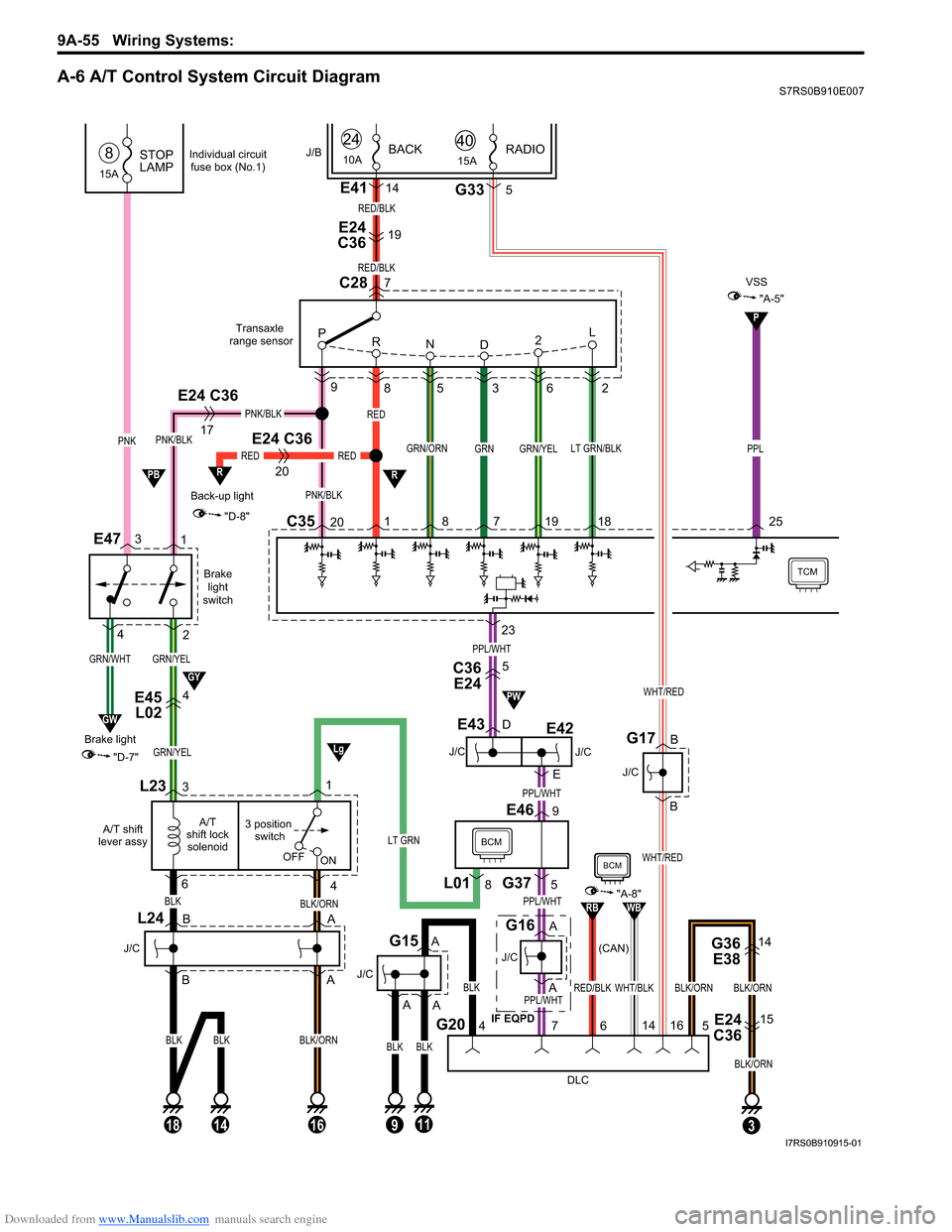
Downloaded from www.Manualslib.com manuals search engine 9A-55 Wiring Systems:
A-6 A/T Control System Circuit DiagramS7RS0B910E007
GRN/YEL
Brakelight
switch
E47
GRN/YEL
C3520 8 7 19 18
9
85 3 6 2
GRN/YEL
Back-up light
20
RED
"D-8"
R
Transaxle
range sensor
TCM
L23
4
3 position switch
A/T
shift lock solenoid
A/T shift
lever assy
BLK/ORN
16
OFF ON
RED
1
RED
BLK
PNK/BLK
GRN/ORNLT GRN/BLK
C28
P
R ND 2L
PNK/BLK
1
2
E24 C36
17
PNK/BLK
BLK
63
BLK/ORN
18
BLK
14
L24
J/C
E45
L024
J/C
E43
J/C (CAN)
G16
BCM
DLC
G207
G375
E469
4
BLK
BLKBLK
11
J/C
G15
3
G36
E3814
E24
C3615
BLK/ORNBLK/ORN
5
23
GRN
RED/BLK
7
E24
C3619
E4114
RED/BLK
PNK
15A
STOP
LAMP8
GRN/WHT
GW
"D-7"
Brake light
3
4
J/B
L018
1
24
10ABACK
A
A
B
B A
A
PPL/WHT
PPL/WHT
PPL/WHT
PPL/WHT
A
A
D
E
LT GRN
P
"A-5"
VSS
PPL
25
R
C36E245
Lg
GY
PB
PW
9
A
Individual circuit
fuse box (No.1)
WHT/BLKRED/BLK
RBWB
BCM
"A-8"
14
6
BLK/ORN
15ARADIO40
G335
WHT/RED
B
B
J/C
G17
WHT/RED
16
J/C
E42
IF EQPD
E24 C36
I7RS0B910915-01
Page 1257 of 1496
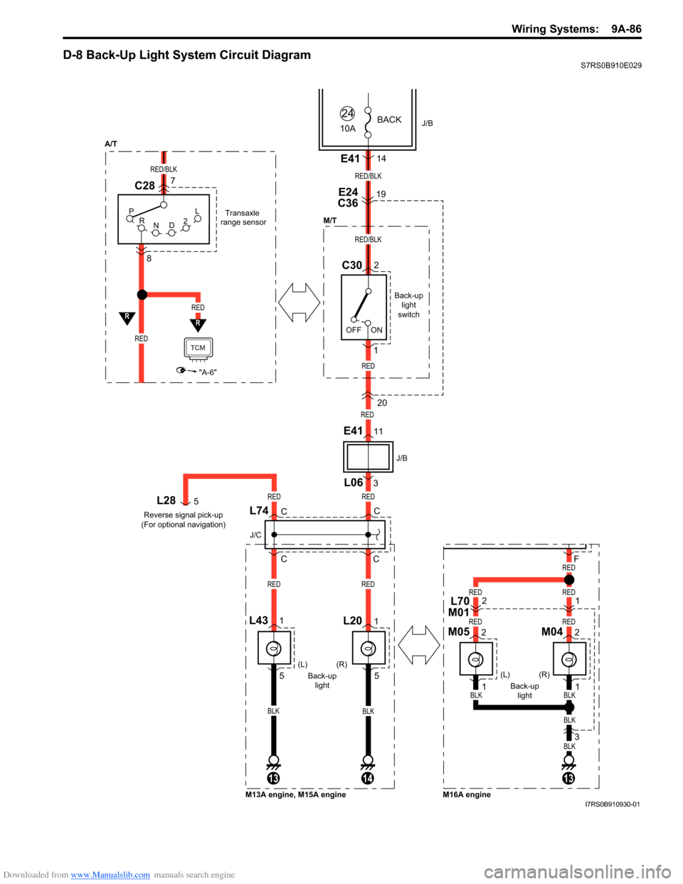
Downloaded from www.Manualslib.com manuals search engine Wiring Systems: 9A-86
D-8 Back-Up Light System Circuit DiagramS7RS0B910E029
BLKBLK
141313
CC
C
J/C
L74CL28
Back-up light
switch
Back-up light (R)
RED
RED
RED/BLK
RED/BLK
ON
OFF J/B
10A
24BACK
E24
C3619
C302
1 20
L431L201
RED
RED
RED
M/T
L063
E4111
J/B
P R N D2LTransaxle
range sensor
RED/BLK
C28
R
RED
8
RED
"A-6"
TCM
R
E4114
7
5 5
Reverse signal pick-up
(For optional navigation)
5RED
(L)
Back-uplight (R)
(L)
M13A engine, M15A engine M16A engine
BLK
BLK
BLKBLK
F
M042
RED
REDRED
REDRED
1
M052
1
1L70
M012
3
A/T
I7RS0B910930-01