motor SUZUKI SWIFT 2006 2.G Service Owners Manual
[x] Cancel search | Manufacturer: SUZUKI, Model Year: 2006, Model line: SWIFT, Model: SUZUKI SWIFT 2006 2.GPages: 1496, PDF Size: 34.44 MB
Page 630 of 1496
Downloaded from www.Manualslib.com manuals search engine 4F-56 Electronic Stability Program:
ESP® Hydraulic Unit / Control Module Assembly Removal and InstallationS7RS0B4606037
CAUTION!
Never disassemble ESP ® hydraulic unit / control module assembly loosen blind plug or remove motor.
Performing any of these proh ibited services will affect original performance of ESP ® hydraulic unit /
control module assembly.
Removal
CAUTION!
• Do not give an impact to hydraulic unit.
• Use care not to allow dust to enter hydraulic unit.
• Do not place hydraulic unit on its side or upside down. Handling it in inappropriate
way will affect its original performance.
1) Disconnect negative (–) cable from battery.
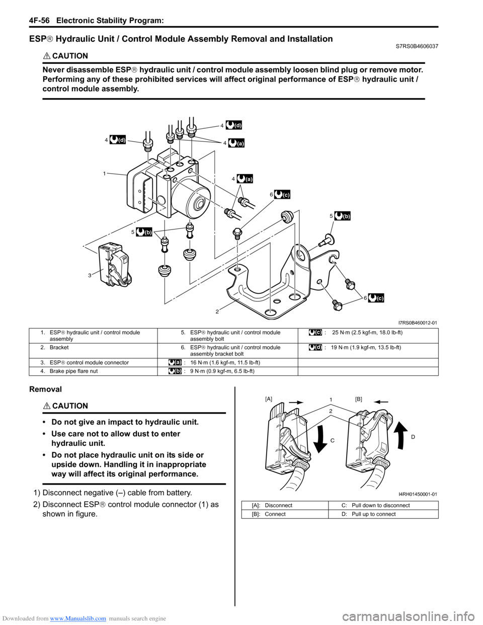
2) Disconnect ESP ® control module connector (1) as
shown in figure.
3 1
(c)
2
(b)
(a)4
(a)
4
5
6
(b)
5
(c)
6
(d)
(d) 4
4
I7RS0B460012-01
1. ESP ® hydraulic unit / control module
assembly 5. ESP
® hydraulic unit / control module
assembly bolt : 25 N
⋅m (2.5 kgf-m, 18.0 lb-ft)
2. Bracket 6. ESP ® hydraulic unit / control module
assembly bracket bolt : 19 N
⋅m (1.9 kgf-m, 13.5 lb-ft)
3. ESP ® control module connector : 16 N ⋅m (1.6 kgf-m, 11.5 lb-ft)
4. Brake pipe flare nut : 9 N ⋅m (0.9 kgf-m, 6.5 lb-ft)
[A]: DisconnectC: Pull down to disconnect
[B]: Connect D: Pull up to connect
21
C D
[A]
[B]
I4RH01450001-01
Page 654 of 1496
Downloaded from www.Manualslib.com manuals search engine 5A-10 Automatic Transmission/Transaxle:
Schematic and Routing Diagram
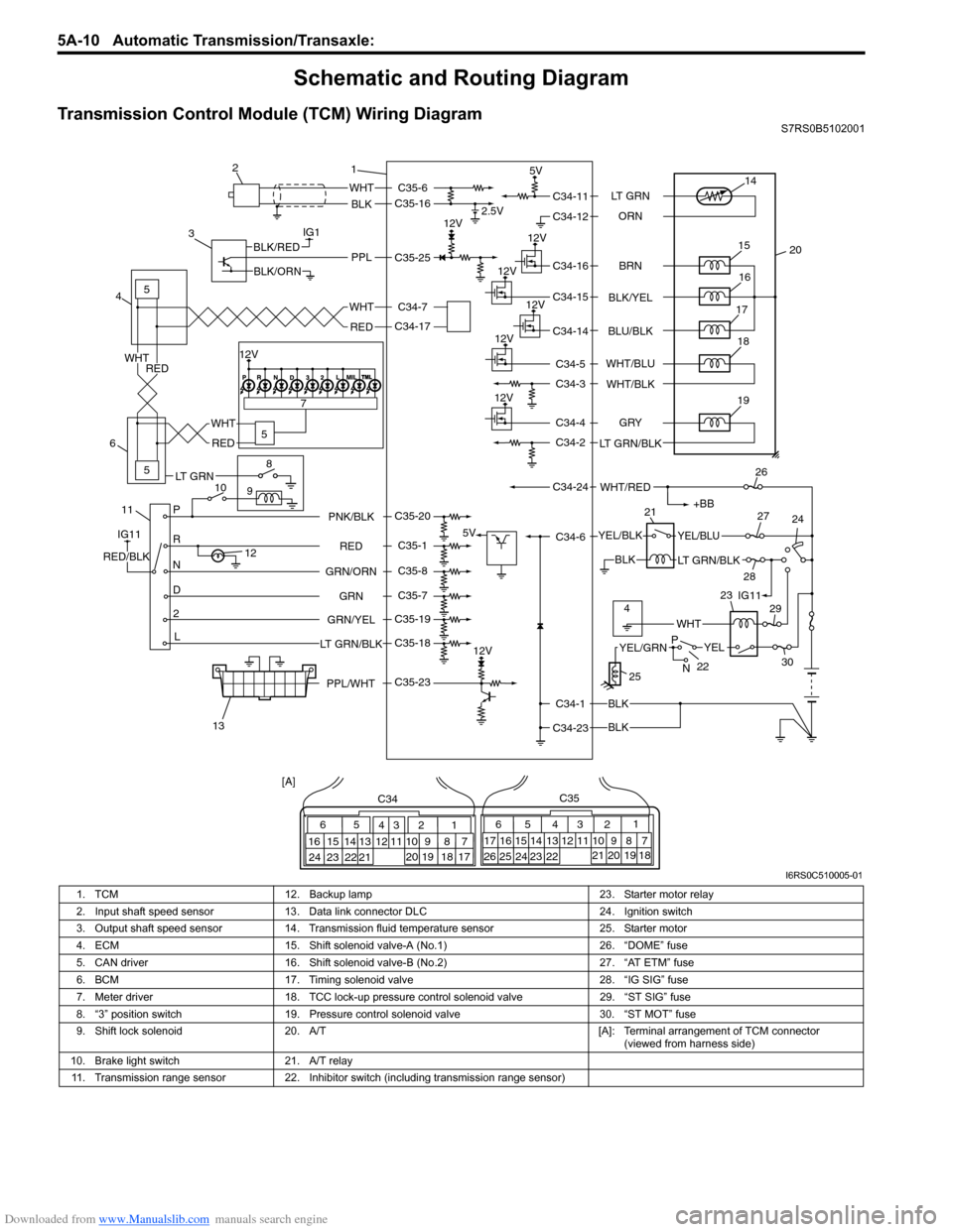
Transmission Control Module (TCM) Wiring DiagramS7RS0B5102001
IG1
115
5
5
8
9
10 7
P
R
N
D
2
L
12
12V 2.5V
5V
12V
5V
12V
12V
12V
12V
WHT
BLK
BLK
BLK
BLK
PPLBLK/RED
BLK/ORN
IG11
RED/BLK
YEL/BLKYEL/BLU
LT GRN/BLK
+BB
WHT/RED
14
20
15
16
17
19
12V18
1
2
3
4
6
13 21
26
24
27
28 29
30
WHT
WHT
RED
RED
WHT
RED
65
16 15 14 13 12 11 43
24 23 2122 10 9 8 721
1920 18 17
C34
17 16
26 25
15 14
65 3
42
13 12
23 2224 11 10 9
21 20 19 87
18
1
C35
[A]
22
25
YELYEL/GRN
WHT
P
N
BRN
LT GRN
ORN
BLK/YEL
BLU/BLK
GRY
LT GRN/BLK WHT/BLU
WHT/BLK
C34-11
C34-12
C34-16
C34-15
C34-14
C34-4
C34-2
C34-1
C34-23 C34-6
C34-24 C34-5
C34-3
RED
GRN
GRN/ORN PNK/BLK
GRN/YEL
LT GRN/BLKC35-6
C35-16
C35-23 C35-25
C35-20
C35-1
C35-8
C35-7
C35-19
C35-18 C34-17 C34-7
4IG11
12V
23
PPL/WHT
LT GRN
I6RS0C510005-01
1. TCM 12. Backup lamp 23. Starter motor relay
2. Input shaft speed sensor 13. Data link connector DLC 24. Ignition switch
3. Output shaft speed sensor 14. Transmission fluid temperature sensor 25. Starter motor
4. ECM 15. Shift solenoid valve-A (No.1) 26. “DOME” fuse
5. CAN driver 16. Shift solenoid valve-B (No.2) 27. “AT ETM” fuse
6. BCM 17. Timing solenoid valve 28. “IG SIG” fuse
7. Meter driver 18. TCC lock-up pressure control solenoid valve 29. “ST SIG” fuse
8. “3” position switch 19. Pressure control solenoid valve 30. “ST MOT” fuse
9. Shift lock solenoid 20. A/T [A]: Terminal arrangement of TCM connector
(viewed from harness side)
10. Brake light switch 21. A/T relay
11. Transmission range sensor 22. Inhibitor switch (including transmission range sensor)
Page 750 of 1496
Downloaded from www.Manualslib.com manuals search engine 5A-106 Automatic Transmission/Transaxle:
Automatic Transaxle Unit Dismounting and
Remounting
S7RS0B5106031
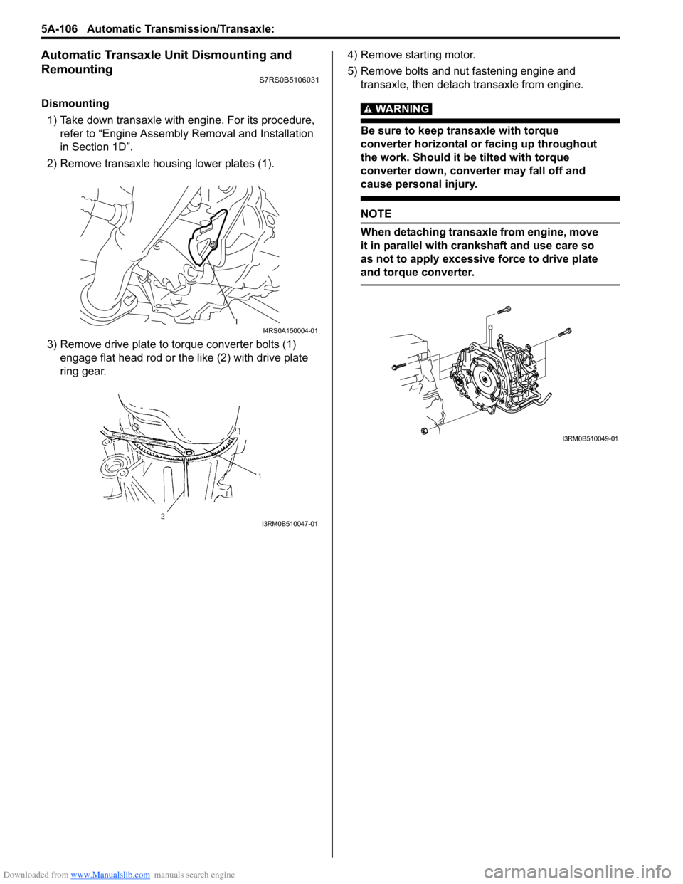
Dismounting1) Take down transaxle with engine. For its procedure, refer to “Engine Assembly Removal and Installation
in Section 1D”.
2) Remove transaxle housing lower plates (1).
3) Remove drive plate to torque converter bolts (1) engage flat head rod or the like (2) with drive plate
ring gear. 4) Remove starting motor.
5) Remove bolts and nut fastening engine and
transaxle, then detach transaxle from engine.WARNING!
Be sure to keep transaxle with torque
converter horizontal or facing up throughout
the work. Should it be tilted with torque
converter down, converter may fall off and
cause personal injury.
NOTE
When detaching transaxle from engine, move
it in parallel with cranks haft and use care so
as not to apply excessive force to drive plate
and torque converter.
1I4RS0A150004-01
I3RM0B510047-01
I3RM0B510049-01
Page 751 of 1496
Downloaded from www.Manualslib.com manuals search engine Automatic Transmission/Transaxle: 5A-107
Remounting1) Make sure that torque converter is installed correctly to transaxle.
Refer to “Automatic Transaxle Unit Assembly”.
2) Attach transaxle to engine.
WARNING!
Be sure to keep transaxle with torque
converter horizontal or facing up throughout
the work. Should it be tilted with torque
converter down, converter may fall off and
cause personal injury.
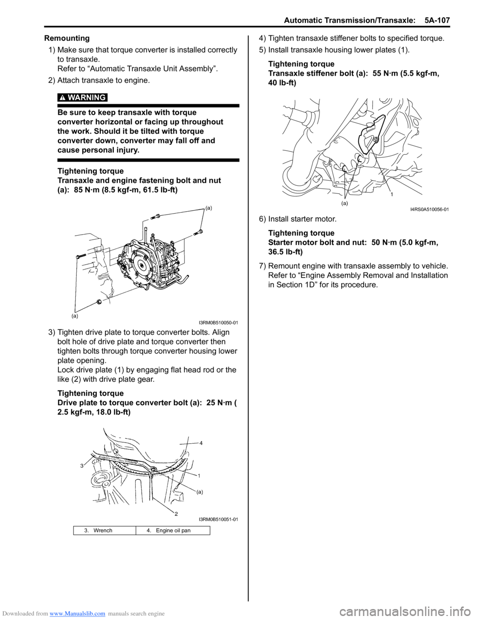
Tightening torque
Transaxle and engine fastening bolt and nut
(a): 85 N·m (8.5 kgf-m, 61.5 lb-ft)
3) Tighten drive plate to torque converter bolts. Align bolt hole of drive plate and torque converter then
tighten bolts through torque converter housing lower
plate opening.
Lock drive plate (1) by engaging flat head rod or the
like (2) with drive plate gear.
Tightening torque
Drive plate to torque converter bolt (a): 25 N·m (
2.5 kgf-m, 18.0 lb-ft) 4) Tighten transaxle stiffener bolts to specified torque.
5) Install transaxle housing lower plates (1).
Tightening torque
Transaxle stiffener bolt (a): 55 N·m (5.5 kgf-m,
40 lb-ft)
6) Install starter motor. Tightening torque
Starter motor bolt and nut: 50 N·m (5.0 kgf-m,
36.5 lb-ft)
7) Remount engine with transaxle assembly to vehicle. Refer to “Engine Assembly Removal and Installation
in Section 1D” for its procedure.
3. Wrench 4. Engine oil pan
I3RM0B510050-01
I3RM0B510051-01
1
(a)
I4RS0A510056-01
Page 811 of 1496

Downloaded from www.Manualslib.com manuals search engine Automatic Transmission/Transaxle: 5A-167
Specifications
Tightening Torque SpecificationsS7RS0B5107001
NOTE
The specified tightening torque is also described in the following.
“Select Cable Components”
“Automatic Transaxle Unit Components”
“Automatic Transaxle Assembly Components”
“Oil Pump Assembly Components”
“Transaxle Rear Cover (O/D and 2nd Coast Brake Piston) Assembly Components”
“Valve Body Assembly Components”
“Differential Assembly Components”
Reference:
For the tightening torque of fastener not specified in this section, refer to “Fasteners Information in Section 0A”.
Fastening part
Tightening torque
Note
N ⋅mkgf-mlb-ft
A/T fluid drain plug 171.7 12.5 �) / �) / �)
Transmission range sensor bolt 5.5 0.55 4.0�) / �)
Output shaft speed sensor bolt 131.3 9.5 �) / �)
Input shaft speed sensor bolt 5.5 0.55 4.0�)
Valve body harness connector bolt 7.00.7 5.0 �)
Shift solenoid bolt 111.1 8.0 �)
Oil strainer bolt 101.0 7.5 �) / �)
Oil pan bolt 7.00.7 5.0 �) / �)
Transaxle and engine fastening bolt and nut 85 8.5 61.5�)
Drive plate to torque converter bolt 252.5 18.0 �)
Transaxle stiffener bolt 555.5 40�)
Starter motor bolt and nut 505.0 36.5 �)
Oil pump subassembly bolt 101.0 7.5 �)
Rear cover plug 7.5 0.75 5.5�)
Solenoid valve bolt 111.1 8.0 �)
Final gear bolt 787.8 56.5 �)
Torque converter housing plug 7.5 0.75 5.5�)
Lubrication tube clamp bolt 5.5 0.55 4.0�)
Fluid reservoir RH plate bolt 5.5 0.55 4.0�)
Torque converter housing bolt 292.9 21�) / �) / �)
Manual detent spring bolt 101.0 7.5 �)
Parking lock pawl bracket bolt 7.5 0.75 5.5�)
Rear cover bolt 252.5 18.0 �)
Fluid reservoir LH plate bolt 101.0 7.5 �)
Oil pump assembly bolt 252.5 18.0 �)
Transaxle case plug 7.5 0.75 5.5�)
Valve body harness connector bolt 5.5 0.55 4.0�)
Valve body bolt 111.1 8.0 �)
Fluid outlet union 252.5 18.0 �)
Fluid cooler pipe union bolt 222.2 16.0 �)
Fluid cooler pipe bracket bolt 101.0 7.5 �)
Fluid filler tube bolt 101.0 7.5 �)
Input shaft speed sensor bolt 111.1 8.0 �)
Harness bracket bolt 232.3 17.0 �)
Select cable clamp bolt 101.0 7.5 �)
Transmission range sensor lock nut 70.7 5.0 �)
Manual select lever nut 131.3 9.5 �)
Engine mounting LH bracket bolt 555.5 40.0
�)
Page 823 of 1496
Downloaded from www.Manualslib.com manuals search engine Manual Transmission/Transaxle: 5B-9
Manual Transaxle Unit Dismounting and
Remounting
S7RS0B5206009
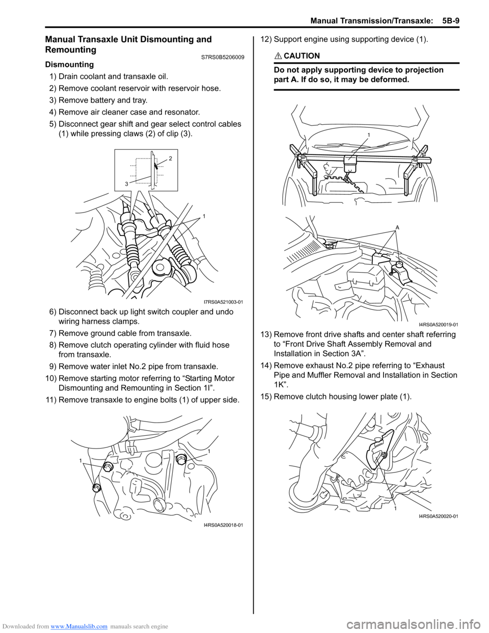
Dismounting1) Drain coolant and transaxle oil.
2) Remove coolant reservoir with reservoir hose.
3) Remove battery and tray.
4) Remove air cleaner case and resonator.
5) Disconnect gear shift and gear select control cables (1) while pressing claws (2) of clip (3).
6) Disconnect back up light switch coupler and undo wiring harness clamps.
7) Remove ground cable from transaxle.
8) Remove clutch operating cylinder with fluid hose from transaxle.
9) Remove water inlet No.2 pipe from transaxle.
10) Remove starting motor re ferring to “Starting Motor
Dismounting and Remounting in Section 1I”.
11) Remove transaxle to engine bolts (1) of upper side. 12) Support engine using supporting device (1).
CAUTION!
Do not apply supporting device to projection
part A. If do so, it may be deformed.
13) Remove front drive shafts and center shaft referring
to “Front Drive Shaft Assembly Removal and
Installation in Section 3A”.
14) Remove exhaust No.2 pipe referring to “Exhaust Pipe and Muffler Removal a nd Installation in Section
1K”.
15) Remove clutch housing lower plate (1).
1
2
3
I7RS0A521003-01
1
1
I4RS0A520018-01
1
A
I4RS0A520019-01
1I4RS0A520020-01
Page 867 of 1496

Downloaded from www.Manualslib.com manuals search engine Table of Contents 6- i
6
Section 6
CONTENTS
Steering
Precautions ................................................. 6-1
Precautions............................................................. 6-1
Precautions on Steering........................................ 6-1
Steering General Diagnosi s.................... 6A-1
Precautions........................................................... 6A-1
Precautions for Steering Diagnosis ..................... 6A-1
Diagnostic Information and Procedures ............ 6A-2 Steering Symptom Diagnosis .............................. 6A-2
Steering Wheel and Column ................... 6B-1
Precautions........................................................... 6B-1
Service Precautions of Steering Wheel and Column.............................................................. 6B-1
General Description ............................................. 6B-1 Steering Wheel and Column Construction .......... 6B-1
Diagnostic Information and Procedures ............ 6B-2 Checking Steering Column for Accident Damage ............................................................ 6B-2
Repair Instructions .............................................. 6B-3 Steering Wheel and Column Construction .......... 6B-3
Steering Wheel Removal and Installation ........... 6B-4
Contact Coil Cable Assembly Removal and Installation ......................................................... 6B-5
Centering Contact Coil Cable Assembly ............. 6B-6
Contact Coil Cable Assembly Inspection ............ 6B-6
Steering Angle Sensor Removal and Installation ......................................................... 6B-6
Steering Angle Sensor Inspection ....................... 6B-6
Steering Column Removal and Installation ......... 6B-7
Steering Column Inspecti on ................................ 6B-8
Ignition Switch Cylinder Assembly Removal and Installation (Non- Keyless Start Model)...... 6B-9
Steering Lock Assembly (Ignition Switch) Removal and Installation................................... 6B-9
Steering Lower Shaft Removal and Installation ....................................................... 6B-10
Specifications ..................................................... 6B-11
Tightening Torque Specifications ...................... 6B-11
Special Tools and Equipmen t ........................... 6B-11
Special Tool ...................................................... 6B-11
Power Assisted Steering System........... 6C-1
Precautions........................................................... 6C-1 Steering System Note .........................................6C-1
Precautions in Diagnosing Troubles ...................6C-1
General Description .............................................6C-2 P/S System Description ......................................6C-2
EPS Diagnosis General Descr iption ...................6C-3
On-Board Diagnostic System Description ...........6C-3
Schematic and Routing Diagram ........................6C-4 EPS System Wiring Circuit Diagram ...................6C-4
Diagnostic Information and Procedures ............6C-5 EPS System Check .............. ...............................6C-5
“EPS” Warning Light Check . ...............................6C-8
DTC Check..........................................................6C-8
DTC Clearance ...................................................6C-9
DTC Table ...........................................................6C-9
Scan Tool Data .................................................6C-11
Visual Inspection ...............................................6C-12
P/S System Symptom Diagnosis ......................6C-12
Serial Data Link Circuit Check ..........................6C-13
“EPS” Warning Light Do es Not Come ON with
Ignition Switch Turn ed ON before Engine
Starts ...............................................................6C-15
“EPS” Warning Light Remains ON Steady after Engine Starts ..........................................6C-16
DTC C1113: Steering Torque Sensor (Main and Sub) Circuit Correlation ............................6C-17
DTC C1114: Steering Torque Sensor Reference Power Supply Circuit .....................6C-19
DTC C1117: Steering Torque Sensor Failure Signal Circuit Low ...........................................6C-21
DTC C1118: Steering Torque Sensor Failure Signal Circuit High...........................................6C-22
DTC C1119: Steering Torque Sensor Power Supply Circuit ..................................................6C-24
DTC C1121 / C1123 / C1124: VSS Circuit
Failure .............................................................6C-26
DTC C1122: Engine Speed Signal....................6C-28
DTC C1141 / C1142 / C1143 / C1145: P/S Motor Circuit Failure ........................................6C-30
DTC C1153: P/S Control Module Power Supply Circuit Voltage Low .............................6C-32
DTC C1155: P/S Control Module Failure ..........6C-33
P/S Control Module Power Supply and Ground Circuit Check ......................................6C-34
Inspection of P/S Control Module and Its Circuits ............................................................6C-35
Page 868 of 1496
Downloaded from www.Manualslib.com manuals search engine 6-ii Table of Contents
Steering Wheel Play Check ..............................6C-39
Steering Force Check .......................................6C-39
Repair Instructions ........... .................................6C-40
Steering Gear Case Assembly Components ....6C-40
Tie-Rod End Boot On-Vehic le Inspection .........6C-41
Tie-Rod End Removal and Installation..............6C-41
Tie-Rod End Inspection.....................................6C-42
Steering Shaft Joint On-Vehicle Inspection.......6C-42
Steering Gear Case Assembly Removal and Installation .......................................................6C-42
Steering Rack Boot Inspec tion ..........................6C-43
Tie-Rod / Rack Boot Removal and Installation ..6C-43 Steering Rack Plunger Removal and
Installation .......................................................6C-45
Steering Rack Plunger Inspection .....................6C-45
P/S Control Module Removal and Installation...6C-46
Torque Sensor and Its Circuit Inspection ..........6C-46
P/S Motor and Its Circuit Inspection ..................6C-47
Specifications ..................... ................................6C-48
Tightening Torque Specifications ......................6C-48
Special Tools and Equipmen t ...........................6C-49
Recommended Service Material .......................6C-49
Special Tool ......................................................6C-49
Page 884 of 1496
Downloaded from www.Manualslib.com manuals search engine 6C-2 Power Assisted Steering System:
General Description
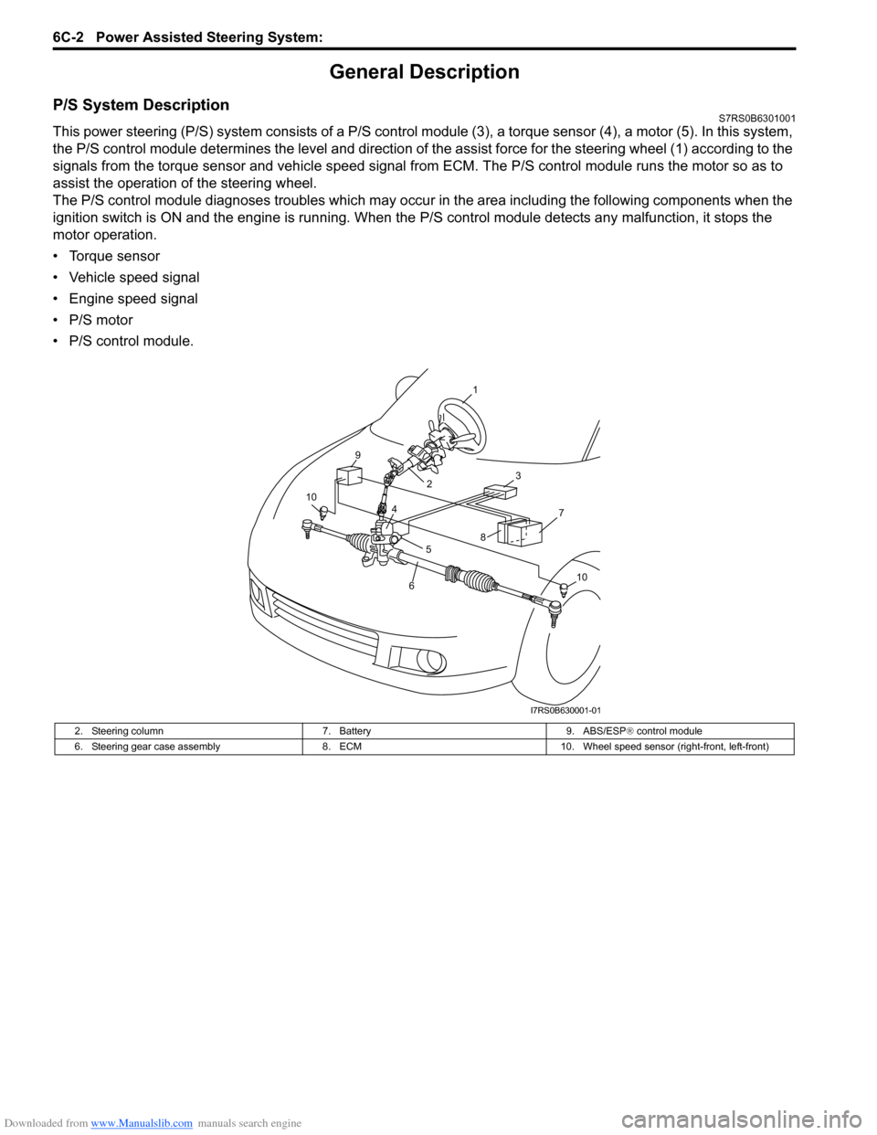
P/S System DescriptionS7RS0B6301001
This power steering (P/S) system consists of a P/S control module (3), a torque sensor (4), a motor (5). In this system,
the P/S control module determines the level and direction of the assist force for the steering wheel (1) according to the
signals from the torque sensor and vehicle speed signal from ECM. The P/S control module runs the motor so as to
assist the operation of the steering wheel.
The P/S control module diagnoses troubles which may occur in the area including the following components when the
ignition switch is ON and the engine is running. When the P/S control module detects any malfunction, it stops the
motor operation.
• Torque sensor
• Vehicle speed signal
• Engine speed signal
• P/S motor
• P/S control module.
2. Steering column 7. Battery9. ABS/ESP® control module
6. Steering gear case assembly 8. ECM10. Wheel speed sensor (right-front, left-front)
7
3
9
10
10
1
2
4
5
6
8
I7RS0B630001-01
Page 886 of 1496
Downloaded from www.Manualslib.com manuals search engine 6C-4 Power Assisted Steering System:
Schematic and Routing Diagram
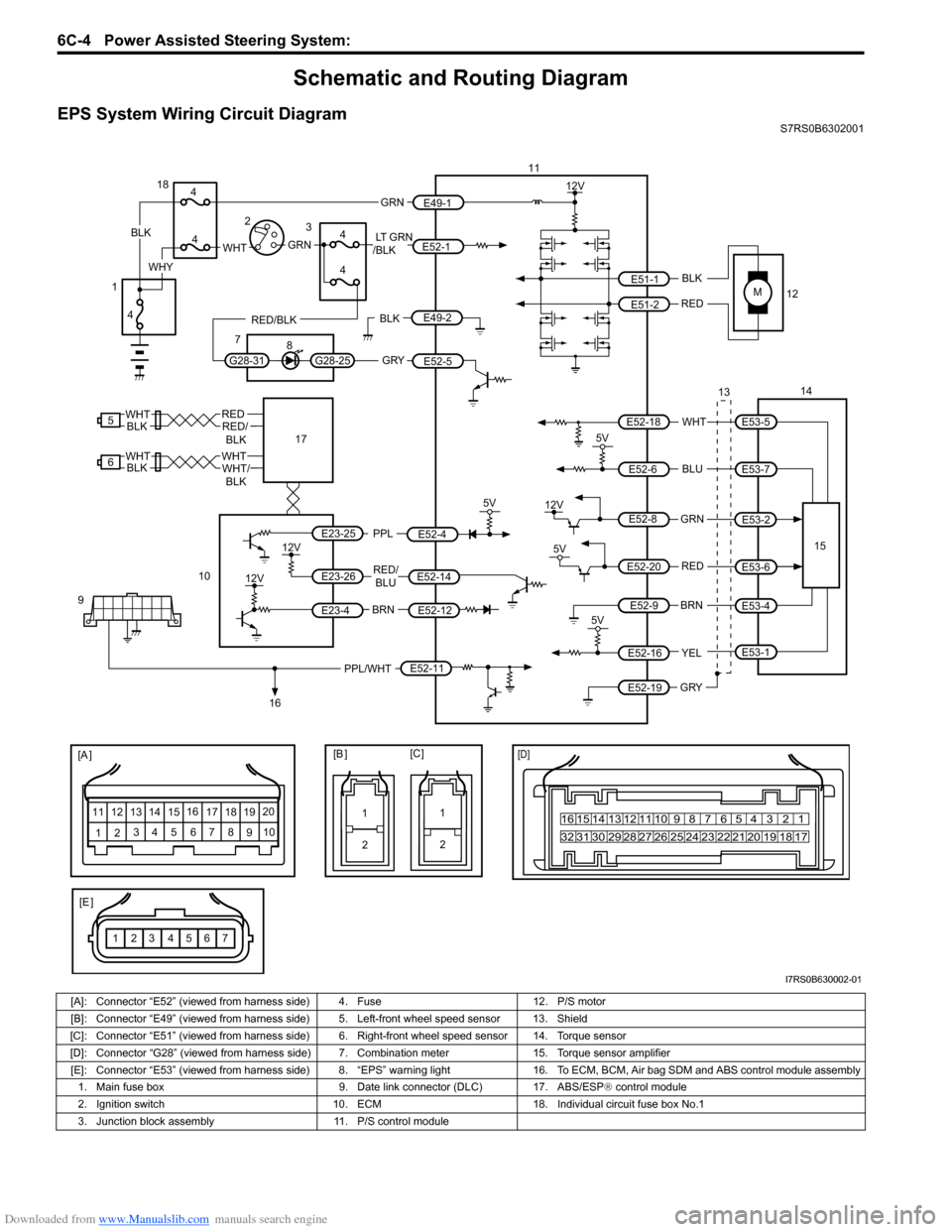
EPS System Wiring Circuit DiagramS7RS0B6302001
M
5V
BRNRED/
BLU
BLK
RED
WHT
BLU
GRN
BRN YEL
E52-11
E52-14E52-12
E23-4
E23-26
E23-25 E51-1
E51-2
E52-18
E53-5
E53-7
E52-6
E52-8
E53-2
E52-9
E52-16
E52-19
GRY
PPL/WHT
[A ]
[E ]
12 3
4 5 67
89
11
10
12 13
141516
17 18 19 20
1
2
[B ][C ]
1210 9 8 7654 3 21
16 15 14 13 12 11
26 25 24 2322 21 20 19 18 17
32 31 30 29 28 27
[D]
5V
PPL
E52-4
11
12
13 14
15
10
9
16
12V
5V
5V
12V
REDE52-20E53-6
E53-4
E53-1
7654321
5
REDRED/
BLKWHT
6WHTWHT/BLKWHTBLK
12V
12V
17BLK
GRY
LT GRN
/BLK
E52-1
E52-5
E49-1
GRNGRNWHTBLK
WHY
G28-25G28-31
RED/BLK
18
3
4
4
7 8
4
4
1 2
4
E49-2BLK
I7RS0B630002-01
[A]: Connector “E52” (viewed from harness side) 4. Fuse 12. P/S motor
[B]: Connector “E49” (viewed from harness side ) 5. Left-front wheel speed sensor 13. Shield
[C]: Connector “E51” (viewed from harness side) 6 . Right-front wheel speed sensor 14. Torque sensor
[D]: Connector “G28” (viewed from harness side) 7. Combination meter 15. Torque sensor amplifier
[E]: Connector “E53” (viewed from harness side) 8. “EPS” warning light16. To ECM, BCM, Air bag SDM and ABS control module assembly
1. Main fuse box 9. Date link connector (DLC) 17. ABS/ESP ® control module
2. Ignition switch 10. ECM18. Individual circuit fuse box No.1
3. Junction block assembly 11. P/S control module