Wiring diagram o2 sensor SUZUKI SWIFT 2006 2.G Service Workshop Manual
[x] Cancel search | Manufacturer: SUZUKI, Model Year: 2006, Model line: SWIFT, Model: SUZUKI SWIFT 2006 2.GPages: 1496, PDF Size: 34.44 MB
Page 1116 of 1496
Downloaded from www.Manualslib.com manuals search engine 8B-78 Air Bag System:
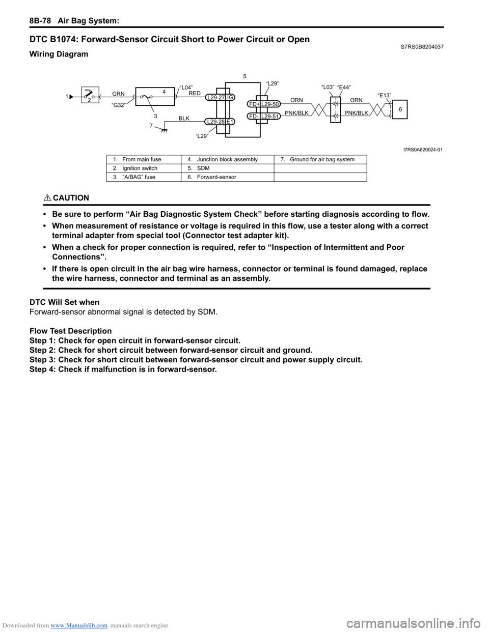
DTC B1074: Forward-Sensor Circuit Short to Power Circuit or OpenS7RS0B8204037
Wiring Diagram
CAUTION!
• Be sure to perform “Air Bag Diagnostic System Check” before starting diagnosis according to flow.
• When measurement of resistance or voltage is required in this flow, use a tester along with a correct terminal adapter from special tool (Connector test adapter kit).
• When a check for proper connection is required, refer to “Inspection of Intermittent and Poor Connections”.
• If there is open circuit in the air bag wire harnes s, connector or terminal is found damaged, replace
the wire harness, connector and terminal as an assembly.
DTC Will Set when
Forward-sensor abnormal signal is detected by SDM.
Flow Test Description
Step 1: Check for open circuit in forward-sensor circuit.
Step 2: Check for short circuit between forward-sensor circuit and ground.
Step 3: Check for short circuit between forw ard-sensor circuit and power supply circuit.
Step 4: Check if malfuncti on is in forward-sensor.
1
2
3
GRN
RED
7
BLK
L29-27
L29-28 IG
E1
4
“L29”
“L04”
“G32”
“L29”5
ORN
PNK/BLK
ORN
PNK/BLKL29-50
FD+
L29-51
FD-6
“E13”
“L03”“E44”
I7RS0A820024-01
1. From main fuse 4. Junction block assembly 7. Ground for air bag system
2. Ignition switch 5. SDM
3. “A/BAG” fuse 6. Forward-sensor
Page 1118 of 1496
Downloaded from www.Manualslib.com manuals search engine 8B-80 Air Bag System:
DTC B1081 / B1091: Driver / Passenger Side-Sensor Performance ProblemS7RS0B8204038
DTC Will Set when
SDM receives internal fault signal from side-sensor.
DTC Troubleshooting1) Turn ignition switch OFF.
2) Replace driver or passenger side-sensor referr ing to “Side-Sensor Removal and Installation”.
3) Repeat “Air Bag Diagnostic System Check”.
DTC B1082 / B1092: Driver / Passenger Side-Sensor Communication ErrorS7RS0B8204039
DTC Will Set when
Side-sensor abnormal signal is detected by SDM.
DTC Troubleshooting
1) Turn ignition switch OFF.
2) Replace driver or passenger side-sensor referr ing to “Side-Sensor Removal and Installation”.
3) Repeat “Air Bag Diagnostic System Check”.
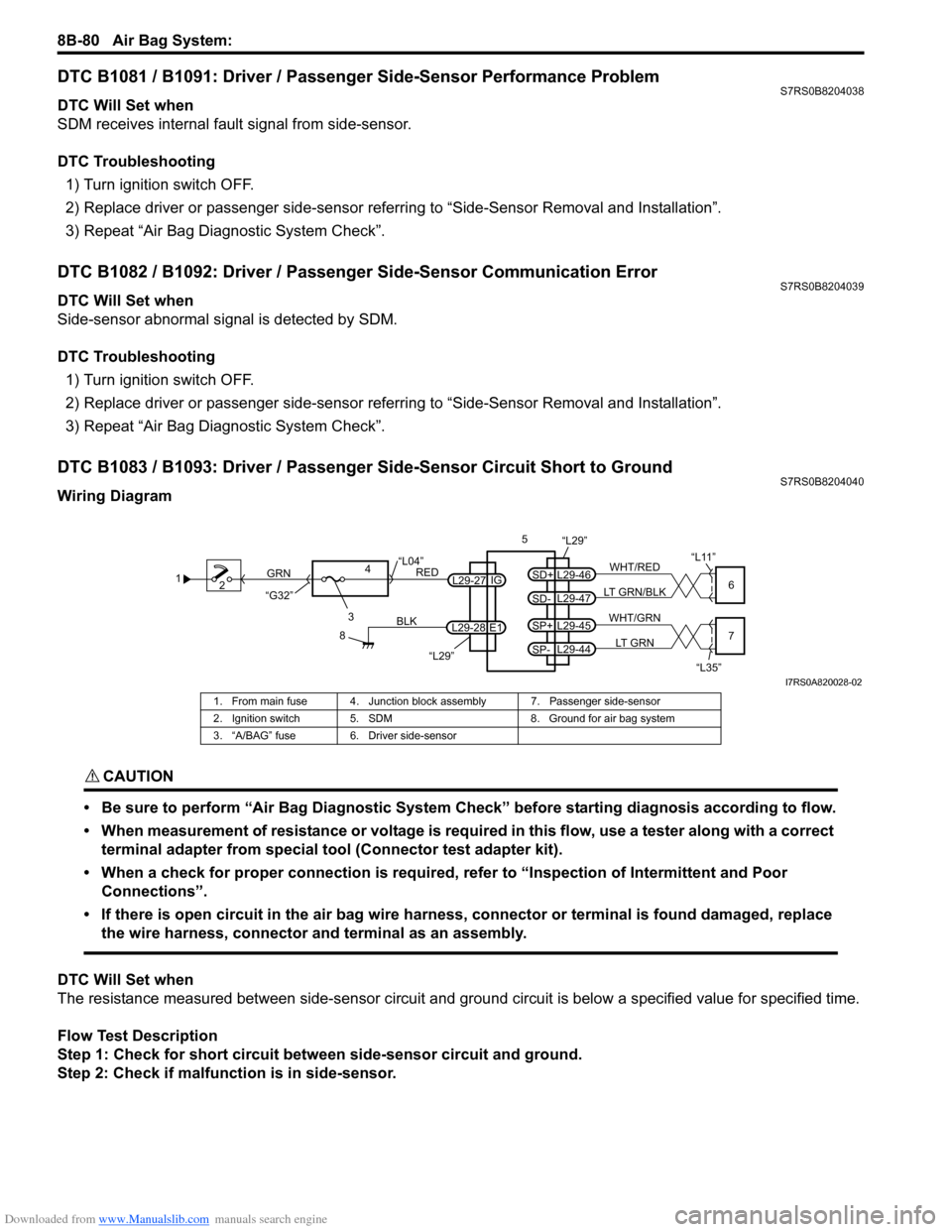
DTC B1083 / B1093: Driver / Passenger Side-Sensor Circuit Short to GroundS7RS0B8204040
Wiring Diagram
CAUTION!
• Be sure to perform “Air Bag Diagnostic System Check” before starting diagnosis according to flow.
• When measurement of resistance or voltage is required in this flow, use a tester along with a correct terminal adapter from special tool (Connector test adapter kit).
• When a check for proper connection is required, refer to “Inspection of Intermittent and Poor Connections”.
• If there is open circuit in the air bag wire harnes s, connector or terminal is found damaged, replace
the wire harness, connector and terminal as an assembly.
DTC Will Set when
The resistance measured between side-sen sor circuit and ground circuit is below a specified value for specified time.
Flow Test Description
Step 1: Check for short circuit between side-sensor circuit and ground.
Step 2: Check if malfunction is in side-sensor.
1 2
3
GRN
RED
8
BLK
L29-27
L29-28 IG
E1
4
“L29”
“L04”
“G32”
“L29”5
WHT/RED
LT GRN/BLKL29-46
SD+
L29-47
SD-6
“L11”
WHT/GRN
LT GRNL29-45
SP+
L29-44
SP-7
“L35”
I7RS0A820028-02
1. From main fuse 4. Junction blo ck assembly 7. Passenger side-sensor
2. Ignition switch 5. SDM 8. Ground for air bag system
3. “A/BAG” fuse 6. Driver side-sensor
Page 1119 of 1496
Downloaded from www.Manualslib.com manuals search engine Air Bag System: 8B-81
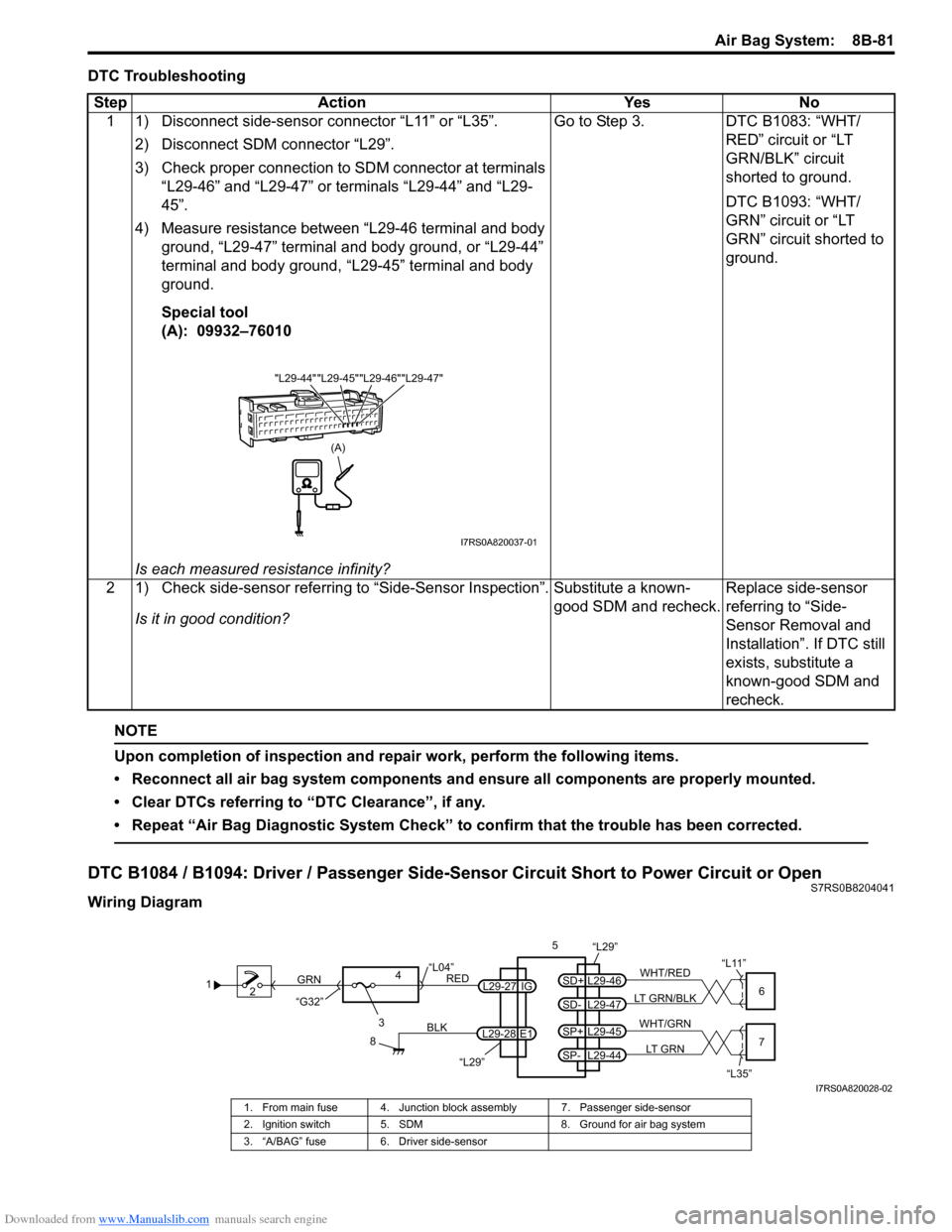
DTC Troubleshooting
NOTE
Upon completion of inspection and repair work, perform the following items.
• Reconnect all air bag system components and ensure all components are properly mounted.
• Clear DTCs referring to “DTC Clearance”, if any.
• Repeat “Air Bag Diagnostic System Check” to confirm that the trouble has been corrected.
DTC B1084 / B1094: Driver / Passenger Side-Sensor Circuit Short to Power Circuit or OpenS7RS0B8204041
Wiring DiagramStep Action Yes No
1 1) Disconnect side-sensor connector “L11” or “L35”.
2) Disconnect SDM connector “L29”.
3) Check proper connection to SDM connector at terminals “L29-46” and “L29-47” or terminals “L29-44” and “L29-
45”.
4) Measure resistance between “L29-46 terminal and body ground, “L29-47” terminal and body ground, or “L29-44”
terminal and body ground, “L29-45” terminal and body
ground.
Special tool
(A): 09932–76010
Is each measured resistance infinity? Go to Step 3. DTC B1083: “WHT/
RED” circuit or “LT
GRN/BLK” circuit
shorted to ground.
DTC B1093: “WHT/
GRN” circuit or “LT
GRN” circuit shorted to
ground.
2 1) Check side-sensor referring to “Side-Sensor Inspection”. Is it in good condition? Substitute a known-
good SDM and recheck.
Replace side-sensor
referring to “Side-
Sensor Removal and
Installation”. If DTC still
exists, substitute a
known-good SDM and
recheck.
"L29-45""L29-46""L29-47"
"L29-44"
(A)
I7RS0A820037-01
12
3
GRN
RED
8
BLK
L29-27
L29-28 IG
E1
4
“L29”
“L04”
“G32”
“L29”5
WHT/RED
LT GRN/BLKL29-46
SD+
L29-47
SD-6
“L11”
WHT/GRN
LT GRNL29-45
SP+
L29-44
SP-7
“L35”
I7RS0A820028-02
1. From main fuse 4. Junction blo ck assembly 7. Passenger side-sensor
2. Ignition switch 5. SDM 8. Ground for air bag system
3. “A/BAG” fuse 6. Driver side-sensor
Page 1175 of 1496
![SUZUKI SWIFT 2006 2.G Service Workshop Manual Downloaded from www.Manualslib.com manuals search engine Wiring Systems: 9A-4
How to Read Connector Layout DiagramS7RS0B9101004
[A-1]: Harness symbol and corresponding harness name
A: Battery harness SUZUKI SWIFT 2006 2.G Service Workshop Manual Downloaded from www.Manualslib.com manuals search engine Wiring Systems: 9A-4
How to Read Connector Layout DiagramS7RS0B9101004
[A-1]: Harness symbol and corresponding harness name
A: Battery harness](/img/20/7607/w960_7607-1174.png)
Downloaded from www.Manualslib.com manuals search engine Wiring Systems: 9A-4
How to Read Connector Layout DiagramS7RS0B9101004
[A-1]: Harness symbol and corresponding harness name
A: Battery harness
B: A/C harness
C: Engine harness
D: Injector harness
E: Main harness, Oil pressure switch wire, Console wire
G: Instrument panel harness
J: Side door wire (Power window)
K: Interior light harness, Rear speaker wire, Roof wire
L: Floor harness, G sensor wire (Fuel pump harness)
M: Rear bumper harness
O: Rear end door harness
Q: Air bag/Pretensioner harness
R: (Fuel pump wire)
[A-2]: Connector Number
[B]: Ground point No.
12
11
[B] [B]
Connector code
[A-1] [A-2]L 36
L13 L15
R01
L14
L12
L11L10
L09 L36
R02
L24
L25
L33
L28
L20 L26 (TO O01)
{
L05
L16
L32
L19
L01 (TO G01)
L02 (TO E04)
L03 (TO E05)
L42
R05
R04
L07 (TO K02)
I2RH01910901-01
Page 1217 of 1496
Downloaded from www.Manualslib.com manuals search engine Wiring Systems: 9A-46
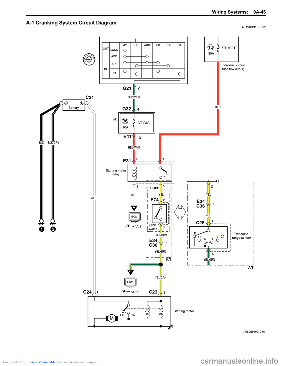
A-1 Cranking System Circuit DiagramS7RS0B910E002
Starting motorrelay
W
"A-5"
ECM
P
R N D2LTransaxle
range sensor
C28
E741
4
E31
C231C241
Starting motor
MOFF ON
BLK
1
BLK/GRY
C311
Battery
E24
C361
RED
Individual circuit
fuse box (No.1)
10
30A
36
10A
WHTWHT
M/T
IF EQPD
E24
C361
J/B
A/T
E4110
13
2
4
RED/WHT
2 ST MOT
ST SIG
YEL/GRN
YG
"A-5"
ECM
GRN/WHT
G212
YEL/GRN
YEL/GRN
YEL
YEL/GRN
YEL
YEL
G324
+B1
LOCK
ACC
ON
ST ACC IG1 IG2
STOUT
IN
+B2
21CPP
switch
2
I7RS0B910940-01
Page 1221 of 1496
Downloaded from www.Manualslib.com manuals search engine Wiring Systems: 9A-50
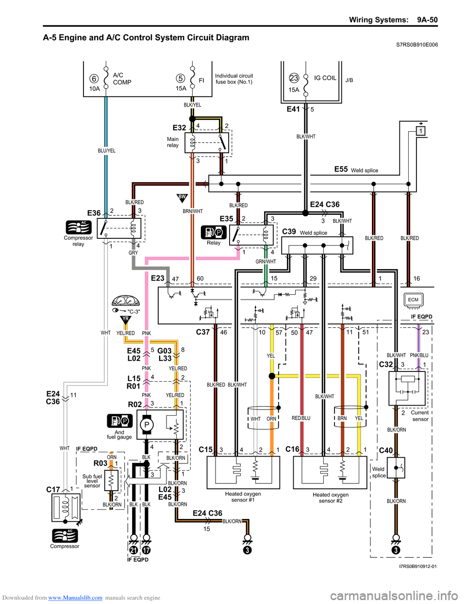
A-5 Engine and A/C Control System Circuit DiagramS7RS0B910E006
YEL/RED
E45L02 G03
L33
L02
E4558
L15
R0142
PNKYEL/RED
P
PNKYEL/RED
31
3
3 1
E24 C36
BLK/ORN
BLK/ORN
BLK/ORN
BLK/ORN
3
15
BLK
42
R02
1
2
R03
And
fuel gauge
Sub fuel level
sensor
Main
relay
1BLK/WHT
BLK/WHT
C39Weld splice Weld splice
E55
GRN/WHT
IG COILJ/B5
15A
FI
BLK/YEL
E324
32
1 15A
23
BRN/WHT
BW
YR
6
10A
A/C
COMP
Compressor
relay
E36
Relay
BLU/YEL
Compressor
C171
E415
E24 C36
3
E24
C3611
BLK/WHT
C15 C16
Heated oxygen
sensor #1
BLK/RED
WHT
Heated oxygensensor #2
BRN
BLK/WHT
RED/BLU
C37
34213421
4610574711
YEL
5123PNK
ECM
41 3
2
WHT
WHT
BLK/REDBLK/RED
BLK/RED
E23476015291
GRY
E3523
1
4
ORN
BLKBLKBLK/ORN
ORN
YEL
50
BLK/RED
16
17213
Individual circuit
fuse box (No.1)
BLK/ORN
BLK/ORN
BLK/WHTPNK/BLU
IF EQPD
IF EQPD IF EQPD
Weld
splice
C40 C32
Current
sensor
3
2 1
"C-3"
I7RS0B910912-01
Page 1226 of 1496
Downloaded from www.Manualslib.com manuals search engine 9A-55 Wiring Systems:
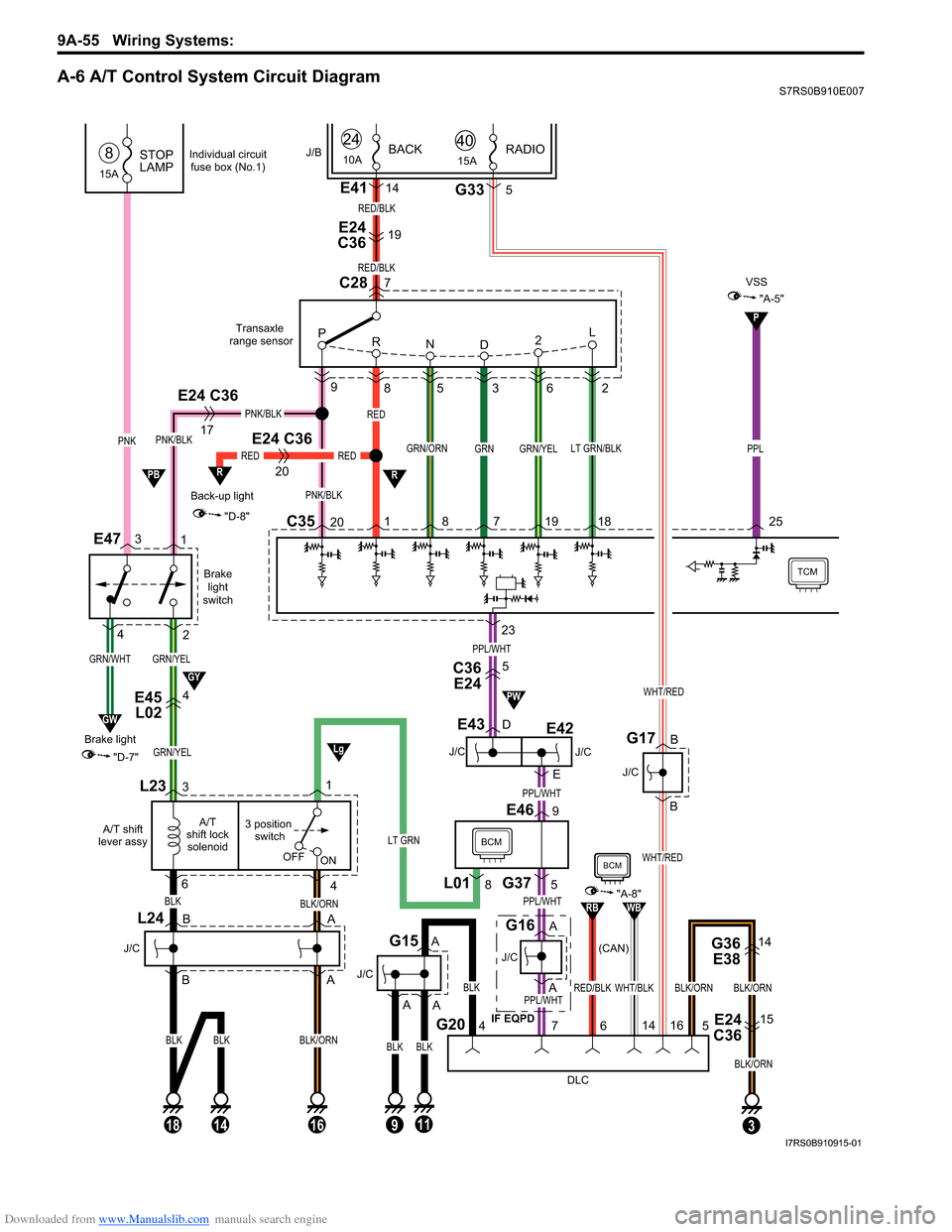
A-6 A/T Control System Circuit DiagramS7RS0B910E007
GRN/YEL
Brakelight
switch
E47
GRN/YEL
C3520 8 7 19 18
9
85 3 6 2
GRN/YEL
Back-up light
20
RED
"D-8"
R
Transaxle
range sensor
TCM
L23
4
3 position switch
A/T
shift lock solenoid
A/T shift
lever assy
BLK/ORN
16
OFF ON
RED
1
RED
BLK
PNK/BLK
GRN/ORNLT GRN/BLK
C28
P
R ND 2L
PNK/BLK
1
2
E24 C36
17
PNK/BLK
BLK
63
BLK/ORN
18
BLK
14
L24
J/C
E45
L024
J/C
E43
J/C (CAN)
G16
BCM
DLC
G207
G375
E469
4
BLK
BLKBLK
11
J/C
G15
3
G36
E3814
E24
C3615
BLK/ORNBLK/ORN
5
23
GRN
RED/BLK
7
E24
C3619
E4114
RED/BLK
PNK
15A
STOP
LAMP8
GRN/WHT
GW
"D-7"
Brake light
3
4
J/B
L018
1
24
10ABACK
A
A
B
B A
A
PPL/WHT
PPL/WHT
PPL/WHT
PPL/WHT
A
A
D
E
LT GRN
P
"A-5"
VSS
PPL
25
R
C36E245
Lg
GY
PB
PW
9
A
Individual circuit
fuse box (No.1)
WHT/BLKRED/BLK
RBWB
BCM
"A-8"
14
6
BLK/ORN
15ARADIO40
G335
WHT/RED
B
B
J/C
G17
WHT/RED
16
J/C
E42
IF EQPD
E24 C36
I7RS0B910915-01
Page 1257 of 1496
Downloaded from www.Manualslib.com manuals search engine Wiring Systems: 9A-86
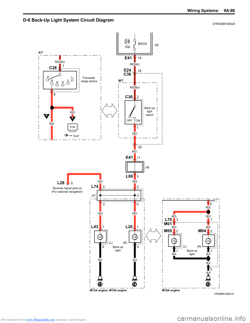
D-8 Back-Up Light System Circuit DiagramS7RS0B910E029
BLKBLK
141313
CC
C
J/C
L74CL28
Back-up light
switch
Back-up light (R)
RED
RED
RED/BLK
RED/BLK
ON
OFF J/B
10A
24BACK
E24
C3619
C302
1 20
L431L201
RED
RED
RED
M/T
L063
E4111
J/B
P R N D2LTransaxle
range sensor
RED/BLK
C28
R
RED
8
RED
"A-6"
TCM
R
E4114
7
5 5
Reverse signal pick-up
(For optional navigation)
5RED
(L)
Back-uplight (R)
(L)
M13A engine, M15A engine M16A engine
BLK
BLK
BLKBLK
F
M042
RED
REDRED
REDRED
1
M052
1
1L70
M012
3
A/T
I7RS0B910930-01
Page 1262 of 1496
Downloaded from www.Manualslib.com manuals search engine 9A-91 Wiring Systems:
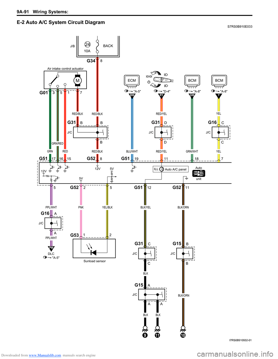
E-2 Auto A/C System Circuit DiagramS7RS0B910E033
12G53
G51
G52
G51
G52 G52 G51
251211
11
15
17
12V
198
REDGRN
RED/BLK
GRN/RED
RED/YEL
RED/YELRED/BLK
RED/BLKBLU/WHT
M
7133G01
8G34
ILL
Auto A/C panel
Sunload sensor
DLC Auto
unit
Air intake control actuator
BACK
10A24
"A-5"
PW
"A-5"BW"D-4"RY
18
GRN/WHT
"A-8"GW
ECMBCMBCM
BLK/ORN
YEL/BLKPNK
5
PPL/WHT
PPL/WHT
BLK/ORNBLK/YEL
5V 5V
12V
J/B
7
YEL
YEL
"A-8"Y
109
G31
J/C
D
D
G15
J/C
B
B
BLK
BLK
G31
J/C
C
C
G16
J/C
C
C
G15
J/C
A A
11
BLK
A
G16
J/C
A
A
J/C
BG31B B
16
5
I7RS0B910932-01
Page 1264 of 1496
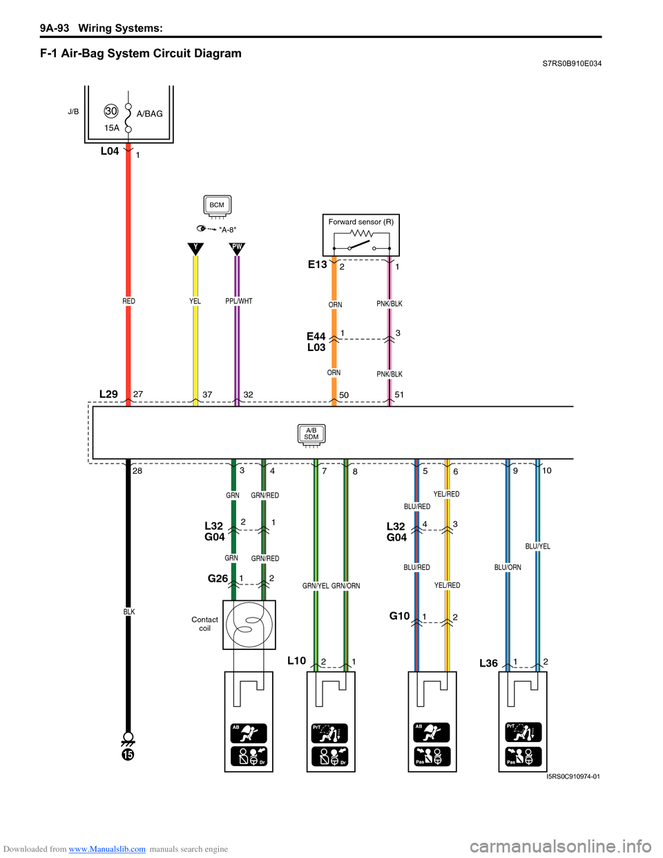
Downloaded from www.Manualslib.com manuals search engine 9A-93 Wiring Systems:
F-1 Air-Bag System Circuit DiagramS7RS0B910E034
3
ORN
YPW
A/B
SDM
L29
J/B
15A A/BAG
30
RED
L04
BCM
15
BLK
1
E44
L031
PNK/BLK
E13
Forward sensor (R)
1
2
Contact
coil
G2612
L32
G0421
L1021
YEL/RED
GRN/RED
G101 2
43
YEL/RED
L3612
3
4 7
856910
28 27
37 32 5051
"A-8"
L32
G04
ORN
PNK/BLKYELPPL/WHT
GRN
GRNGRN/RED
GRN/YELGRN/ORN
BLU/RED
BLU/REDBLU/ORN
BLU/YEL
I5RS0C910974-01