suzuki SUZUKI SWIFT 2006 2.G Service Workshop Manual
[x] Cancel search | Manufacturer: SUZUKI, Model Year: 2006, Model line: SWIFT, Model: SUZUKI SWIFT 2006 2.GPages: 1496, PDF Size: 34.44 MB
Page 896 of 1496
Downloaded from www.Manualslib.com manuals search engine 6C-14 Power Assisted Steering System:
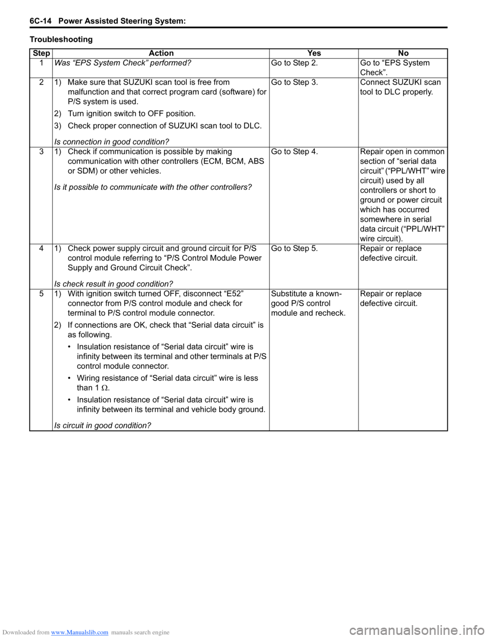
TroubleshootingStep Action Yes No 1 Was “EPS System Check” performed? Go to Step 2. Go to “EPS System
Check”.
2 1) Make sure that SUZUKI scan tool is free from malfunction and that correct program card (software) for
P/S system is used.
2) Turn ignition switch to OFF position.
3) Check proper connection of SUZUKI scan tool to DLC.
Is connection in good condition? Go to Step 3. Connect SUZUKI scan
tool to DLC properly.
3 1) Check if communication is possible by making communication with other controllers (ECM, BCM, ABS
or SDM) or other vehicles.
Is it possible to communic ate with the other controllers? Go to Step 4. Repair open in common
section of “serial data
circuit” (“PPL/WHT” wire
circuit) used by all
controllers or short to
ground or power circuit
which has occurred
somewhere in serial
data circuit (“PPL/WHT”
wire circuit).
4 1) Check power supply circuit and ground circuit for P/S control module referring to “P/S Control Module Power
Supply and Ground Circuit Check”.
Is check result in good condition? Go to Step 5. Repair or replace
defective circuit.
5 1) With ignition switch turned OFF, disconnect “E52” connector from P/S control module and check for
terminal to P/S control module connector.
2) If connections are OK, check t hat “Serial data circuit” is
as following.
• Insulation resistance of “Serial data circuit” wire is infinity between its terminal and other terminals at P/S
control module connector.
• Wiring resistance of “Seria l data circuit” wire is less
than 1 Ω.
• Insulation resistance of “Serial data circuit” wire is infinity between its terminal and vehicle body ground.
Is circuit in good condition? Substitute a known-
good P/S control
module and recheck.
Repair or replace
defective circuit.
Page 898 of 1496
Downloaded from www.Manualslib.com manuals search engine 6C-16 Power Assisted Steering System:
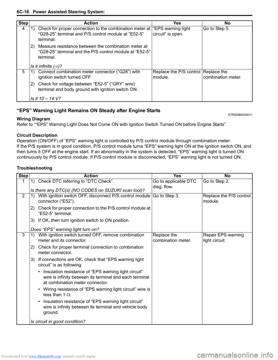
“EPS” Warning Light Remains ON Steady after Engine StartsS7RS0B6304011
Wiring Diagram
Refer to ““EPS” Warning Light Does Not Come ON with Ignition Switch Turned ON before Engine Starts”.
Circuit Description
Operation (ON/OFF) of “EPS” warning light is controlled by P/S c ontrol module through combination meter.
If the P/S system is in good condition, P/S control module tu rns “EPS” warning light ON at the ignition switch ON, and
then turns it OFF at the engine start. If an abnormality in the system is detected, “EPS” warning light is turned ON
continuously by P/S control module. If P/S control module is disconnected, “EPS” warning light is not turned ON.
Troubleshooting 4 1) Check for proper connection to the combination meter at
“G28-25” terminal and P/S control module at “E52-5”
terminal.
2) Measure resistance between the combination meter at “G28-25” terminal and the P/S control module at “E52-5”
terminal.
Is it infinite (
∞)? “EPS warning light
circuit” is open.
Go to Step 5.
5 1) Connect combination meter connector (“G28”) with ignition switch turned OFF.
2) Check for voltage between “E52-5” (“GRY” wire) terminal and body ground with ignition switch ON.
Is it 10 – 14 V? Replace the P/S control
module.
Replace the
combination meter.
Step
Action YesNo
Step Action YesNo
1 1) Check DTC referring to “DTC Check”.
Is there any DTC(s) (NO CODES on SUZUKI scan tool)? Go to applicable DTC
diag. flow.
Go to Step 2.
2 1) With ignition switch OFF, disconnect P/S control module connector (“E52”).
2) Check for proper connection to the P/S control module at “E52-5” terminal.
3) If OK, then turn ignition switch to ON position.
Does “EPS” warning light turn on? Go to Step 3.
Replace the P/S control
module.
3 1) With ignition switch turned OFF, remove combination meter and its connector.
2) Check for proper terminal connection to combination meter connector.
3) If connections are OK, ch eck that “EPS warning light
circuit” is as following.
• Insulation resistance of “EPS warning light circuit” wire is infinity between its terminal and each terminal
at combination meter connector.
• Wiring resistance of “EPS wa rning light circuit” wire is
less than 1 Ω.
• Insulation resistance of “EPS warning light circuit” wire is infinity between its terminal and vehicle body
ground.
Is circuit in good condition? Replace the
combination meter.
Repair EPS warning
light circuit.
Page 927 of 1496
Downloaded from www.Manualslib.com manuals search engine Power Assisted Steering System: 6C-45
8) Install steering gear case assembly referring to “Steering Gear Case Assembly Removal and
Installation”.
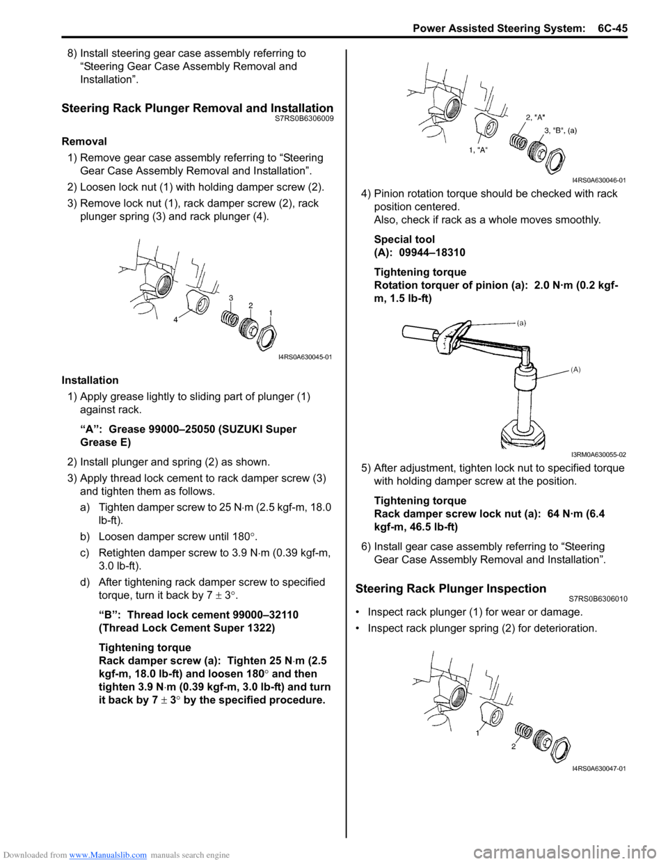
Steering Rack Plunger Removal and InstallationS7RS0B6306009
Removal
1) Remove gear case assembly referring to “Steering
Gear Case Assembly Removal and Installation”.
2) Loosen lock nut (1) with holding damper screw (2).
3) Remove lock nut (1), rack damper screw (2), rack plunger spring (3) and rack plunger (4).
Installation 1) Apply grease lightly to sliding part of plunger (1) against rack.
“A”: Grease 99000–25050 (SUZUKI Super
Grease E)
2) Install plunger and spring (2) as shown.
3) Apply thread lock cement to rack damper screw (3)
and tighten them as follows.
a) Tighten damper screw to 25 N ⋅m (2.5 kgf-m, 18.0
lb-ft).
b) Loosen damper screw until 180 °.
c) Retighten damper screw to 3.9 N ⋅m (0.39 kgf-m,
3.0 lb-ft).
d) After tightening rack damper screw to specified torque, turn it back by 7 ± 3°.
“B”: Thread lock cement 99000–32110
(Thread Lock Cement Super 1322)
Tightening torque
Rack damper screw (a): Tighten 25 N ⋅m (2.5
kgf-m, 18.0 lb-ft) and loosen 180° and then
tighten 3.9 N ⋅m (0.39 kgf-m, 3.0 lb-ft) and turn
it back by 7 ± 3° by the specified procedure. 4) Pinion rotation torque should be checked with rack
position centered.
Also, check if rack as a whole moves smoothly.
Special tool
(A): 09944–18310
Tightening torque
Rotation torquer of pinion (a): 2.0 N·m (0.2 kgf-
m, 1.5 lb-ft)
5) After adjustment, tighten lo ck nut to specified torque
with holding damper screw at the position.
Tightening torque
Rack damper screw lock nut (a): 64 N·m (6.4
kgf-m, 46.5 lb-ft)
6) Install gear case assembly referring to “Steering Gear Case Assembly Re moval and Installation”.
Steering Rack Plunger InspectionS7RS0B6306010
• Inspect rack plunger (1) for wear or damage.
• Inspect rack plunger spring (2) for deterioration.
I4RS0A630045-01
I4RS0A630046-01
I3RM0A630055-02
I4RS0A630047-01
Page 931 of 1496
Downloaded from www.Manualslib.com manuals search engine Power Assisted Steering System: 6C-49
Special Tools and Equipment
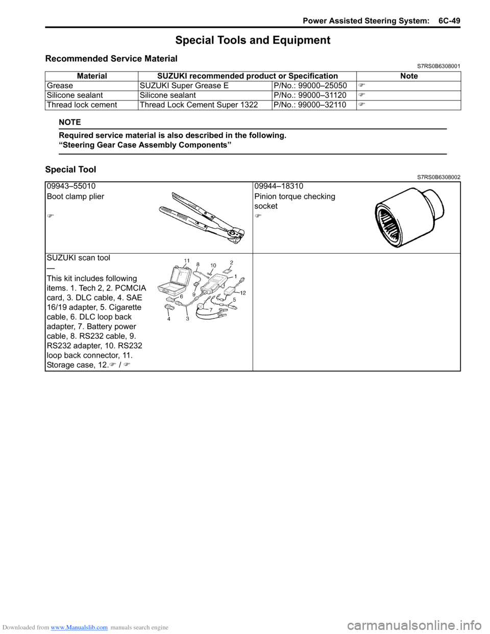
Recommended Service MaterialS7RS0B6308001
NOTE
Required service material is also described in the following.
“Steering Gear Case Assembly Components”
Special ToolS7RS0B6308002
Material SUZUKI recommended product or Specification Note
Grease SUZUKI Super Grease E P/No.: 99000–25050�)
Silicone sealant Silicone sealant P/No.: 99000–31120�)
Thread lock cement Thread Lock Cement Super 1322 P/No.: 99000–32110 �)
09943–5501009944–18310
Boot clamp plier Pinion torque checking
socket
�)�)
SUZUKI scan tool
—
This kit includes following
items. 1. Tech 2, 2. PCMCIA
card, 3. DLC cable, 4. SAE
16/19 adapter, 5. Cigarette
cable, 6. DLC loop back
adapter, 7. Battery power
cable, 8. RS232 cable, 9.
RS232 adapter, 10. RS232
loop back connector, 11.
Storage case, 12. �) / �)
Page 978 of 1496
Downloaded from www.Manualslib.com manuals search engine 7B-30 Air Conditioning System: Manual Type
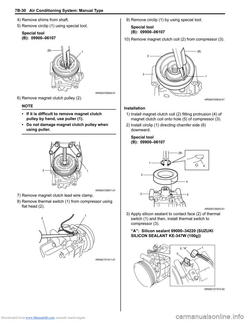
4) Remove shims from shaft.
5) Remove circlip (1) using special tool.Special tool
(B): 09900–06107
6) Remove magnet clutch pulley (2).
NOTE
• If it is difficult to remove magnet clutch pulley by hand, use puller (1).
• Do not damage magnet clutch pulley when using puller.
7) Remove magnet clutch lead wire clamp.
8) Remove thermal switch (1) from compressor using flat head (2). 9) Remove circlip (1) by using special tool.
Special tool
(B): 09900–06107
10) Remove magnet clutch coil (2) from compressor (3).
Installation 1) Install magnet clutch coil (2) fitting protrusion (4) of magnet clutch coil onto hole (5) of compressor (3).
2) Install circlip (1) dire cting chamfer side (6)
downward.
Special tool
(B): 09900–06107
3) Apply silicon sealant to co ntact face (2) of thermal
switch (1) and then, inst all thermal switch to
compressor (3).
“A”: Silicon sealant 99000–34220 (SUZUKI
SILICON SEALANT KE-347W (100g))
(B) 1
I4RS0A720040-01
1
2
I4RS0A720041-01
2 1
I5RS0C721011-01
1
(B)
23
I4RS0A720042-01
1 (B)
2
3 4
5 6
I4RS0A720043-01
3
2, “A”1
I5RS0C721012-02
Page 981 of 1496
Downloaded from www.Manualslib.com manuals search engine Air Conditioning System: Manual Type 7B-33
Special Tools and Equipment
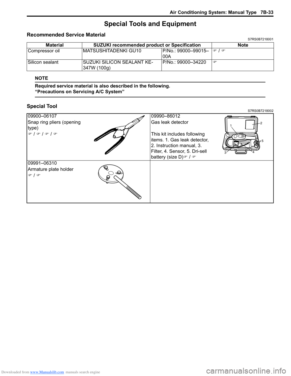
Recommended Service MaterialS7RS0B7218001
NOTE
Required service material is also described in the following.
“Precautions on Servicing A/C System”
Special ToolS7RS0B7218002
Material SUZUKI recommended product or Specification Note
Compressor oil MATSUSHITADEN KI GU10 P/No.: 99000–99015–
00A �)
/ �)
Silicon sealant SUZUKI SILICON SEALANT KE-
347W (100g) P/No.: 99000–34220
�)
09900–06107 09990–86012
Snap ring pliers (opening
type) Gas leak detector
�) / �) / �) / �) This kit includes following
items. 1. Gas leak detector,
2. Instruction manual, 3.
Filter, 4. Sensor, 5. Dri-sell
battery (size D)�) / �)
09991–06310
Armature plate holder
�) / �)
1 2
3 4
5
Page 982 of 1496
Downloaded from www.Manualslib.com manuals search engine 7B-34 Air Conditioning System: Automatic Type
Automatic Type
Precautions
A/C System CautionS7RS0B7220001
Refer to “A/C System Caution”.
Precautions in Diagnosing TroubleS7RS0B7220002
• Do not disconnect couplers from HVAC control module, battery cable from battery, HVAC control module ground
wire harness from body or main fuse before confirming diagnostic information (diagnostic trouble code) stored in
HVAC control module memory.
• Diagnostic information (diagnostic trouble code) stored in HVAC control module can be checked by display of HVAC
control module. Also, it can be checked by using SU ZUKI scan tool. Before checking diagnostic information
(diagnostic trouble code), read this manual and operator's manual for SUZUKI scan tool to know how to read
diagnostic information (diagnostic trouble code).
• When trouble is diagnosed using diagnostic information (diagnostic trouble code) on display of HVAC control
module, keep in your mind that each diagnostic inform ation (diagnostic trouble code) has priority, and only
diagnostic information (diagnostic troub le code) which has the highest priority is indicated. Therefore, after
troubleshooting the malfunction, make sure if there exists any other diagnostic information (diagnostic trouble
code).
• Be sure to read “Precautions for Electrical Circuit Service in Section 00” before inspection.
Precautions on Servicing A/C SystemS7RS0B7220003
Refer to “Precautions on Servicing A/C System”.
General Description
Auto A/C System DescriptionS7RS0B7221001
The automatic type air conditioning system (auto A/C) is pr ovided with the function to automatically control the inside
air temperature, fan speed, air flow outl et direction and air intake position by HVAC control module in addition to
functions of the manual type air conditioning system (manua l A/C). Once the inside air temperature is set using the
temperature selector, HVAC control module automatically controls the inside air temperature at the constant level at all
times based on the inside air temperature, outside ai r temperature, amount of sunlight and engine coolant
temperature detected respectively by the inside air te mperature sensor, outside air temperature sensor, sunload
sensor and ECT sensor. At this time, “FULL AUTO A/ C” appears on the display of HVAC control module.
With the air intake selector pushed in the above state, it is possible to select any position of the air intake actuator.
Then, “FULL AUTO A/C” on the display changes to “AUTO A/C”.
Page 985 of 1496
Downloaded from www.Manualslib.com manuals search engine Air Conditioning System: Automatic Type 7B-37
On-Board Diagnostic System DescriptionS7RS0B7221007
NOTE
The diagnostic information as diagnostic
trouble code (DTC) can be known by using
SUZUKI scan tool. For further details, refer to
“DTC Check”.
HVAC control module detect s malfunctions, which may
occur in the following area.
• Outside air temperature sensor
• Inside air temperature sensor
• Evaporator temperature sensor
• Sunload sensor
• ECT sensor
• Temperature control actuator of HVAC unit
• Air flow control actuator of HVAC unit
• A/C refrigerant pressure sensor • HVAC control module
• VSS
• Serial Communication line
• CAN communication line
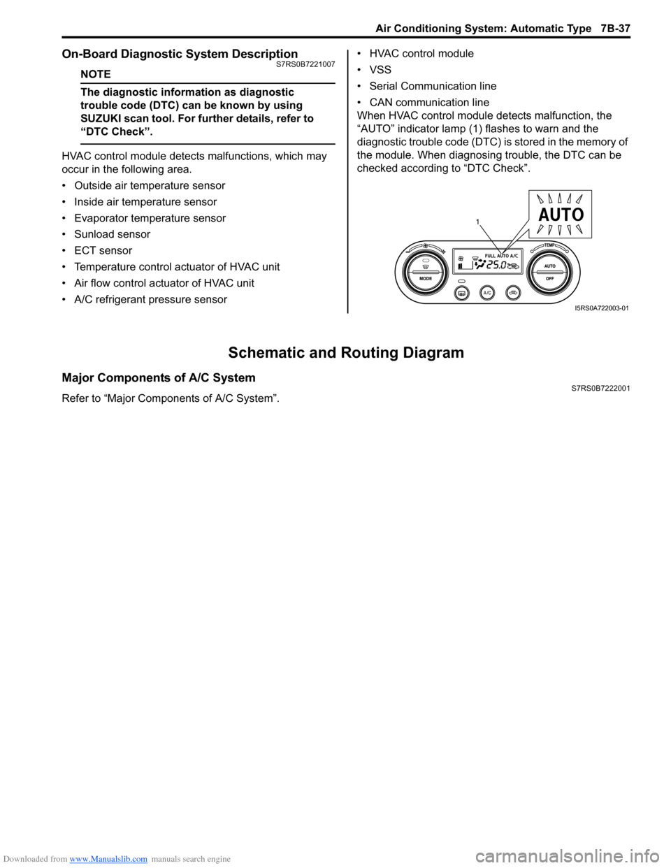
When HVAC control module detects malfunction, the
“AUTO” indicator lamp (1) flashes to warn and the
diagnostic trouble code (DTC) is stored in the memory of
the module. When diagnosing trouble, the DTC can be
checked according to “DTC Check”.
Schematic and Routing Diagram
Major Components of A/C SystemS7RS0B7222001
Refer to “Major Components of A/C System”.
1
I5RS0A722003-01
Page 990 of 1496
Downloaded from www.Manualslib.com manuals search engine 7B-42 Air Conditioning System: Automatic Type
Abnormal Noise Symptom Diagnosis of A/C
System
S7RS0B7224002
Refer to “Abnormal Noise Symptom Diagnosis of A/C
System”.
DTC CheckS7RS0B7224003
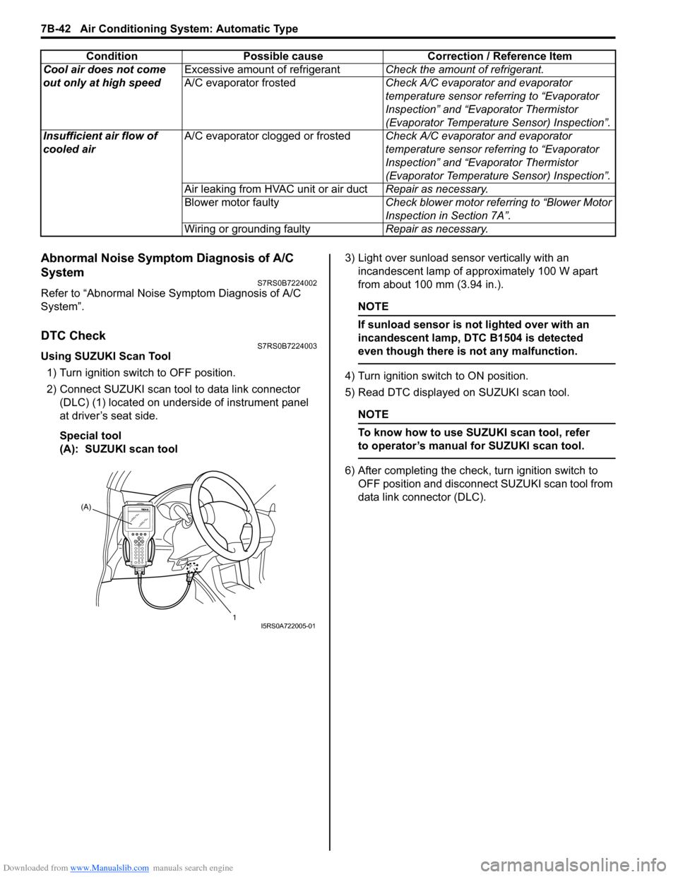
Using SUZUKI Scan Tool1) Turn ignition switch to OFF position.
2) Connect SUZUKI scan tool to data link connector (DLC) (1) located on underside of instrument panel
at driver’s seat side.
Special tool
(A): SUZUKI scan tool 3) Light over sunload sensor vertically with an
incandescent lamp of approximately 100 W apart
from about 100 mm (3.94 in.).
NOTE
If sunload sensor is not lighted over with an
incandescent lamp, DTC B1504 is detected
even though there is not any malfunction.
4) Turn ignition switch to ON position.
5) Read DTC displayed on SUZUKI scan tool.
NOTE
To know how to use SUZUKI scan tool, refer
to operator’s manual for SUZUKI scan tool.
6) After completing the check, turn ignition switch to
OFF position and disconnect SUZUKI scan tool from
data link connector (DLC).
Cool air does not come
out only at high speed
Excessive amount of refrigerant
Check the amount of refrigerant.
A/C evaporator frosted Check A/C evaporator and evaporator
temperature sensor referring to “Evaporator
Inspection” and “Evaporator Thermistor
(Evaporator Temperature Sensor) Inspection”.
Insufficient air flow of
cooled air A/C evaporator clogged or frosted
Check A/C evaporator and evaporator
temperature sensor referring to “Evaporator
Inspection” and “Evaporator Thermistor
(Evaporator Temperature Sensor) Inspection”.
Air leaking from HVAC unit or air duct Repair as necessary.
Blower motor faulty Check blower motor referring to “Blower Motor
Inspection in Section 7A”.
Wiring or grounding faulty Repair as necessary.
Condition Possible cause Correction / Reference Item
(A)
1
I5RS0A722005-01
Page 991 of 1496
Downloaded from www.Manualslib.com manuals search engine Air Conditioning System: Automatic Type 7B-43
Not Using SUZUKI Scan Tool
Current DTC mode1) Light over sunload sensor vertically with an incandescent lamp of approximately 100 W apart
from about 100 mm (3.94 in.).
NOTE
If sunload sensor is not lighted over with an
incandescent lamp, DTC B1504 is detected
as current DTC even though there is not any
malfunction.
2) Start engine.
3) Wait for 20 seconds or more after engine started and set temperature selector to 25 °C (77 °F).
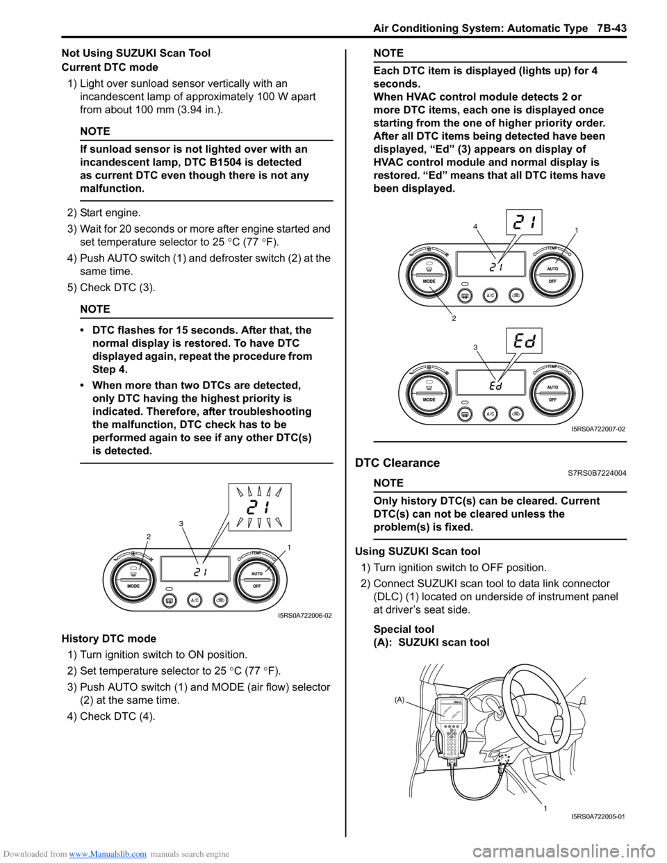
4) Push AUTO switch (1) and defroster switch (2) at the same time.
5) Check DTC (3).
NOTE
• DTC flashes for 15 seconds. After that, the normal display is rest ored. To have DTC
displayed again, repeat the procedure from
Step 4.
• When more than two DTCs are detected, only DTC having the highest priority is
indicated. Therefore, after troubleshooting
the malfunction, DTC check has to be
performed again to see if any other DTC(s)
is detected.
History DTC mode
1) Turn ignition switch to ON position.
2) Set temperature selector to 25 °C (77 °F).
3) Push AUTO switch (1) and MODE (air flow) selector
(2) at the same time.
4) Check DTC (4).
NOTE
Each DTC item is displayed (lights up) for 4
seconds.
When HVAC control module detects 2 or
more DTC items, each one is displayed once
starting from the one of higher priority order.
After all DTC items being detected have been
displayed, “Ed” (3) appears on display of
HVAC control module and normal display is
restored. “Ed” means that all DTC items have
been displayed.
DTC ClearanceS7RS0B7224004
NOTE
Only history DTC(s) can be cleared. Current
DTC(s) can not be cleared unless the
problem(s) is fixed.
Using SUZUKI Scan tool
1) Turn ignition switch to OFF position.
2) Connect SUZUKI scan tool to data link connector (DLC) (1) located on underside of instrument panel
at driver’s seat side.
Special tool
(A): SUZUKI scan tool1
2
3
I5RS0A722006-02
1
2 34
I5RS0A722007-02
(A)
1
I5RS0A722005-01