Body SUZUKI SWIFT 2006 2.G Service Workshop Manual
[x] Cancel search | Manufacturer: SUZUKI, Model Year: 2006, Model line: SWIFT, Model: SUZUKI SWIFT 2006 2.GPages: 1496, PDF Size: 34.44 MB
Page 302 of 1496

Downloaded from www.Manualslib.com manuals search engine 1D-17 Engine Mechanical:
Engine Assembly Removal and InstallationS7RS0B1406011
NOTE
After replacing electric throttle body
assembly, perform calibration of throttle
valve referring to “Electric Throttle Body
System Calibration in Section 1C”.
Removal1) Relieve fuel pressure according to “Fuel Pressure Relief Procedure in Section 1G”.
2) Disconnect negative and pos itive cable at battery.
3) Remove battery and tray.
4) Remove engine hood after disconnecting windshield washer hose.
5) Remove right and left side engine under covers.
6) Remove A/C compressor belt by referring to “Compressor Drive Belt Remo val and Installation in
Section 7B” or “Compressor Drive Belt Removal and
Installation in Section 7B”.
7) Drain engine oil, transaxle oil and coolant.
8) Remove cowl top plate referring to “Cowl Top Components in Section 9K”.
9) Remove air cleaner assembly referring to “Air Cleaner Components”.
10) With hose connected, detach A/C compressor from its bracket (A/C model) referring to “Compressor
Assembly Removal and Installation in Section 7B” or
“Compressor Assembly Removal and Installation in
Section 7B”.
CAUTION!
Suspend removed A/C compressor at a place
where no damage will be caused during
removal and installation of engine assembly.
11) Remove intake manifold rear stiffener (1) from intake manifold and cylinder block. 12) Disconnect the following electric wires:
• MAP sensor (1)
• ECT sensor (2)
•EGR valve (3)
• CMP sensor (4)
• Electric throttle body assembly (5)
• Ignition coil assembly (6)
• Injectors (7)
• Heated oxygen sensor No. 2 (8) and No. 1 (9)
• Oil control valve (10)
• Engine oil pressure switch (11)
• CKP sensor (12)
• Knock sensor (13)
• Back up light switch (14)
• Generator (15)
• Starting motor (16)
• Ground terminal (17) from intake manifold
• Battery ground terminal (18) from exhaust manifold
• Battery ground cable (19) from transaxle
• Magnet clutch switch of A/C compressor (A/C model)
• Each wire harness clamps
• Output shaft speed sensor (VSS) (34) (A/T model)
• Solenoid valve (33) (A/T model)
• Transmission range sensor (32) (A/T model)
• Input shaft speed sensor (31) (A/T model)
13) Remove fuse box from its bracket.
14) Disconnect the following cables: • Gear select control cable (23) (M/T model)
• Gear shift control cable (24) (M/T model)
• A/T select cable (A/T model)
15) Disconnect the following hoses: • Brake booster hose (26) from intake manifold
• Radiator inlet and outlet hoses (20) from each pipe
• Heater inlet and outlet hoses (21) from each pipe
• Fuel feed hoses (22) from fuel feed pipe
• EVAP canister purge valve hose (30) from purge pipe
• A/T fluid cooler hoses (A/T model)
16) With hose connected, detach clutch operating cylinder (25). (M/T model)
CAUTION!
Suspend removed clutch operating cylinder
at a place where no damage will be caused
during removal and installation of engine
assembly.
1
I6RS0B141014-01
Page 312 of 1496
Downloaded from www.Manualslib.com manuals search engine 1D-27 Engine Mechanical:
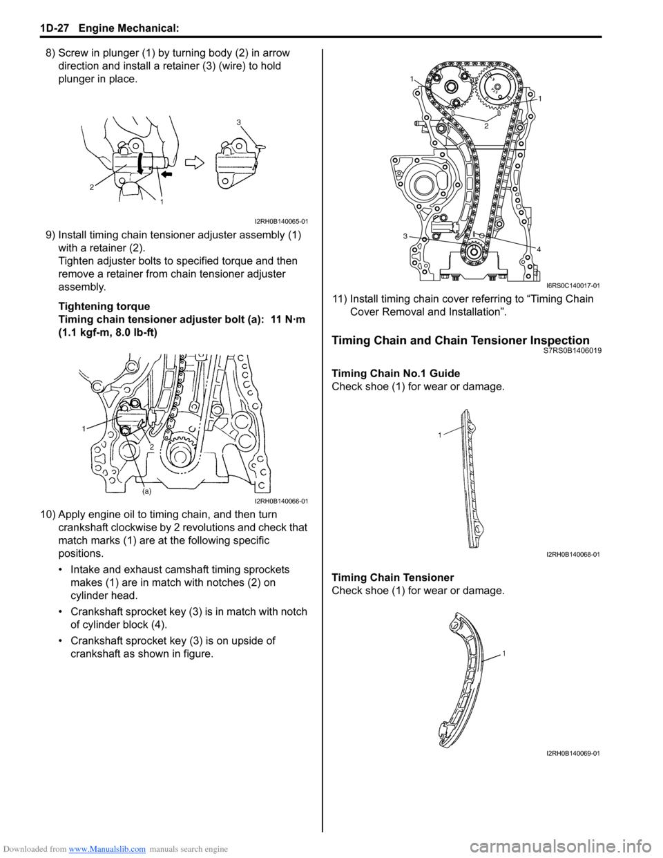
8) Screw in plunger (1) by turning body (2) in arrow direction and install a reta iner (3) (wire) to hold
plunger in place.
9) Install timing chain tensioner adjuster assembly (1) with a retainer (2).
Tighten adjuster bolts to specified torque and then
remove a retainer from chain tensioner adjuster
assembly.
Tightening torque
Timing chain tensioner adjuster bolt (a): 11 N·m
(1.1 kgf-m, 8.0 lb-ft)
10) Apply engine oil to timing chain, and then turn crankshaft clockwise by 2 revolutions and check that
match marks (1) are at the following specific
positions.
• Intake and exhaust camshaft timing sprockets makes (1) are in match with notches (2) on
cylinder head.
• Crankshaft sprocket key (3) is in match with notch of cylinder block (4).
• Crankshaft sprocket key (3) is on upside of crankshaft as shown in figure. 11) Install timing chain cover referring to “Timing Chain
Cover Removal and Installation”.
Timing Chain and Chain Tensioner InspectionS7RS0B1406019
Timing Chain No.1 Guide
Check shoe (1) for wear or damage.
Timing Chain Tensioner
Check shoe (1) for wear or damage.
I2RH0B140065-01
I2RH0B140066-01
1
1
2
3 4
I6RS0C140017-01
I2RH0B140068-01
I2RH0B140069-01
Page 350 of 1496
Downloaded from www.Manualslib.com manuals search engine 1D-65 Engine Mechanical:
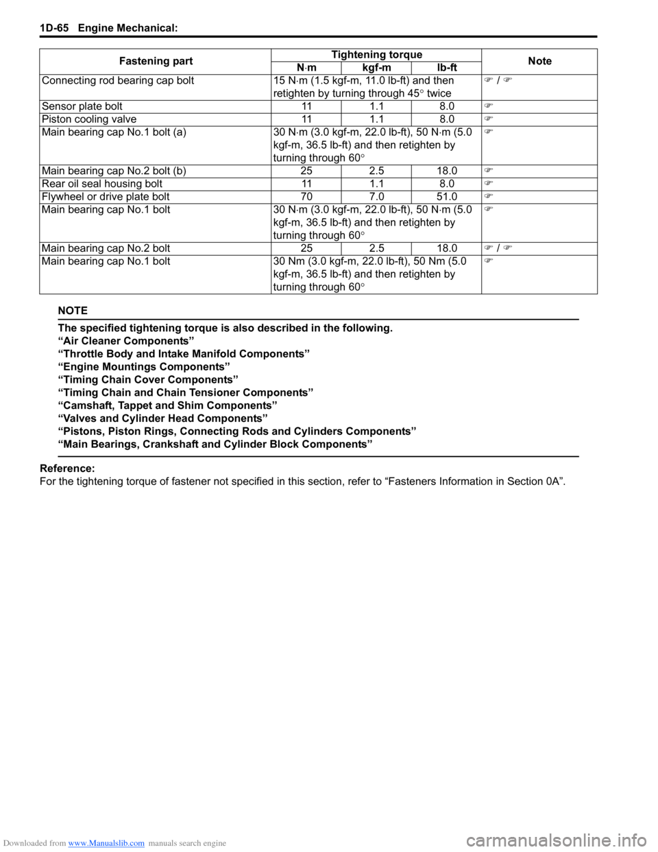
NOTE
The specified tightening torque is also described in the following.
“Air Cleaner Components”
“Throttle Body and Intake Manifold Components”
“Engine Mountings Components”
“Timing Chain Cover Components”
“Timing Chain and Chain Tensioner Components”
“Camshaft, Tappet and Shim Components”
“Valves and Cylinder Head Components”
“Pistons, Piston Rings, Connecting Rods and Cylinders Components”
“Main Bearings, Crankshaft and Cylinder Block Components”
Reference:
For the tightening torque of fastener not specified in this section, refer to “Fasteners Information in Section 0A”.
Connecting rod bearing cap bolt
15 N⋅m (1.5 kgf-m, 11.0 lb-ft) and then
retighten by turning through 45 ° twice �)
/ �)
Sensor plate bolt 111.1 8.0 �)
Piston cooling valve 111.1 8.0 �)
Main bearing cap No.1 bolt (a) 30 N⋅m (3.0 kgf-m, 22.0 lb-ft), 50 N ⋅m (5.0
kgf-m, 36.5 lb-ft) and then retighten by
turning through 60 ° �)
Main bearing cap No.2 bolt (b) 252.5 18.0 �)
Rear oil seal housing bolt 111.1 8.0 �)
Flywheel or drive plate bolt 707.0 51.0 �)
Main bearing cap No.1 bolt 30 N⋅m (3.0 kgf-m, 22.0 lb-ft), 50 N ⋅m (5.0
kgf-m, 36.5 lb-ft) and then retighten by
turning through 60 ° �)
Main bearing cap No.2 bolt 252.5 18.0 �) / �)
Main bearing cap No.1 bolt 30 Nm (3.0 kgf-m, 22.0 lb-ft), 50 Nm (5.0
kgf-m, 36.5 lb-ft) and then retighten by
turning through 60 ° �)
Fastening part
Tightening torque
Note
N ⋅mkgf-mlb-ft
Page 365 of 1496
Downloaded from www.Manualslib.com manuals search engine Engine Cooling System: 1F-2
Coolant capacity
For M/T model:• Engine, radiator and heater: 5.5 liters (11.62/9.68 US/lmp pt.)
• Reservoir: 0.7 liters (1.48/1.23 US/lmp pt.)
• Total: 6.2 liters (13.10/10.91 US/lmp pt.)
For A/T model: • Engine, radiator and heater: 5.4 liters (11.41/9.50 US/lmp pt.)
• Reservoir: 0.7 liters (1.48/1.23 US/lmp pt.)
• Total: 6.1 liters (12.89/10.74 US/lmp pt.)
Schematic and Routing Diagram
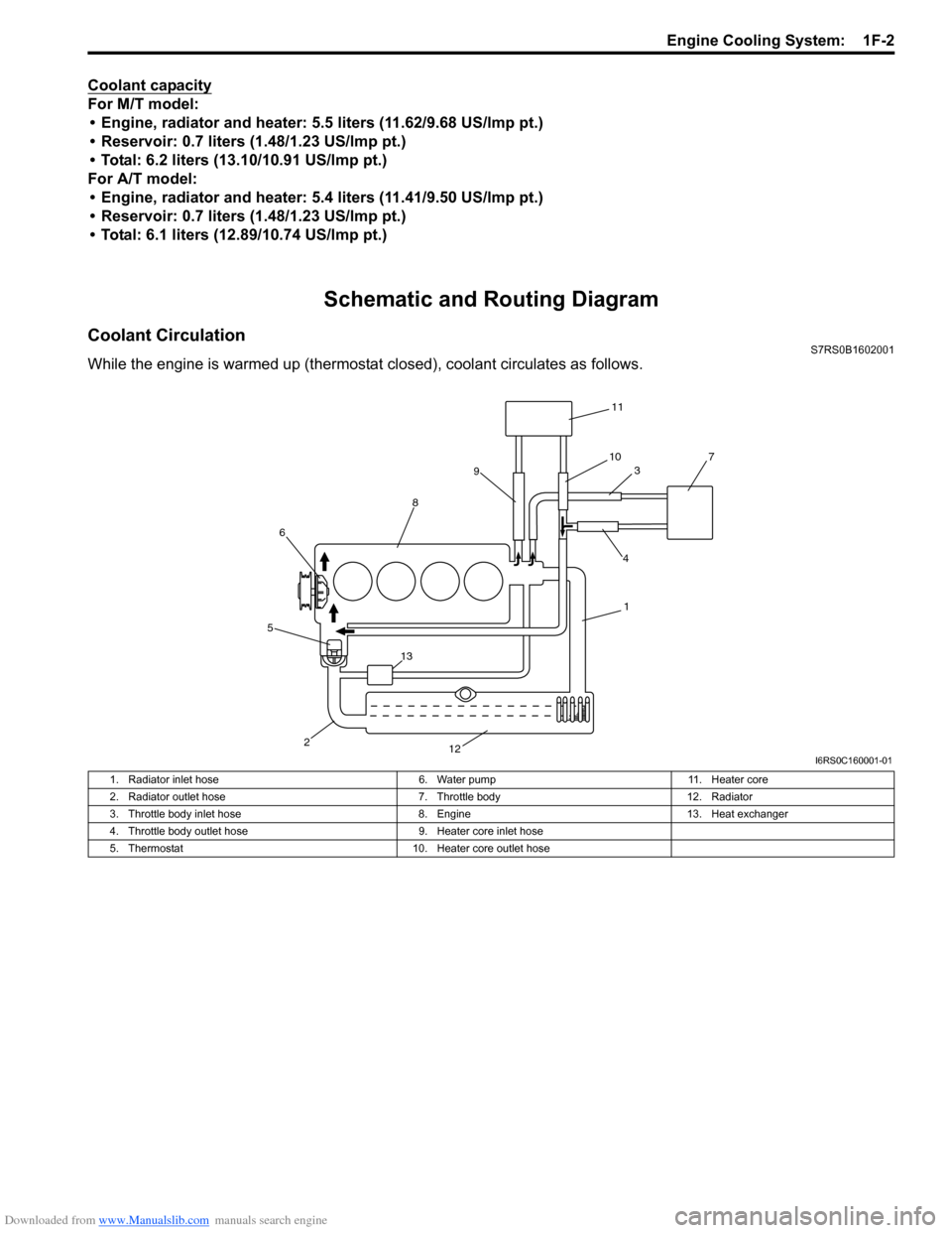
Coolant CirculationS7RS0B1602001
While the engine is warmed up (thermosta t closed), coolant circulates as follows.
11
10 3 7
4
9
8
6
5
2 12 1
13
I6RS0C160001-01
1. Radiator inlet hose
6. Water pump11. Heater core
2. Radiator outlet hose 7. Throttle body12. Radiator
3. Throttle body inlet hose 8. Engine13. Heat exchanger
4. Throttle body outlet hose 9. Heater core inlet hose
5. Thermostat 10. Heater core outlet hose
Page 366 of 1496
Downloaded from www.Manualslib.com manuals search engine 1F-3 Engine Cooling System:
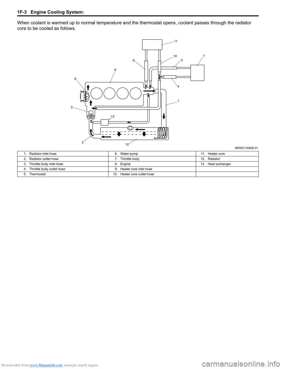
When coolant is warmed up to normal temperature and the thermostat opens, coolant passes through the radiator
core to be cooled as follows.
11
10 3 7
4
9
8
6
5
2 12 1
13
I6RS0C160002-01
1. Radiator inlet hose
6. Water pump11. Heater core
2. Radiator outlet hose 7. Throttle body12. Radiator
3. Throttle body inlet hose 8. Engine13. Heat exchanger
4. Throttle body outlet hose 9. Heater core inlet hose
5. Thermostat 10. Heater core outlet hose
Page 368 of 1496
Downloaded from www.Manualslib.com manuals search engine 1F-5 Engine Cooling System:
Repair Instructions
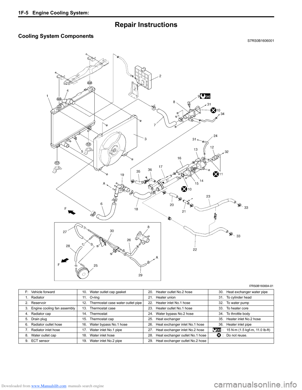
Cooling System ComponentsS7RS0B1606001
I7RS0B160004-01
F: Vehicle forward10. Water outlet cap gasket 20. Heater outlet No.2 hose 30. Heat exchanger water pipe
1. Radiator 11. O-ring 21. Heater union 31. To cylinder head
2. Reservoir 12. Thermostat case water outlet pipe 22. Heater inlet No.1 hose 32. To water pump
3. Engine cooling fan assembly 13. Thermostat case 23. Heater outlet No.1 hose33. To heater core
4. Radiator cap 14. Thermostat 24. Water bypass No.2 hose 34. To throttle body
5. Drain plug 15. Thermostat cap 25. Heat exchanger 35. Heater inlet No.2 hose
6. Radiator outlet hose 16. Water bypass No.1 hose 26.Heat exchanger inlet No.1 hose 36. Heater inlet pipe
7. Radiator inlet hose 17. Water inlet No.1 pipe 27. Heat exchanger inlet No.2 hose : 15 N⋅m (1.5 kgf-m, 11.0 lb-ft)
8. Water outlet cap 18. Water inlet hose 28. Heat exchanger outlet No.1 hose : Do not reuse.
9. ECT sensor 19. Water inlet No.2 pipe 29. Heat exchanger outlet No.2 hose
Page 392 of 1496
Downloaded from www.Manualslib.com manuals search engine 1G-17 Fuel System:
Special Tools and Equipment
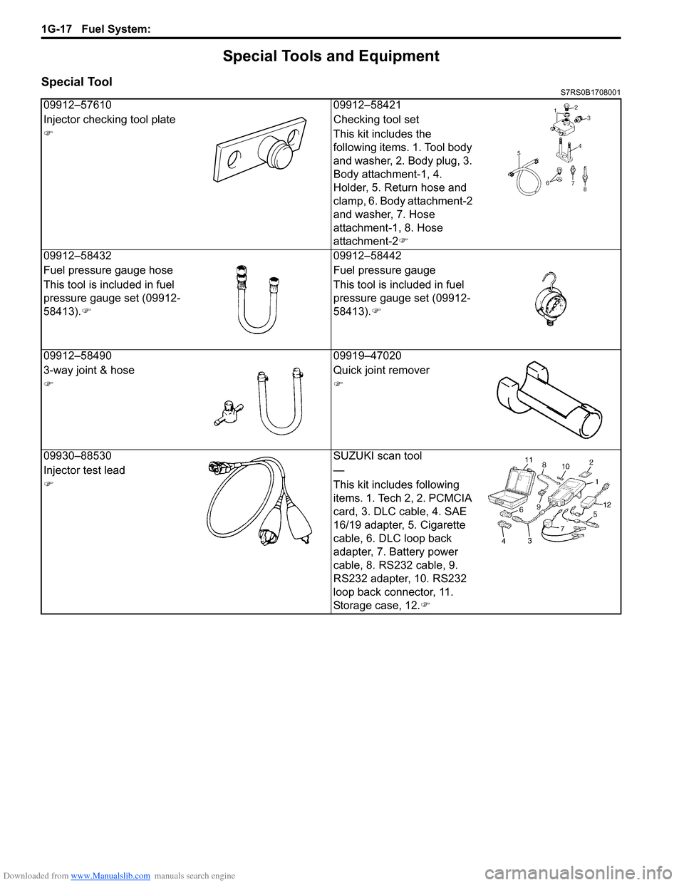
Special ToolS7RS0B1708001
09912–5761009912–58421
Injector checking tool plate Checking tool set
�) This kit includes the
following items. 1. Tool body
and washer, 2. Body plug, 3.
Body attachment-1, 4.
Holder, 5. Return hose and
clamp, 6. Body attachment-2
and washer, 7. Hose
attachment-1, 8. Hose
attachment-2�)
09912–58432 09912–58442
Fuel pressure gauge hose Fuel pressure gauge
This tool is included in fuel
pressure gauge set (09912-
58413). �) This tool is included in fuel
pressure gauge set (09912-
58413).
�)
09912–58490 09919–47020
3-way joint & hose Quick joint remover
�)�)
09930–88530 SUZUKI scan tool
Injector test lead —
�) This kit includes following
items. 1. Tech 2, 2. PCMCIA
card, 3. DLC cable, 4. SAE
16/19 adapter, 5. Cigarette
cable, 6. DLC loop back
adapter, 7. Battery power
cable, 8. RS232 cable, 9.
RS232 adapter, 10. RS232
loop back connector, 11.
Storage case, 12.�)
Page 395 of 1496
Downloaded from www.Manualslib.com manuals search engine Ignition System: 1H-3
Component Location
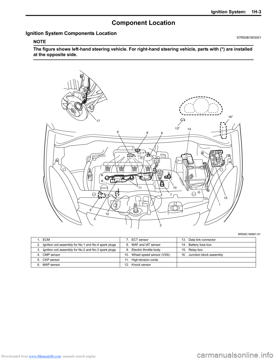
Ignition System Components LocationS7RS0B1803001
NOTE
The figure shows left-hand steering vehicle. For right-hand steering vehicle, parts with (*) are installed
at the opposite side.
16*
1
2
14
7
5 12 11
410
6
89
3 13*
15
17
I6RS0C180001-01
1. ECM 7. ECT sensor13. Data link connector
2. Ignition coil assembly for No.1 and No.4 spark plugs 8. MAF and IAT sensor 14. Battery fuse box
3. Ignition coil assembly for No.2 and No.3 spark plugs 9. Electric throttle body 15. Relay box
4. CMP sensor 10. Wheel speed sensor (VSS) 16. Junction block assembly
5. CKP sensor 11. High-tension cords
6. MAP sensor 12. Knock sensor
Page 404 of 1496
Downloaded from www.Manualslib.com manuals search engine 1I-3 Starting System:
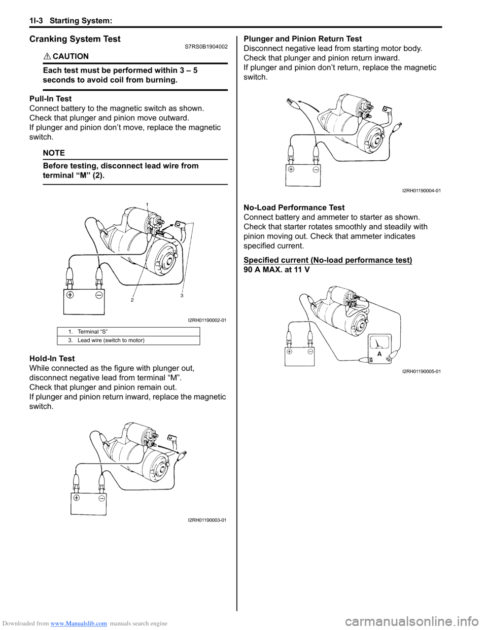
Cranking System TestS7RS0B1904002
CAUTION!
Each test must be performed within 3 – 5
seconds to avoid coil from burning.
Pull-In Test
Connect battery to the magnetic switch as shown.
Check that plunger and pinion move outward.
If plunger and pinion don’t move, replace the magnetic
switch.
NOTE
Before testing, disconnect lead wire from
terminal “M” (2).
Hold-In Test
While connected as the figure with plunger out,
disconnect negative lead from terminal “M”.
Check that plunger and pinion remain out.
If plunger and pinion return inward, replace the magnetic
switch. Plunger and Pinion Return Test
Disconnect negative lead from starting motor body.
Check that plunger and pinion return inward.
If plunger and pinion don’t return, replace the magnetic
switch.
No-Load Performance Test
Connect battery and ammeter to starter as shown.
Check that starter rotates
smoothly and steadily with
pinion moving out. Check that ammeter indicates
specified current.
Specified current (No-load performance test)
90 A MAX. at 11 V
1. Terminal “S”
3. Lead wire (switch to motor)
I2RH01190002-01
I2RH01190003-01
I2RH01190004-01
I2RH01190005-01
Page 415 of 1496
Downloaded from www.Manualslib.com manuals search engine Charging System: 1J-5
Generator Test (Undercharged Battery Check)S7RS0B1A04003
This condition, as evidenced by slow cranking or
indicator clear with dark or light yellow dot can be
caused by one or more of the following conditions even
though indicator lamp may be operating normal.
The following procedure also applies to cars with
voltmeter and ammeter.1) Make sure that undercharged condition has not been caused by accessories left on for extended period of
time.
2) Check drive belt for proper tension.
3) If battery defect is suspected, refer to “Battery Description”.
4) Inspect wiring for defects. Check all connections for tightness and cleanliness, battery cable connections
at battery, starting motor, ignition ground cable and
no “C” terminal circuit at ground.
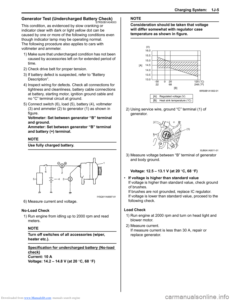
5) Connect switch (6), load (5), battery (4), voltmeter (3) and ammeter (2) to generator (1) as shown in
figure.
Voltmeter: Set between generator “B” terminal
and ground.
Ammeter: Set between generator “B” terminal
and battery (+) terminal.
NOTE
Use fully charged battery.
6) Measure current and voltage.
No-Load Check 1) Run engine from idling up to 2000 rpm and read meters.
NOTE
Turn off switches of all accessories (wiper,
heater etc.).
Specification for undercharged battery (No-load
check)
Current: 10 A
Voltage: 14.2 – 14.8 V (at 20 °C, 68 °F)
NOTE
Consideration should be taken that voltage
will differ somewhat with regulator case
temperature as shown in figure.
2) Using service wire, ground “C” terminal (1) of
generator.
3) Measure voltage between “B” terminal of generator and body ground.
Voltage: 12.5 – 13.1 V (at 20 °C, 68 °F)
• If voltage is higher than standard value
If voltage is higher than standard value, check ground
of brushes.
If brushes are not grounded, replace IC regulator.
If voltage is lower than standard value, proceed to the
following check.
Load Check 1) Run engine at 2000 rpm and turn on head light and blower motor.
2) Measure current. If measure current is less than 30 A, repair or
replace generator.
IYSQ011A0007-01
[A]: Regulated voltage (V)
[B]: Heat sink temperature ( °C)
16.0
15.5
15.0
14.5
14.0
13.5
13.0
-30 0 20
[A]
[B]
68
22120 (˚C)
248 (˚F)
(V)
I6RS0B1A1002-01
I5JB0A1A0011-01