Rear SUZUKI SWIFT 2006 2.G Service Workshop Manual
[x] Cancel search | Manufacturer: SUZUKI, Model Year: 2006, Model line: SWIFT, Model: SUZUKI SWIFT 2006 2.GPages: 1496, PDF Size: 34.44 MB
Page 759 of 1496
Downloaded from www.Manualslib.com manuals search engine Automatic Transmission/Transaxle: 5A-115
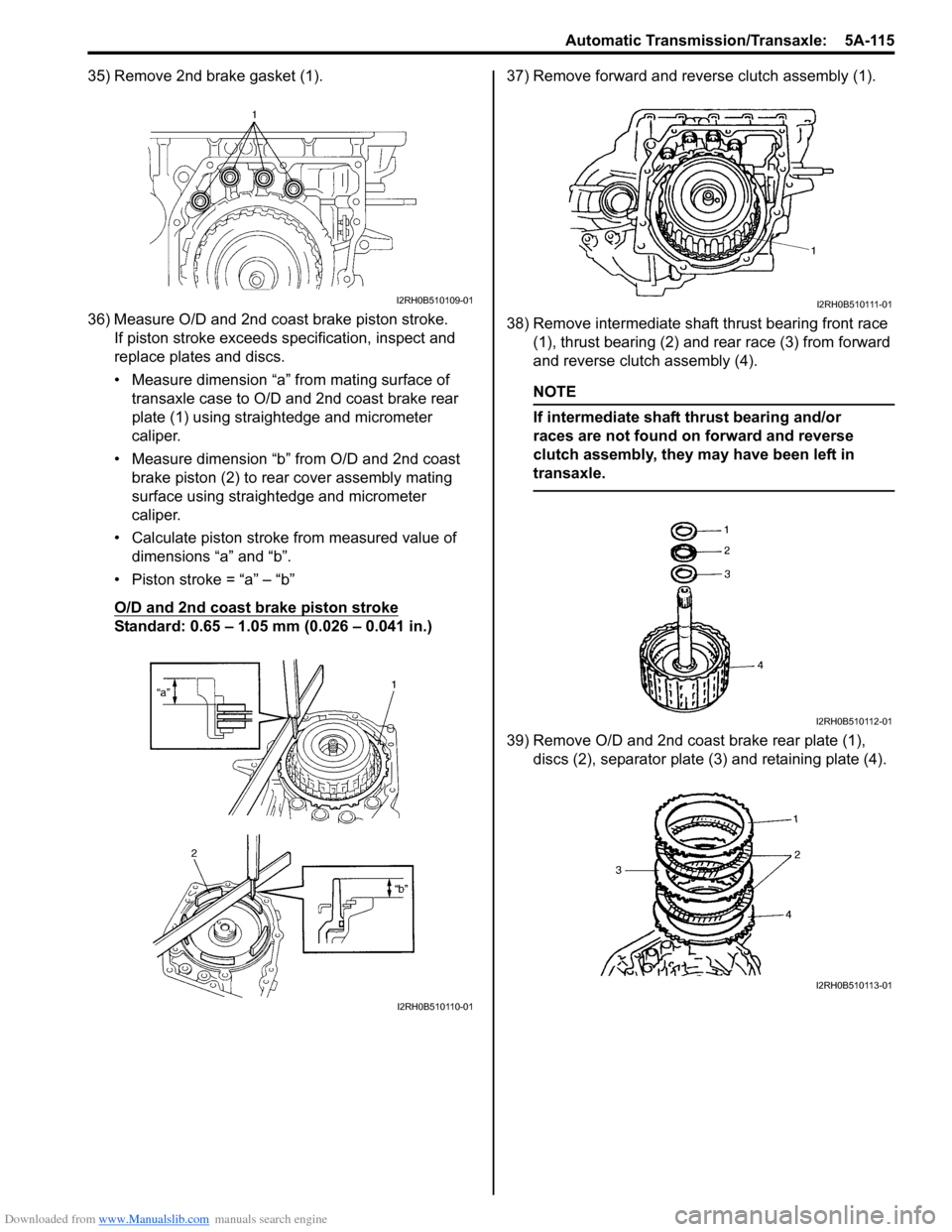
35) Remove 2nd brake gasket (1).
36) Measure O/D and 2nd coast brake piston stroke.If piston stroke exceeds specification, inspect and
replace plates and discs.
• Measure dimension “a” from mating surface of transaxle case to O/D and 2nd coast brake rear
plate (1) using straightedge and micrometer
caliper.
• Measure dimension “b” from O/D and 2nd coast brake piston (2) to rear cover assembly mating
surface using straightedge and micrometer
caliper.
• Calculate piston stroke from measured value of dimensions “a” and “b”.
• Piston stroke = “a” – “b”
O/D and 2nd coast brake piston stroke
Standard: 0.65 – 1.05 mm (0.026 – 0.041 in.) 37) Remove forward and reverse clutch assembly (1).
38) Remove intermediate shaft thrust bearing front race
(1), thrust bearing (2) and rear race (3) from forward
and reverse clutch assembly (4).
NOTE
If intermediate shaft thrust bearing and/or
races are not found on forward and reverse
clutch assembly, they may have been left in
transaxle.
39) Remove O/D and 2nd coast brake rear plate (1), discs (2), separator plate (3) and retaining plate (4).
I2RH0B510109-01
I2RH0B510110-01
I2RH0B510111-01
I2RH0B510112-01
I2RH0B510113-01
Page 760 of 1496
Downloaded from www.Manualslib.com manuals search engine 5A-116 Automatic Transmission/Transaxle:
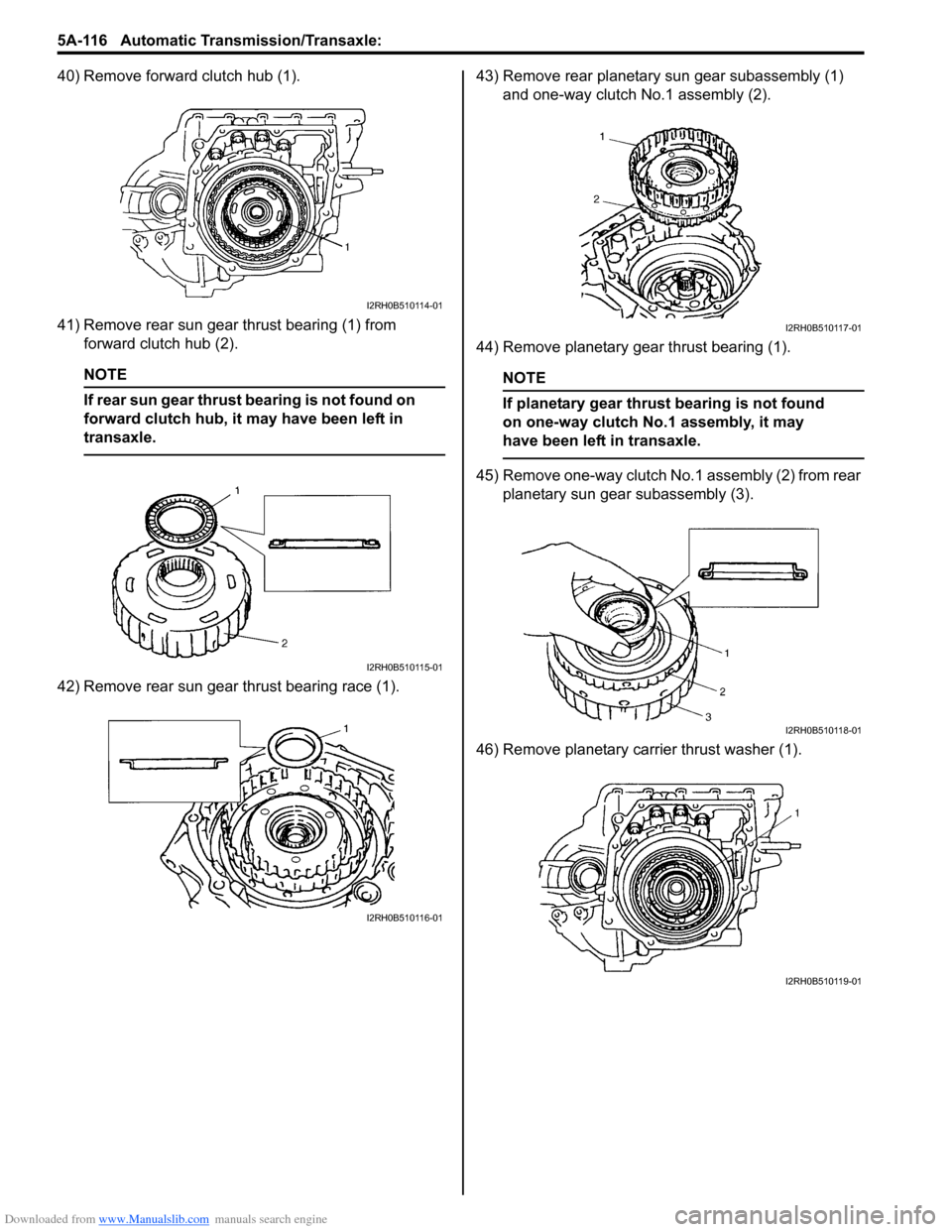
40) Remove forward clutch hub (1).
41) Remove rear sun gear thrust bearing (1) from forward clutch hub (2).
NOTE
If rear sun gear thrust bearing is not found on
forward clutch hub, it may have been left in
transaxle.
42) Remove rear sun gear thrust bearing race (1). 43) Remove rear planetary sun gear subassembly (1)
and one-way clutch No.1 assembly (2).
44) Remove planetary gear thrust bearing (1).
NOTE
If planetary gear thrust bearing is not found
on one-way clutch No.1 assembly, it may
have been left in transaxle.
45) Remove one-way clutch No.1 assembly (2) from rear planetary sun gear subassembly (3).
46) Remove planetary carrier thrust washer (1).
I2RH0B510114-01
I2RH0B510115-01
I2RH0B510116-01
I2RH0B510117-01
I2RH0B510118-01
I2RH0B510119-01
Page 773 of 1496
Downloaded from www.Manualslib.com manuals search engine Automatic Transmission/Transaxle: 5A-129
Forward and Reverse Clutch Assembly
Preliminary Check
S7RS0B5106042
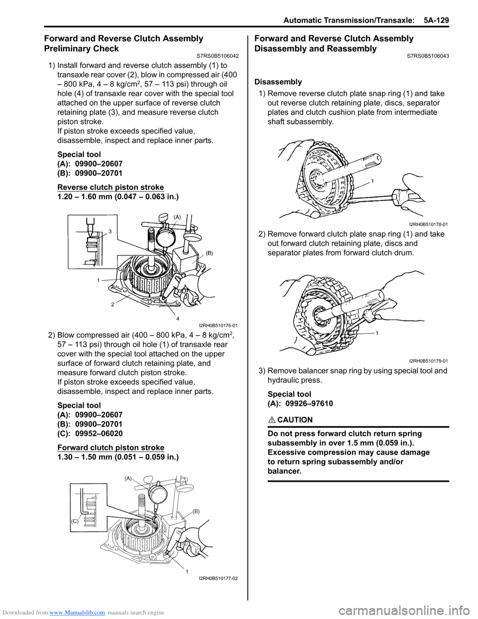
1) Install forward and reverse clutch assembly (1) to
transaxle rear cover (2), blow in compressed air (400
– 800 kPa, 4 – 8 kg/cm
2, 57 – 113 psi) through oil
hole (4) of transaxle rear cover with the special tool
attached on the upper surf ace of reverse clutch
retaining plate (3), and measure reverse clutch
piston stroke.
If piston stroke exce eds specified value,
disassemble, inspect and replace inner parts.
Special tool
(A): 09900–20607
(B): 09900–20701
Reverse clutch piston stroke
1.20 – 1.60 mm (0.047 – 0.063 in.)
2) Blow compressed air (400 – 800 kPa, 4 – 8 kg/cm
2,
57 – 113 psi) through oil hole (1) of transaxle rear
cover with the special tool attached on the upper
surface of forward clutch retaining plate, and
measure forward clutch piston stroke.
If piston stroke exce eds specified value,
disassemble, inspect and replace inner parts.
Special tool
(A): 09900–20607
(B): 09900–20701
(C): 09952–06020
Forward clutch piston stroke
1.30 – 1.50 mm (0.051 – 0.059 in.)
Forward and Reverse Clutch Assembly
Disassembly and Reassembly
S7RS0B5106043
Disassembly
1) Remove reverse clutch plate snap ring (1) and take out reverse clutch retaini ng plate, discs, separator
plates and clutch cushion plate from intermediate
shaft subassembly.
2) Remove forward clutch plate snap ring (1) and take out forward clutch retaining plate, discs and
separator plates from forward clutch drum.
3) Remove balancer snap ring by using special tool and hydraulic press.
Special tool
(A): 09926–97610
CAUTION!
Do not press forward clutch return spring
subassembly in over 1.5 mm (0.059 in.).
Excessive compression may cause damage
to return spring subassembly and/or
balancer.
I2RH0B510176-01
I2RH0B510177-02
I2RH0B510178-01
I2RH0B510179-01
Page 774 of 1496
Downloaded from www.Manualslib.com manuals search engine 5A-130 Automatic Transmission/Transaxle:
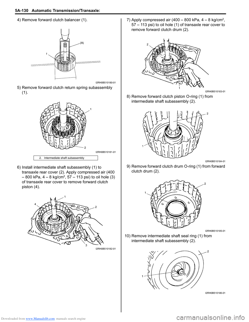
4) Remove forward clutch balancer (1).
5) Remove forward clutch return spring subassembly
(1).
6) Install intermed iate shaft subassembly (1) to
transaxle rear cover (2). Apply compressed air (400
– 800 kPa, 4 – 8 kg/cm
2, 57 – 113 psi) to oil hole (3)
of transaxle rear cover to remove forward clutch
piston (4). 7) Apply compressed air (400 – 800 kPa, 4 – 8 kg/cm
2,
57 – 113 psi) to oil hole (1) of transaxle rear cover to
remove forward clutch drum (2).
8) Remove forward clutch piston O-ring (1) from intermediate shaft subassembly (2).
9) Remove forward clutch drum O-ring (1) from forward clutch drum (2).
10) Remove intermediate shaft seal ring (1) from intermediate shaft subassembly (2).
2. Intermediate shaft subassembly
I2RH0B510180-01
I2RH0B510181-01
I2RH0B510182-01
I2RH0B510183-01
I2RH0B510184-01
I2RH0B510185-01
I2RH0B510186-01
Page 779 of 1496
Downloaded from www.Manualslib.com manuals search engine Automatic Transmission/Transaxle: 5A-135
Reassembly
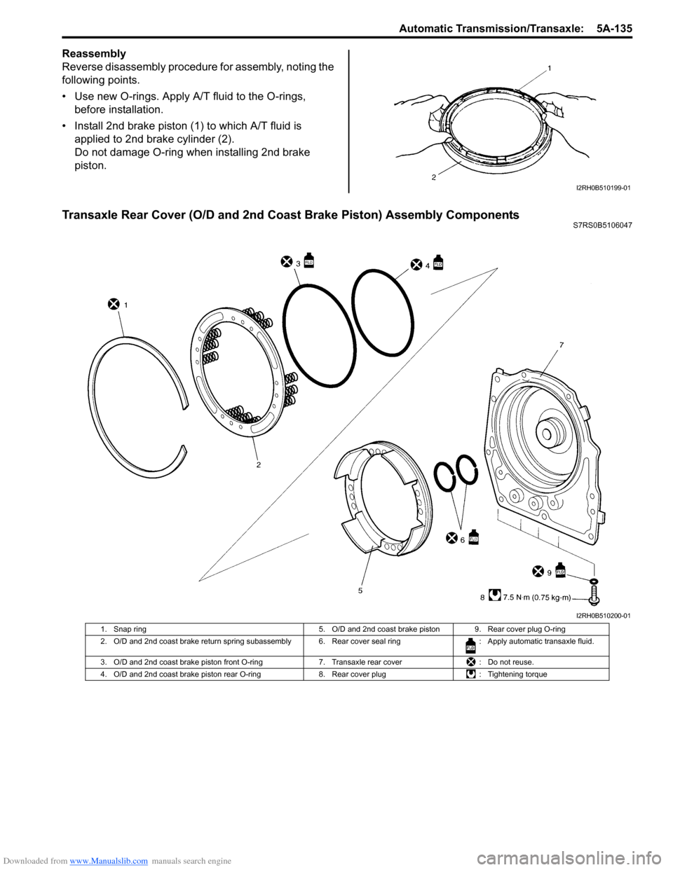
Reverse disassembly procedure for assembly, noting the
following points.
• Use new O-rings. Apply A/T fluid to the O-rings, before installation.
• Install 2nd brake piston (1) to which A/T fluid is applied to 2nd brake cylinder (2).
Do not damage O-ring wh en installing 2nd brake
piston.
Transaxle Rear Cover (O/D and 2nd Coast Brake Piston) Assembly ComponentsS7RS0B5106047
I2RH0B510199-01
I2RH0B510200-01
1. Snap ring 5. O/D and 2nd coast brake piston 9. Rear cover plug O-ring
2. O/D and 2nd coast brake return spring subassembly 6. R ear cover seal ring: Apply automatic transaxle fluid.
3. O/D and 2nd coast brake piston front O- ring7. Transaxle rear cover : Do not reuse.
4. O/D and 2nd coast brake piston rear O- ring8. Rear cover plug : Tightening torque
Page 780 of 1496
Downloaded from www.Manualslib.com manuals search engine 5A-136 Automatic Transmission/Transaxle:
Transaxle Rear Cover (O/D and 2nd Coast Brake
Piston) Assembly Disassembly and
Reassembly
S7RS0B5106048
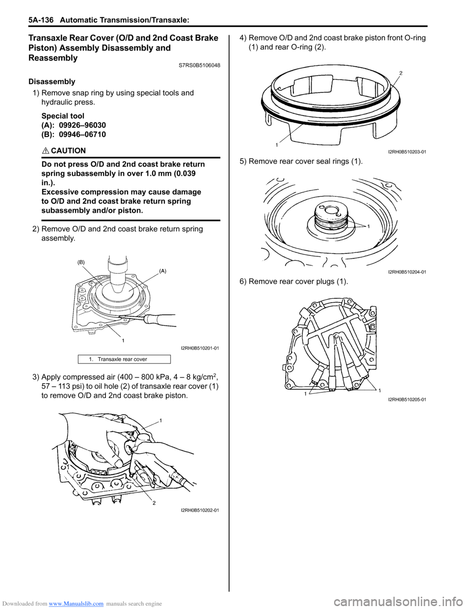
Disassembly1) Remove snap ring by using special tools and hydraulic press.
Special tool
(A): 09926–96030
(B): 09946–06710
CAUTION!
Do not press O/D and 2nd coast brake return
spring subassembly in over 1.0 mm (0.039
in.).
Excessive compression may cause damage
to O/D and 2nd coast brake return spring
subassembly and/or piston.
2) Remove O/D and 2nd coast brake return spring assembly.
3) Apply compressed air (400 – 800 kPa, 4 – 8 kg/cm
2,
57 – 113 psi) to oil hole (2) of transaxle rear cover (1)
to remove O/D and 2nd coast brake piston. 4) Remove O/D and 2nd coast brake piston front O-ring
(1) and rear O-ring (2).
5) Remove rear cove r seal rings (1).
6) Remove rear cover plugs (1).
1. Transaxle rear cover
I2RH0B510201-01
I2RH0B510202-01
I2RH0B510203-01
I2RH0B510204-01
I2RH0B510205-01
Page 781 of 1496
Downloaded from www.Manualslib.com manuals search engine Automatic Transmission/Transaxle: 5A-137
Reassembly
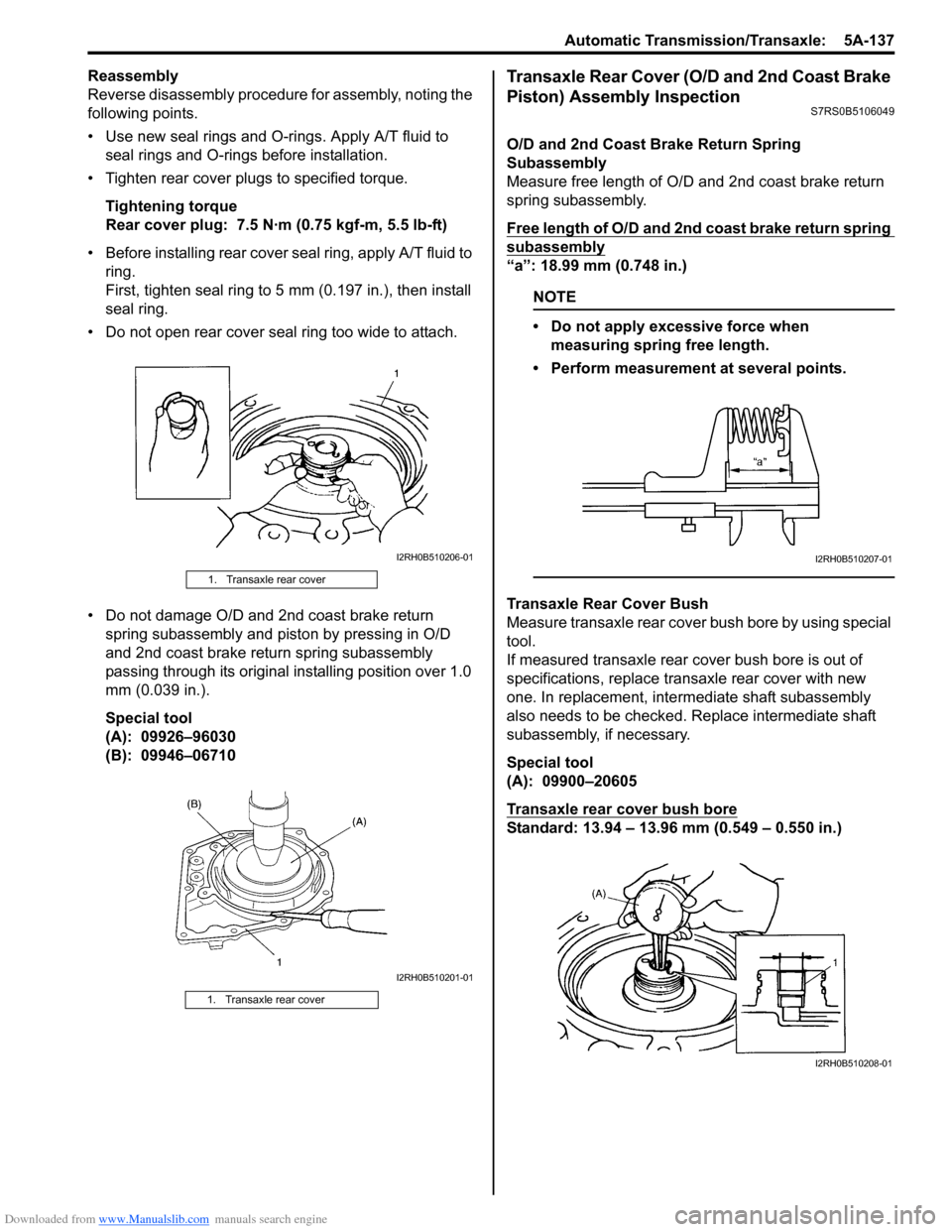
Reverse disassembly procedure for assembly, noting the
following points.
• Use new seal rings and O-rings. Apply A/T fluid to seal rings and O-rings before installation.
• Tighten rear cover plugs to specified torque.
Tightening torque
Rear cover plug: 7.5 N·m (0.75 kgf-m, 5.5 lb-ft)
• Before installing rear cover seal ring, apply A/T fluid to ring.
First, tighten seal ring to 5 mm (0.197 in.), then install
seal ring.
• Do not open rear cover seal ring too wide to attach.
• Do not damage O/D and 2nd coast brake return spring subassembly and piston by pressing in O/D
and 2nd coast brake return spring subassembly
passing through its original installing position over 1.0
mm (0.039 in.).
Special tool
(A): 09926–96030
(B): 09946–06710Transaxle Rear Cover (O/D and 2nd Coast Brake
Piston) Assembly Inspection
S7RS0B5106049
O/D and 2nd Coast Brake Return Spring
Subassembly
Measure free length of O/D and 2nd coast brake return
spring subassembly.
Free length of O/D and 2nd coast brake return spring
subassembly
“a”: 18.99 mm (0.748 in.)
NOTE
• Do not apply excessive force when measuring spring free length.
• Perform measurement at several points.
Transaxle Rear Cover Bush
Measure transaxle rear cover bush bore by using special
tool.
If measured transaxle rear cover bush bore is out of
specifications, replace transaxle rear cover with new
one. In replacement, inte rmediate shaft subassembly
also needs to be checked. Replace intermediate shaft
subassembly, if necessary.
Special tool
(A): 09900–20605
Transaxle rear cover bush bore
Standard: 13.94 – 13.96 mm (0.549 – 0.550 in.)
1. Transaxle rear cover
1. Transaxle rear cover
I2RH0B510206-01
I2RH0B510201-01
I2RH0B510207-01
I2RH0B510208-01
Page 792 of 1496
Downloaded from www.Manualslib.com manuals search engine 5A-148 Automatic Transmission/Transaxle:
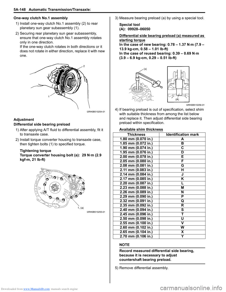
One-way clutch No.1 assembly1) Install one-way clutch No.1 assembly (2) to rear planetary sun gear subassembly (1).
2) Securing rear planetary sun gear subassembly, ensure that one-way clutch No.1 assembly rotates
only in one direction.
If the one-way clutch rotates in both directions or it
does not rotate in either direction, replace it with new
one.
Adjustment
Differential side bearing preload 1) After applying A/T fluid to differential assembly, fit it to transaxle case.
2) Install torque converter housing to transaxle case, then tighten bolts (1) to specified torque.
Tightening torque
Torque converter housing bolt (a): 29 N·m (2.9
kgf-m, 21 lb-ft) 3) Measure bearing preload (a) by using a special tool.
Special tool
(A): 09928–06050
Differential side bearing preload (a) measured as
starting torque
In the case of new bearing: 0.78 – 1.37 N ⋅m (7.9 –
13.9 kg-cm, 0.58 – 1.01 lb-ft)
In the case of reused bearing: 0.39 – 0.69 N ⋅m
(3.9 – 6.9 kg-cm, 0.29 – 0.51 lb-ft)
4) If bearing preload is out of specification, select shim with suitable thickness from among the list below
and replace it. Then adjust differential side bearing
preload within specification.
Available shim thickness
NOTE
Record measured differential side bearing,
because it is necessary to adjust
countershaft bearing preload.
5) Remove differential assembly.
I2RH0B510254-01
I2RH0B510255-01
Thickness Identification mark
1.80 mm (0.070 in.) A
1.85 mm (0.072 in.) B
1.90 mm (0.074 in.) C
1.95 mm (0.076 in.) D
2.00 mm (0.078 in.) E
2.05 mm (0.080 in.) F
2.08 mm (0.081 in.) G
2.11 mm (0.083 in.) H
2.14 mm (0.084 in.) J
2.17 mm (0.085 in.) K
2.20 mm (0.087 in.) L
2.23 mm (0.088 in.) M
2.26 mm (0.089 in.) N
2.29 mm (0.090 in.) P
2.32 mm (0.091 in.) Q
2.35 mm (0.092 in.) R
2.40 mm (0.094 in.) S
2.45 mm (0.096 in.) T
2.50 mm (0.098 in.) U
2.55 mm (0.100 in.) V
2.60 mm (0.102 in.) W
2.65 mm (0.104 in.) X
2.70 mm (0.106 in.) Y
I2RH0B510256-01
Page 800 of 1496
Downloaded from www.Manualslib.com manuals search engine 5A-156 Automatic Transmission/Transaxle:
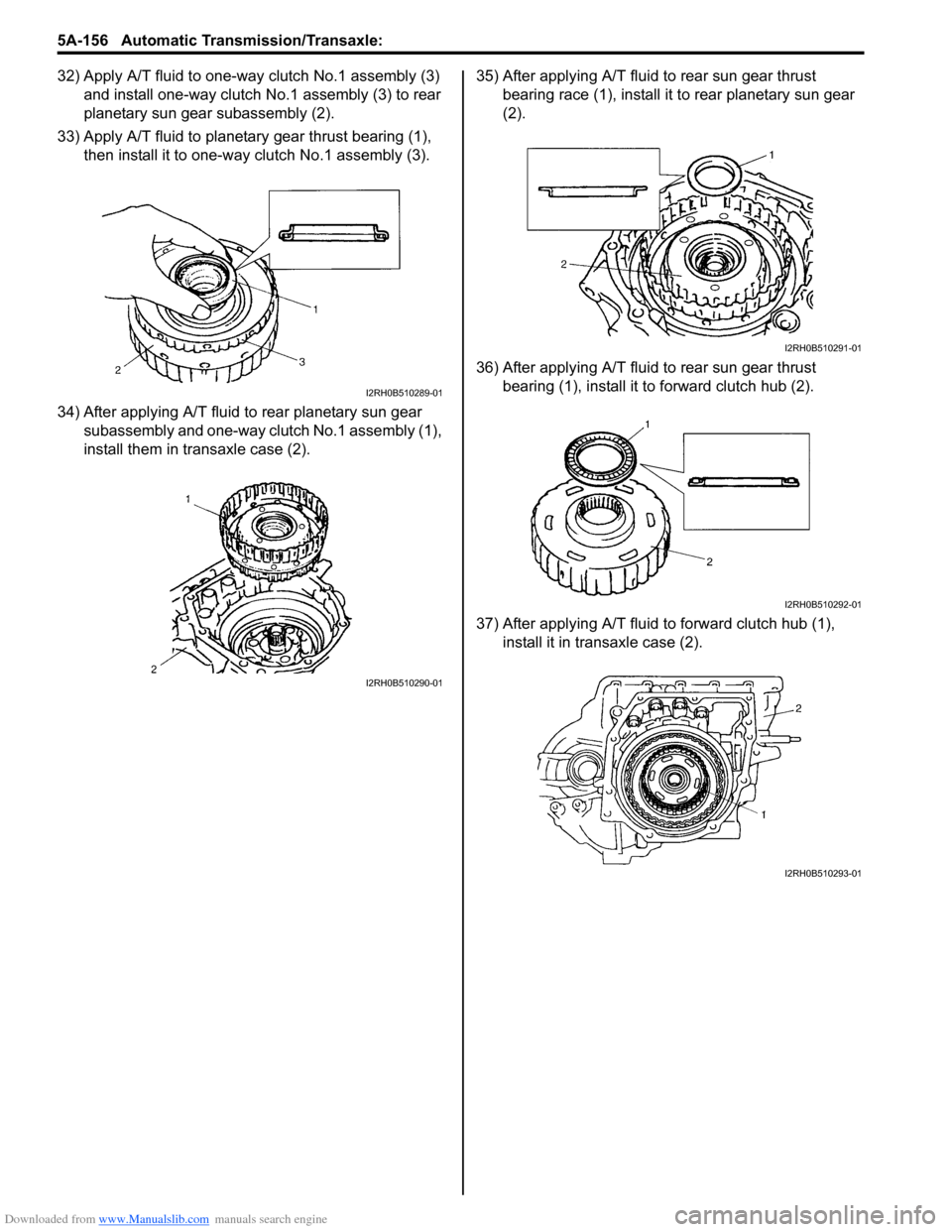
32) Apply A/T fluid to one-way clutch No.1 assembly (3) and install one-way clutch No .1 assembly (3) to rear
planetary sun gear subassembly (2).
33) Apply A/T fluid to planetary gear thrust bearing (1), then install it to one-way clutch No.1 assembly (3).
34) After applying A/T fluid to rear planetary sun gear subassembly and one-way clutch No.1 assembly (1),
install them in transaxle case (2). 35) After applying A/T fluid to rear sun gear thrust
bearing race (1), install it to rear planetary sun gear
(2).
36) After applying A/T fluid to rear sun gear thrust bearing (1), install it to forward clutch hub (2).
37) After applying A/T fluid to forward clutch hub (1), install it in transaxle case (2).
I2RH0B510289-01
I2RH0B510290-01
I2RH0B510291-01
I2RH0B510292-01
I2RH0B510293-01
Page 801 of 1496
Downloaded from www.Manualslib.com manuals search engine Automatic Transmission/Transaxle: 5A-157
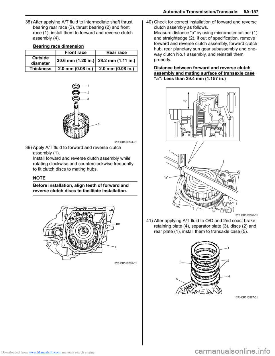
38) After applying A/T fluid to intermediate shaft thrust bearing rear race (3), thrust bearing (2) and front
race (1), install them to forward and reverse clutch
assembly (4).
Bearing race dimension
39) Apply A/T fluid to forward and reverse clutch assembly (1).
Install forward and revers e clutch assembly while
rotating clockwise and co unterclockwise frequently
to fit clutch discs to mating hubs.
NOTE
Before installation, align teeth of forward and
reverse clutch discs to facilitate installation.
40) Check for correct installation of forward and reverse clutch assembly as follows.
Measure distance “a” by using micrometer caliper (1)
and straightedge (2). If out of specification, remove
forward and reverse clutch assembly, forward clutch
hub, rear planetary sun gear subassembly and one-
way clutch No.1 assemb ly, and reinstall them
properly.
Distance between forward and reverse clutch
assembly and mating surface of transaxle case
“a”: Less than 29.4 mm (1.157 in.)
41) After applying A/T fluid to O/D and 2nd coast brake retaining plate (4), separator plate (3), discs (2) and
rear plate (1), install th em to transaxle case (5).
Front race Rear race
Outside
diameter 30.6 mm (1.20 in.) 28.2 mm (1.11 in.)
Thickness 2.0 mm (0.08 in.) 2.0 mm (0.08 in.)
I2RH0B510294-01
I2RH0B510295-01
“a”
“a”
1 2
I2RH0B510296-01
I2RH0B510297-01