Shift SUZUKI SWIFT 2006 2.G Service Workshop Manual
[x] Cancel search | Manufacturer: SUZUKI, Model Year: 2006, Model line: SWIFT, Model: SUZUKI SWIFT 2006 2.GPages: 1496, PDF Size: 34.44 MB
Page 1226 of 1496
Downloaded from www.Manualslib.com manuals search engine 9A-55 Wiring Systems:
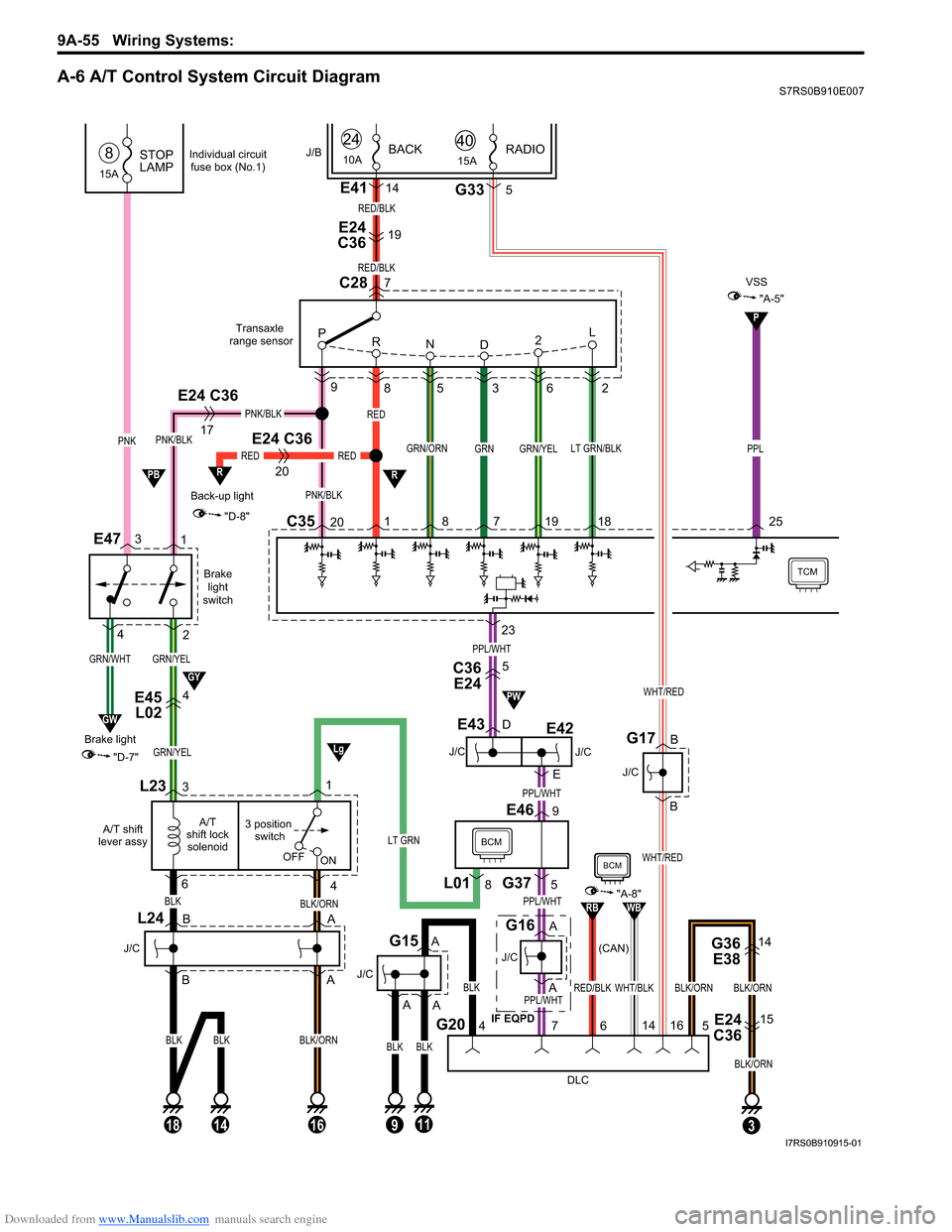
A-6 A/T Control System Circuit DiagramS7RS0B910E007
GRN/YEL
Brakelight
switch
E47
GRN/YEL
C3520 8 7 19 18
9
85 3 6 2
GRN/YEL
Back-up light
20
RED
"D-8"
R
Transaxle
range sensor
TCM
L23
4
3 position switch
A/T
shift lock solenoid
A/T shift
lever assy
BLK/ORN
16
OFF ON
RED
1
RED
BLK
PNK/BLK
GRN/ORNLT GRN/BLK
C28
P
R ND 2L
PNK/BLK
1
2
E24 C36
17
PNK/BLK
BLK
63
BLK/ORN
18
BLK
14
L24
J/C
E45
L024
J/C
E43
J/C (CAN)
G16
BCM
DLC
G207
G375
E469
4
BLK
BLKBLK
11
J/C
G15
3
G36
E3814
E24
C3615
BLK/ORNBLK/ORN
5
23
GRN
RED/BLK
7
E24
C3619
E4114
RED/BLK
PNK
15A
STOP
LAMP8
GRN/WHT
GW
"D-7"
Brake light
3
4
J/B
L018
1
24
10ABACK
A
A
B
B A
A
PPL/WHT
PPL/WHT
PPL/WHT
PPL/WHT
A
A
D
E
LT GRN
P
"A-5"
VSS
PPL
25
R
C36E245
Lg
GY
PB
PW
9
A
Individual circuit
fuse box (No.1)
WHT/BLKRED/BLK
RBWB
BCM
"A-8"
14
6
BLK/ORN
15ARADIO40
G335
WHT/RED
B
B
J/C
G17
WHT/RED
16
J/C
E42
IF EQPD
E24 C36
I7RS0B910915-01
Page 1227 of 1496
Downloaded from www.Manualslib.com manuals search engine Wiring Systems: 9A-56
ORN
TCM
Lock up
solenoidA/T fluid
temperature sensorShift
solenoid No.2 Shift
solenoid No.1
11
12
C291
6
BLK/YEL
3
2
BRN
10
15
4
2
14
5
4
9
Timing
solenoid
WHT/BLKGRYWHT/BLU
Pressure control
solenoid
LT GRN/BLK
3
8
Shift solenoid
LT GRNBLU/BLK
5
ECM
WHTREDWHT/RED
WHT/RED
E24
C3618
C37
BLK
BLKBLK
E394
WHT/RED
24 C34717
23 116
12
13
E232
J/B
15ARADIO
40
15A
AT
ETM
7
6
LT GRN/BLK
WHTBLK
6 16
2
1C27
Input shaft
speed sensor
C35
C34
E33
5 2
3
1
YEL/BLU
10AIG1 SIG
29
E4112
E
E
J/C
(CAN)
E43
BLK
BLK
A/T relay
YEL/BLK
54
E24
C366
YEL/BLK
Individual circuit
fuse box (No.1)
I7RS0B910916-01
Page 1230 of 1496
Downloaded from www.Manualslib.com manuals search engine 9A-59 Wiring Systems:
9
15 7
"D-5"
"A-6"
A/T
GRY/RED
RED/BLU
16
A A
B
BG37
BLU/YEL
BLU/YEL
J/C
G17
J/C
G17
G22
G22
1
4
Main switch
(Key switch)
RADIO
G335
15A
40
WHT/RED
WHT/RED
YEL/RED
YEL/BLK1E14
2
Outside air
temperature sensor
"B-5"
Switch
6L0114
1617125
RED/BLKBRN/YEL
LT GRN/BLK
BRN
GRY/WHT
GRY
Parking
brake
switch
Seat
belt
switch
"C-3"
"D-1"
RBBY
8
LT GRN
A/T shift lever A/T shift
lever
115
"D-4"
LgRB
GR
Oil
pressure switchBrakefluid
level
switch
B
DRL
controller
B
E46
10E468
LgBBGWG
Main switch
"B-5"
Front door switch
Front door switch
Rear door switch
"D-5"
"D-5"
BRBR
BLK/RED
J/B
BCM
BLURED/BLK
RB
Other than indonesian make
Indonesian make
A
AB
B
I7RS0B910942-01
Page 1252 of 1496
Downloaded from www.Manualslib.com manuals search engine 9A-81 Wiring Systems:
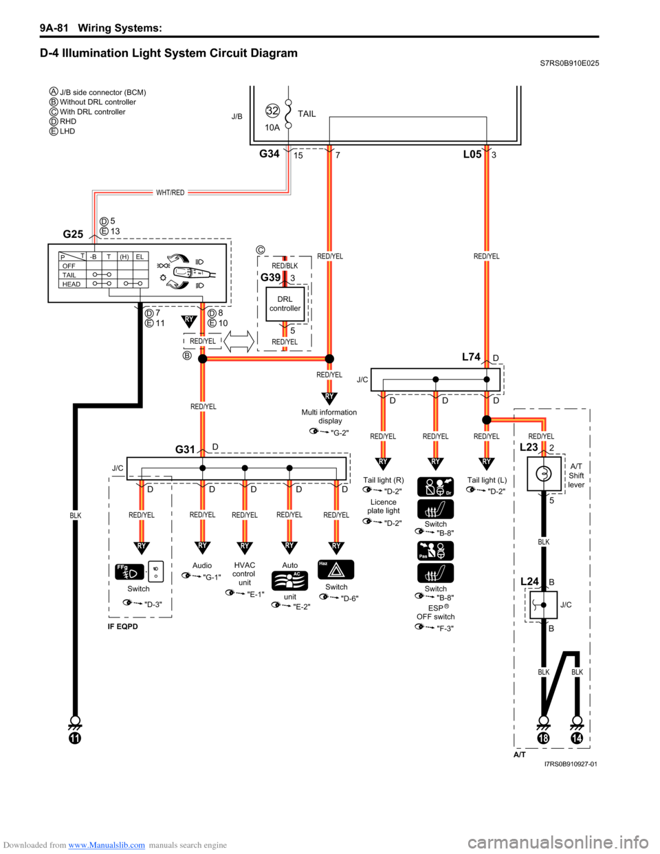
D-4 Illumination Light System Circuit DiagramS7RS0B910E025
WHT/RED
A/T
Shift
lever
L23
L742
5
BLK
BLKBLK
10A
TAIL
32J/B
15G34
BLK
G25
111814
A/T
B
B
J/C
L24
RED/YEL
RED/YEL
L053
"D-3"
IF EQPD
RY
Switch
J/C J/C
G31
RED/YEL
RY
RED/YEL
Switch
RY
RED/YEL
HVAC
control unit Auto
unit
"E-1"
"E-2""D-6"
OFF
TAIL
HEAD -BT
T
P(H) ELRED/YEL
7
RY
RED/YEL
Audio
"G-1"
D
D
D
D
D
D
D
RY
RED/YEL
D
D
RY
RY
RED/YEL
Multi information
display
"G-2"RED/YEL
RED/YEL
RED/YEL
RY
Tail light (L) "D-2"
RED/YEL
RY
Tail light (R) "D-2"
Licence
plate light
"D-2"
J/B side connector (BCM)
Without DRL controller
With DRL controller
RHD
LHD
A
R
BCDE
Switch
"B-8"
Switch"B-8"
ESP
OFF switch
"F-3"
DE5
13
DE7
11DE
B
C
8
10
DRL
controller
G393
5
RED/YEL
RED/BLK
RED/YEL
D
RY
I7RS0B910927-01
Page 1256 of 1496
Downloaded from www.Manualslib.com manuals search engine 9A-85 Wiring Systems:
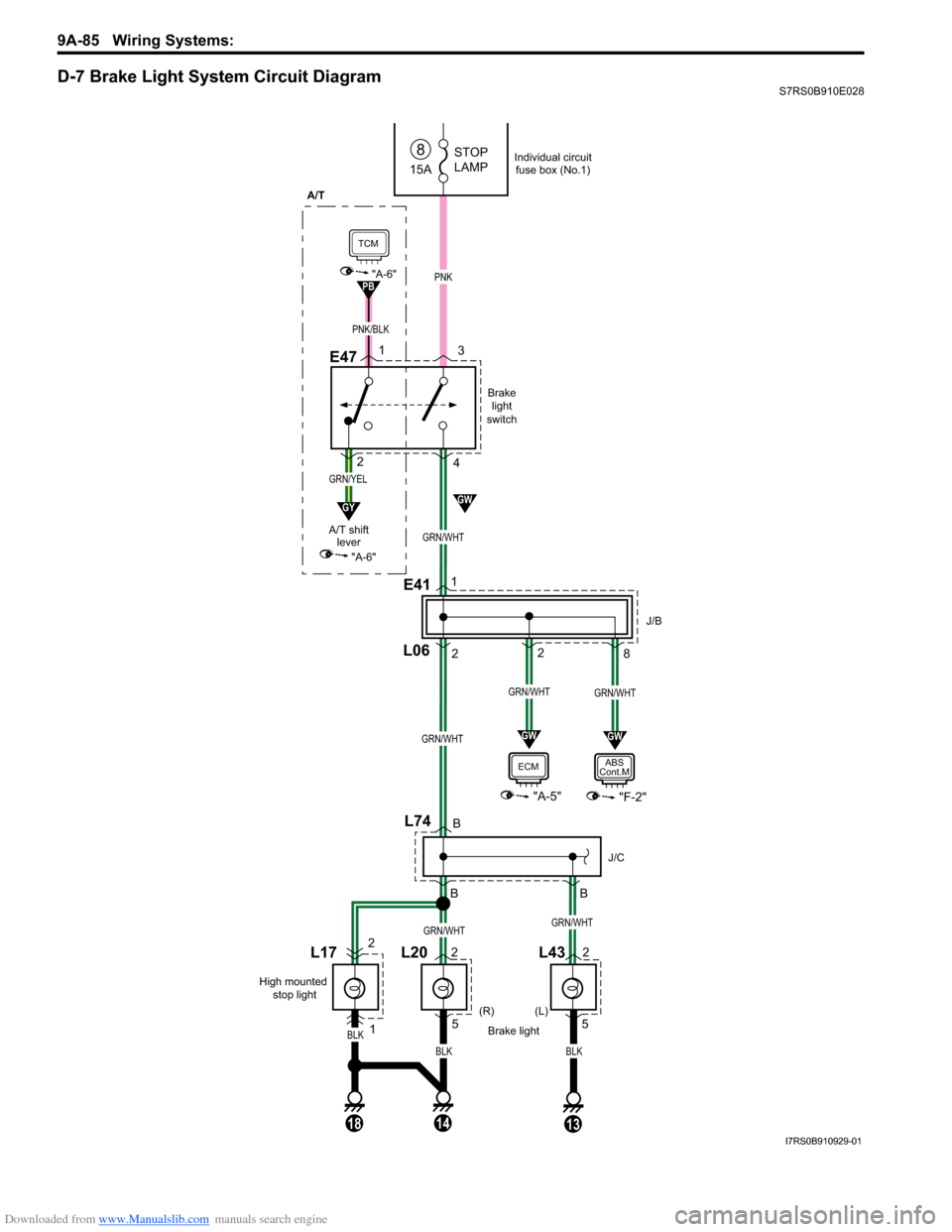
D-7 Brake Light System Circuit DiagramS7RS0B910E028
Brakelight
switch
(R)
Brake light
PNK
BLK
(L)
15A
8STOP
LAMP
E47
L43
GRN/WHT
GRN/WHT
GRN/WHT
5
4
1
L0628
E411
J/B
"F-2"
ABS
Cont.M
GRN/WHT
2
"A-5"
ECM
13
GW
GWGW
TCM
PB
PNK/BLK
"A-6"
GRN/YEL
A/T shift
lever
GY
"A-6"
2 3
A/T
18
Individual circuit
fuse box (No.1)
B
BL74
J/C
L202
5L172
1
High mounted stop light
14
BLK
BLK
2
B
GRN/WHTGRN/WHT
I7RS0B910929-01
Page 1286 of 1496
Downloaded from www.Manualslib.com manuals search engine 9B-4 Lighting Systems:
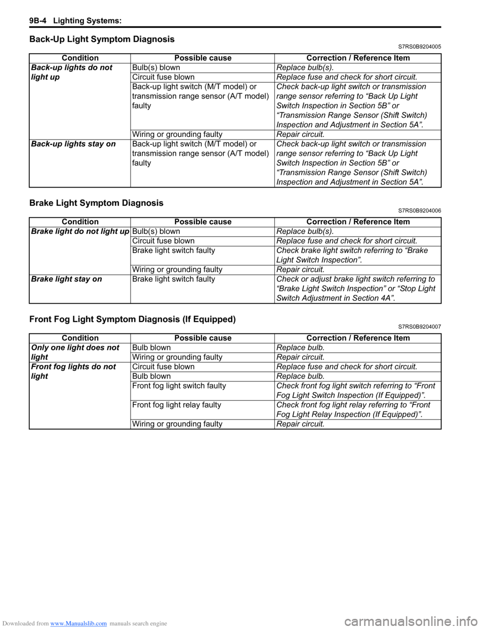
Back-Up Light Symptom DiagnosisS7RS0B9204005
Brake Light Symptom DiagnosisS7RS0B9204006
Front Fog Light Symptom Diagnosis (If Equipped)S7RS0B9204007
ConditionPossible cause Correction / Reference Item
Back-up lights do not
light up Bulb(s) blown
Replace bulb(s).
Circuit fuse blown Replace fuse and check for short circuit.
Back-up light switch (M/T model) or
transmission range sensor (A/T model)
faulty Check back-up light switch or transmission
range sensor referring to “Back Up Light
Switch Inspection in Section 5B” or
“Transmission Range Sensor (Shift Switch)
Inspection and Adjustment in Section 5A”.
Wiring or grounding faulty Repair circuit.
Back-up lights stay on Back-up light switch (M/T model) or
transmission range sensor (A/T model)
faulty Check back-up light switch or transmission
range sensor referring to “Back Up Light
Switch Inspection in Section 5B” or
“Transmission Range Sensor (Shift Switch)
Inspection and Adjustment in Section 5A”.
Condition
Possible cause Correction / Reference Item
Brake light do not light up Bulb(s) blown Replace bulb(s).
Circuit fuse blown Replace fuse and check for short circuit.
Brake light switch faulty Check brake light switch referring to “Brake
Light Switch Inspection”.
Wiring or grounding faulty Repair circuit.
Brake light stay on Brake light switch faulty Check or adjust brake light switch referring to
“Brake Light Switch Inspection” or “Stop Light
Switch Adjustment in Section 4A”.
ConditionPossible cause Correction / Reference Item
Only one light does not
light Bulb blown
Replace bulb.
Wiring or grounding faulty Repair circuit.
Front fog lights do not
light Circuit fuse blown
Replace fuse and check for short circuit.
Bulb blown Replace bulb.
Front fog light switch faulty Check front fog light switch referring to “Front
Fog Light Switch Inspection (If Equipped)”.
Front fog light relay faulty Check front fog light relay referring to “Front
Fog Light Relay Inspection (If Equipped)”.
Wiring or grounding faulty Repair circuit.
Page 1299 of 1496
Downloaded from www.Manualslib.com manuals search engine Instrumentation / Driver Info. / Horn: 9C-4
Schematic and Routing Diagram
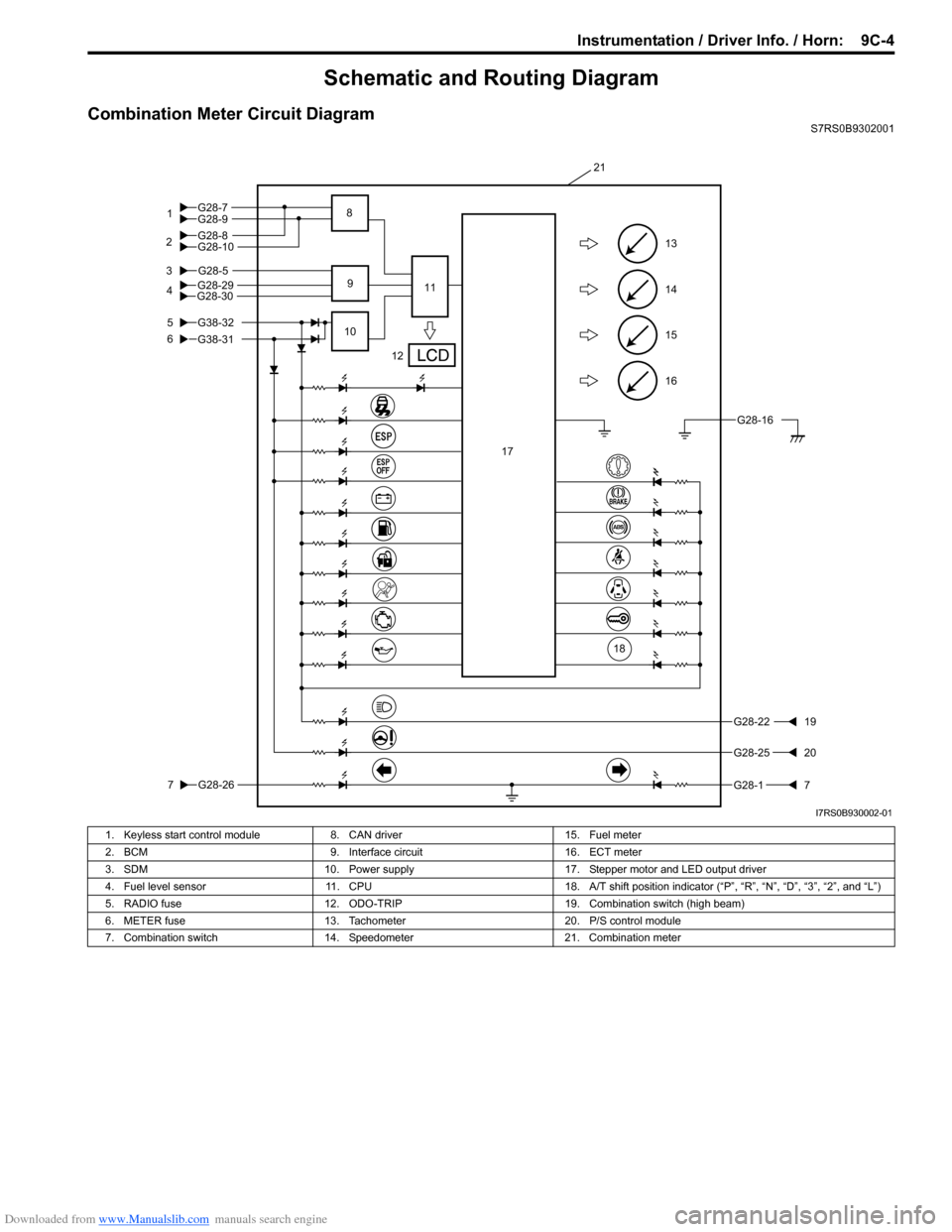
Combination Meter Circuit DiagramS7RS0B9302001
16
15
14
13
G28-5
5
6
3
G28-26
7
G28-2219
G28-2520
G28-17
12
10 11
21
9
17
G28-304G28-29
18
G28-16
G28-9
G28-10G28-8 G28-7
1
2 8
G38-31
G38-32
I7RS0B930002-01
1. Keyless start control module
8. CAN driver 15. Fuel meter
2. BCM 9. Interface circuit 16. ECT meter
3. SDM 10. Power supply 17. Stepper motor and LED output driver
4. Fuel level sensor 11. CPU 18. A/T shift position indicator (“P”, “R”, “N”, “D”, “3”, “2”, and “L”)
5. RADIO fuse 12. ODO-TRIP 19. Combination switch (high beam)
6. METER fuse 13. Tachometer 20. P/S control module
7. Combination switch 14. Speedometer 21. Combination meter
Page 1304 of 1496
Downloaded from www.Manualslib.com manuals search engine 9C-9 Instrumentation / Driver Info. / Horn:
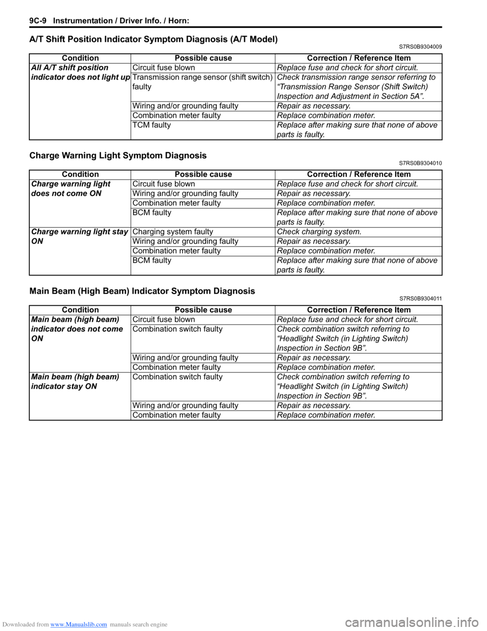
A/T Shift Position Indicator Symptom Diagnosis (A/T Model)S7RS0B9304009
Charge Warning Light Symptom DiagnosisS7RS0B9304010
Main Beam (High Beam) Indicator Symptom DiagnosisS7RS0B9304011
ConditionPossible cause Correction / Reference Item
All A/T shift position
indicator does not light up Circuit fuse blown
Replace fuse and check for short circuit.
Transmission range sens or (shift switch)
faulty Check transmission range sensor referring to
“Transmission Range Sensor (Shift Switch)
Inspection and Adjustment in Section 5A”.
Wiring and/or grounding faulty Repair as necessary.
Combination meter faulty Replace combination meter.
TCM faulty Replace after making sure that none of above
parts is faulty.
ConditionPossible cause Correction / Reference Item
Charge warning light
does not come ON Circuit fuse blown
Replace fuse and check for short circuit.
Wiring and/or grounding faulty Repair as necessary.
Combination meter faulty Replace combination meter.
BCM faulty Replace after making sure that none of above
parts is faulty.
Charge warning light stay
ON Charging system faulty
Check charging system.
Wiring and/or grounding faulty Repair as necessary.
Combination meter faulty Replace combination meter.
BCM faulty Replace after making sure that none of above
parts is faulty.
ConditionPossible cause Correction / Reference Item
Main beam (high beam)
indicator does not come
ON Circuit fuse blown
Replace fuse and check for short circuit.
Combination switch faulty Check combination switch referring to
“Headlight Switch (in Lighting Switch)
Inspection in Section 9B”.
Wiring and/or grounding faulty Repair as necessary.
Combination meter faulty Replace combination meter.
Main beam (high beam)
indicator stay ON Combination switch faulty
Check combination switch referring to
“Headlight Switch (in Lighting Switch)
Inspection in Section 9B”.
Wiring and/or grounding faulty Repair as necessary.
Combination meter faulty Replace combination meter.