body control SUZUKI SWIFT 2006 2.G Service Workshop Manual
[x] Cancel search | Manufacturer: SUZUKI, Model Year: 2006, Model line: SWIFT, Model: SUZUKI SWIFT 2006 2.GPages: 1496, PDF Size: 34.44 MB
Page 719 of 1496
Downloaded from www.Manualslib.com manuals search engine Automatic Transmission/Transaxle: 5A-75
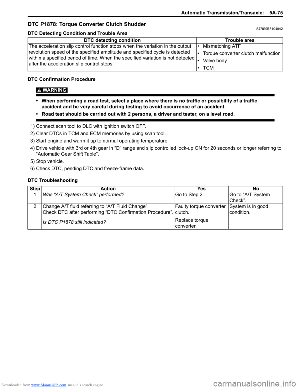
DTC P1878: Torque Converter Clutch ShudderS7RS0B5104042
DTC Detecting Condition and Trouble Area
DTC Confirmation Procedure
WARNING!
• When performing a road test, select a place where there is no traffic or possibility of a traffic accident and be very careful during testing to avoid occurrence of an accident.
• Road test should be carried out with 2 persons, a driver and tester, on a level road.
1) Connect scan tool to DLC with ignition switch OFF.
2) Clear DTCs in TCM and ECM memories by using scan tool.
3) Start engine and warm it up to normal operating temperature.
4) Drive vehicle with 3rd or 4th gear in “D” range and slip c ontrolled lock-up ON for 20 seconds or longer referring to
“Automatic Gear Shift Table”.
5) Stop vehicle.
6) Check DTC, pending DTC and freeze-frame data.
DTC Troubleshooting DTC detecting condition
Trouble area
The acceleration slip control function stops when the variation in the output
revolution speed of the specified amp litude and specified cycle is detected
within a specified period of time. When t he specified variation is not detected
after the acceleration slip control stops. • Mismatching ATF
• Torque converter clutch malfunction
• Valve body
•TCM
Step
Action YesNo
1 Was “A/T System Check” performed? Go to Step 2.Go to “A/T System
Check”.
2 Change A/T fluid referring to “A/T Fluid Change”. Check DTC after performing “DTC Confirmation Procedure”.
Is DTC P1878 still indicated? Faulty torque converter
clutch.
Replace torque
converter.System is in good
condition.
Page 721 of 1496
Downloaded from www.Manualslib.com manuals search engine Automatic Transmission/Transaxle: 5A-77
DTC TroubleshootingStep Action Yes No 1 Was “A/T System Check” performed? Go to Step 2. Go to “A/T System
Check”.
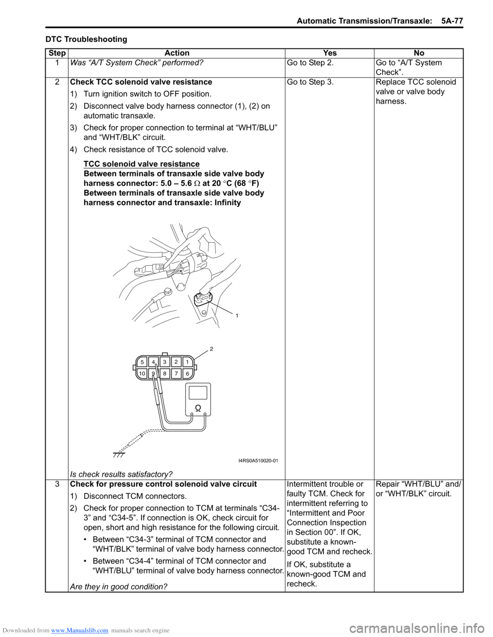
2 Check TCC solenoid valve resistance
1) Turn ignition switch to OFF position.
2) Disconnect valve body harness connector (1), (2) on
automatic transaxle.
3) Check for proper connection to terminal at “WHT/BLU” and “WHT/BLK” circuit.
4) Check resistance of TCC solenoid valve.
TCC solenoid valve resistance
Between terminals of transaxle side valve body
harness connector: 5.0 – 5.6 Ω at 20 °C (68 °F)
Between terminals of transaxle side valve body
harness connector and transaxle: Infinity
Is check results satisfactory? Go to Step 3. Replace TCC solenoid
valve or valve body
harness.
3 Check for pressure control solenoid valve circuit
1) Disconnect TCM connectors.
2) Check for proper connection to TCM at terminals “C34-
3” and “C34-5”. If connection is OK, check circuit for
open, short and high resistance for the following circuit.
• Between “C34-3” terminal of TCM connector and “WHT/BLK” terminal of valve body harness connector.
• Between “C34-4” terminal of TCM connector and “WHT/BLU” terminal of valve body harness connector.
Are they in good condition? Intermittent trouble or
faulty TCM. Check for
intermittent referring to
“Intermittent and Poor
Connection Inspection
in Section 00”. If OK,
substitute a known-
good TCM and recheck.
If OK, substitute a
known-good TCM and
recheck.
Repair “WHT/BLU” and/
or “WHT/BLK” circuit.
1
6
7
89
10 5
43 2
1
2
I4RS0A510020-01
Page 723 of 1496
Downloaded from www.Manualslib.com manuals search engine Automatic Transmission/Transaxle: 5A-79
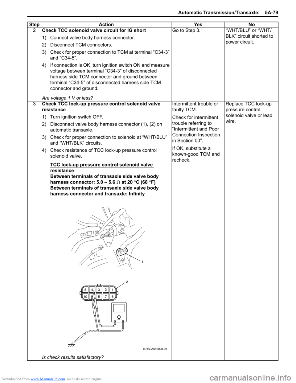
2Check TCC solenoid valve circuit for IG short
1) Connect valve body harness connector.
2) Disconnect TCM connectors.
3) Check for proper connection to TCM at terminal “C34-3”
and “C34-5”.
4) If connection is OK, turn ignition switch ON and measure voltage between terminal “C34-3” of disconnected
harness side TCM connector and ground between
terminal “C34-5” of disconnected harness side TCM
connector and ground.
Are voltage 1 V or less? Go to Step 3. “WHT/BLU” or “WHT/
BLK” circuit shorted to
power circuit.
3 Check TCC lock-up pressure control solenoid valve
resistance
1) Turn ignition switch OFF.
2) Disconnect valve body harness connector (1), (2) on
automatic transaxle.
3) Check for proper connection to solenoid at “WHT/BLU” and “WHT/BLK” circuits.
4) Check resistance of TCC lock-up pressure control
solenoid valve.
TCC lock-up pressure control solenoid valve
resistance
Between terminals of transaxle side valve body
harness connector: 5.0 – 5.6 Ω at 20 °C (68 °F)
Between terminals of transaxle side valve body
harness connector and transaxle: Infinity
Is check results satisfactory? Intermittent trouble or
faulty TCM.
Check for intermittent
trouble referring to
“Intermittent and Poor
Connection Inspection
in Section 00”.
If OK, substitute a
known-good TCM and
recheck.
Replace TCC lock-up
pressure control
solenoid valve or lead
wire.
Step Action Yes No
1
6
7
89
10 5
43 2
1
2
I4RS0A510020-01
Page 725 of 1496
Downloaded from www.Manualslib.com manuals search engine Automatic Transmission/Transaxle: 5A-81
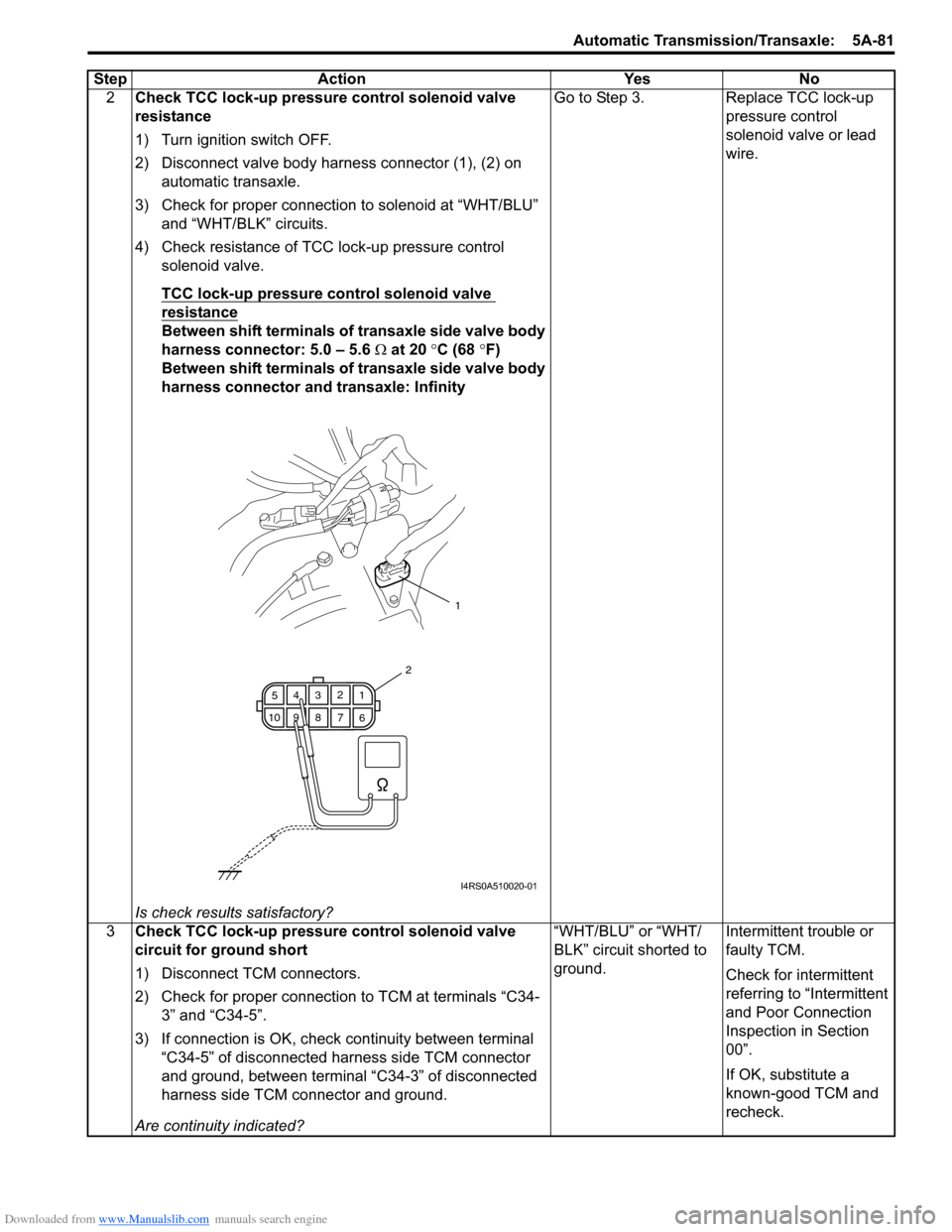
2Check TCC lock-up pressure control solenoid valve
resistance
1) Turn ignition switch OFF.
2) Disconnect valve body harness connector (1), (2) on
automatic transaxle.
3) Check for proper connection to solenoid at “WHT/BLU” and “WHT/BLK” circuits.
4) Check resistance of TCC lock-up pressure control
solenoid valve.
TCC lock-up pressure control solenoid valve
resistance
Between shift terminals of transaxle side valve body
harness connector: 5.0 – 5.6 Ω at 20 °C (68 °F)
Between shift terminals of transaxle side valve body
harness connector and transaxle: Infinity
Is check results satisfactory? Go to Step 3. Replace TCC lock-up
pressure control
solenoid valve or lead
wire.
3 Check TCC lock-up pressure control solenoid valve
circuit for ground short
1) Disconnect TCM connectors.
2) Check for proper connection to TCM at terminals “C34-
3” and “C34-5”.
3) If connection is OK, check continuity between terminal
“C34-5” of disconnected harness side TCM connector
and ground, between terminal “C34-3” of disconnected
harness side TCM connector and ground.
Are continuity indicated? “WHT/BLU” or “WHT/
BLK” circuit shorted to
ground.
Intermittent trouble or
faulty TCM.
Check for intermittent
referring to “Intermittent
and Poor Connection
Inspection in Section
00”.
If OK, substitute a
known-good TCM and
recheck.
Step Action Yes No
1
6
7
89
10 5
43 2
1
2
I4RS0A510020-01
Page 726 of 1496
Downloaded from www.Manualslib.com manuals search engine 5A-82 Automatic Transmission/Transaxle:
Inspection of TCM and Its CircuitsS7RS0B5104045
TCM and its circuits can be checked at TCM wiring connec tors by measuring voltage, pulse signal and resistance.
CAUTION!
TCM cannot be checked by itself, it is strictly prohibited to connect voltmeter or ohmmeter to TCM with
connector disconnected from it.
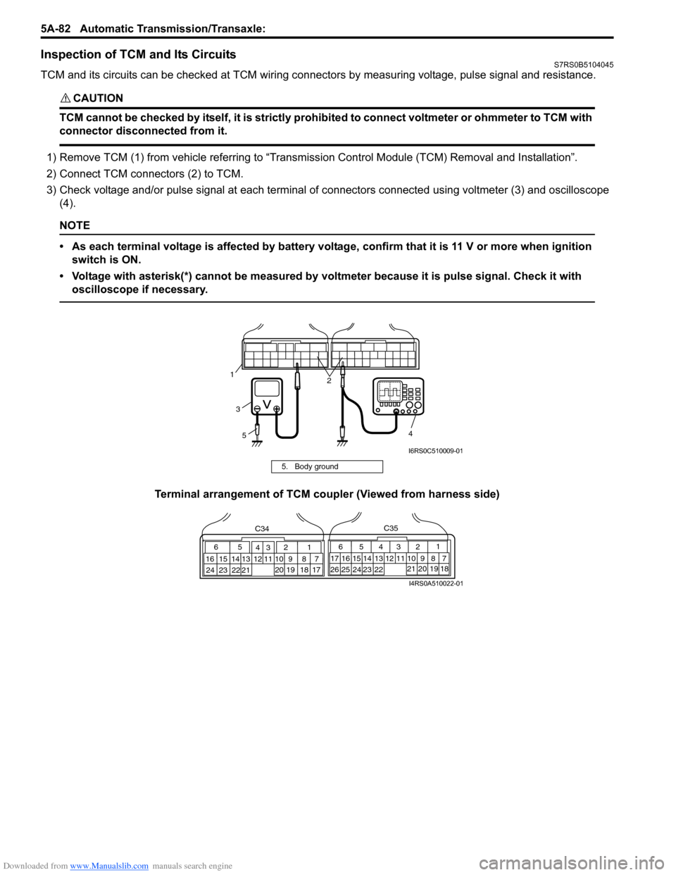
1) Remove TCM (1) from vehicle referring to “Transmission Control Module (TCM) Removal and Installation”.
2) Connect TCM connectors (2) to TCM.
3) Check voltage and/or pulse signal at each terminal of connectors connected using voltmeter (3) and oscilloscope
(4).
NOTE
• As each terminal voltage is affected by battery voltag e, confirm that it is 11 V or more when ignition
switch is ON.
• Voltage with asterisk(*) cannot be measured by voltmeter because it is pulse signal. Check it with oscilloscope if necessary.
Terminal arrangement of TCM coupler (Viewed from harness side)
5. Body ground
3
5 4
12
I6RS0C510009-01
65
16 15 14 13 12 11 43
24 23 2122 10 9 8 721
1920 18 17
C34
17 16
26 25
15 14
65 3
42
13 12
23 2224 11 10 9
21 20 19 87
18
1
C35
I4RS0A510022-01
Page 745 of 1496
Downloaded from www.Manualslib.com manuals search engine Automatic Transmission/Transaxle: 5A-101
Pressure Control Solenoid Valves (Pressure
Control Solenoid and TCC Pressure Control
Solenoid) Removal and Installation
S7RS0B5106024
Removal1) Disconnect negative cable at battery.
2) Lift up vehicle.
3) Remove drain plug and drain A/T fluid.
4) Install drain plug.
Tightening torque
A/T fluid drain plug: 17 N·m (1.7 kgf-m, 12.5 lb-ft)
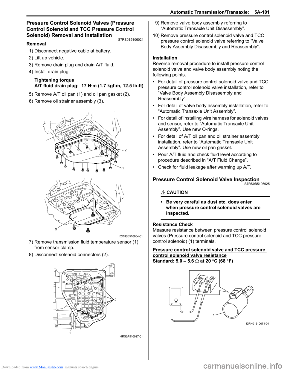
5) Remove A/T oil pan (1) and oil pan gasket (2).
6) Remove oil strain er assembly (3).
7) Remove transmission fluid temperature sensor (1) from sensor clamp.
8) Disconnect solenoid connectors (2). 9) Remove valve body assembly referring to
“Automatic Transaxl e Unit Disassembly”.
10) Remove pressure control solenoid valve and TCC pressure control solenoid valve referring to “Valve
Body Assembly Disassembly and Reassembly”.
Installation
Reverse removal procedure to install pressure control
solenoid valve and valve body assembly noting the
following points.
• For detail of pressure control solenoid valve and TCC pressure control solenoid va lve installation, refer to
“Valve Body Assembly Disassembly and
Reassembly”.
• For detail of valve body asse mbly installation, refer to
“Automatic Transaxle Unit Assembly”.
• For detail of installing wire harness for solenoid valves and sensor, refer to “Automatic Transaxle Unit
Assembly”. Use new O-rings.
• For detail of A/T oil pan and oil strainer assembly
installation, refer to “A utomatic Transaxle Unit
Assembly”. Use new oil pan gasket.
• Pour A/T fluid and check fluid level according to procedure described in “A/T Fluid Change”.
• Check for fluid leakage after warming up A/T.
Pressure Control Solenoid Valve InspectionS7RS0B5106025
CAUTION!
• Be very careful as dust etc. does enter when pressure control solenoid valves are
inspected.
Resistance Check
Measure resistance between pressure control solenoid
valves (Pressure control solenoid and TCC pressure
control solenoid) (1) terminals.
Pressure control solenoid valve and TCC pressure
control solenoid valve resistance
Standard: 5.0 – 5.6 Ω at 20 °C (68 °F)
I2RH0B510054-01
1 2I4RS0A510027-01
1
I2RH01510071-01
Page 783 of 1496
Downloaded from www.Manualslib.com manuals search engine Automatic Transmission/Transaxle: 5A-139
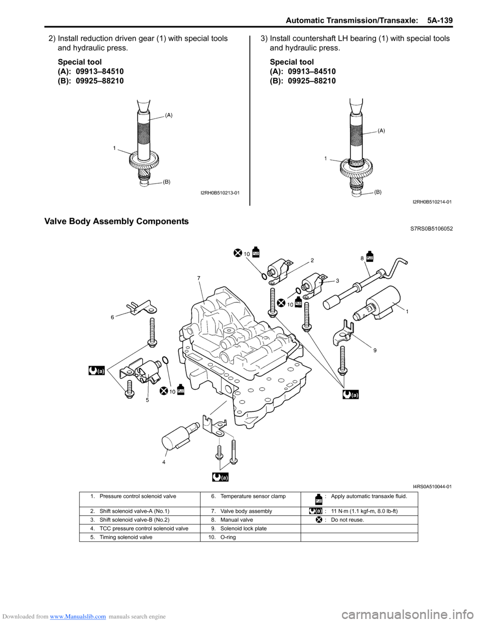
2) Install reduction driven gear (1) with special tools and hydraulic press.
Special tool
(A): 09913–84510
(B): 09925–88210 3) Install countershaft LH bearing (1) with special tools
and hydraulic press.
Special tool
(A): 09913–84510
(B): 09925–88210
Valve Body Assembly ComponentsS7RS0B5106052
I2RH0B510213-01
I2RH0B510214-01
I4RS0A510044-01
1. Pressure control solenoid valve 6. Temperature sensor clamp : Apply automatic transaxle fluid.
2. Shift solenoid valve-A (No.1) 7. Valve body assembly: 11 N⋅m (1.1 kgf-m, 8.0 lb-ft)
3. Shift solenoid valve-B (No.2) 8. Manual valve: Do not reuse.
4. TCC pressure control solenoid valve 9. Solenoid lock plate
5. Timing solenoid valve 10. O-ring
Page 784 of 1496
Downloaded from www.Manualslib.com manuals search engine 5A-140 Automatic Transmission/Transaxle:
Valve Body Assembly Disassembly and
Reassembly
S7RS0B5106053
CAUTION!
When replacing pressure control solenoid
valve and/or TCC pressure control solenoid
valve, it is strictly required to replace it
together with valve body assembly as a set.
Replacing pressure control solenoid valve
and/or TCC pressure control solenoid valve
independently may cause excessive shift
shock.
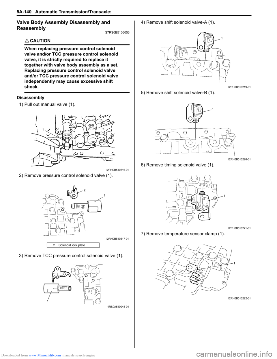
Disassembly1) Pull out manual valve (1).
2) Remove pressure cont rol solenoid valve (1).
3) Remove TCC pressure control solenoid valve (1). 4) Remove shift solenoid valve-A (1).
5) Remove shift solenoid valve-B (1).
6) Remove timing solenoid valve (1).
7) Remove temperature sensor clamp (1).
2. Solenoid lock plate
I2RH0B510216-01
I2RH0B510217-01
1
I4RS0A510045-01
I2RH0B510219-01
I2RH0B510220-01
I2RH0B510221-01
I2RH0B510222-01
Page 880 of 1496
Downloaded from www.Manualslib.com manuals search engine 6B-9 Steering Wheel and Column:
Ignition Switch Cylinder Assembly Removal
and Installation (Non- Keyless Start Model)
S7RS0B6206008
Removal1) Disconnect negative (–) cable at battery.
2) Disable air bag system referring to “Disabling Air Bag System in Section 8B”.
3) Remove steering column upper and lower covers.
4) Remove immobilizer co ntrol module referring to
“Immobilizer Control Modu le (ICM) Removal and
Installation in Section 10C”.
5) Remove ignition switch cy linder assembly as follows.
a) Turn ignition key to “ACC” position.
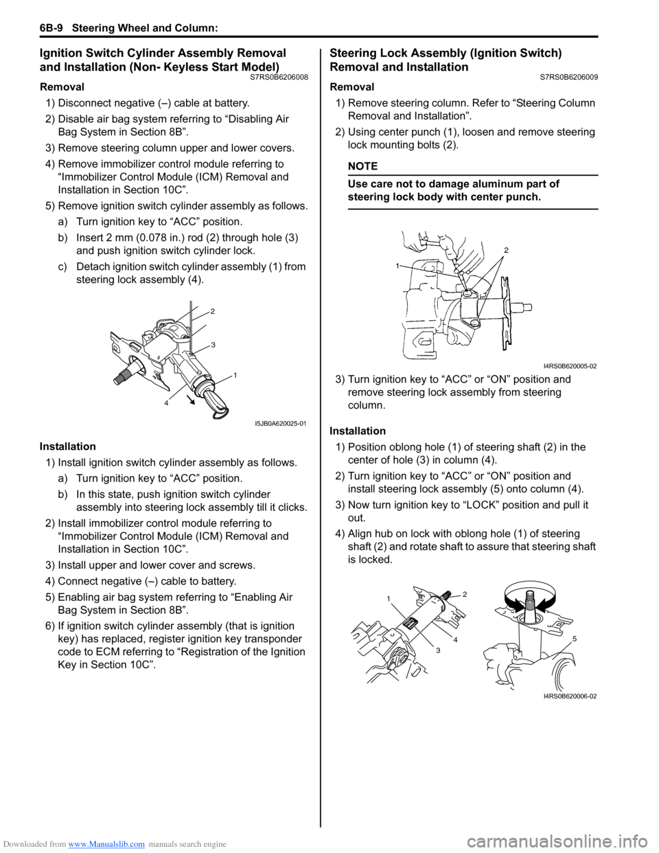
b) Insert 2 mm (0.078 in.) rod (2) through hole (3) and push ignition switch cylinder lock.
c) Detach ignition switch cylinder assembly (1) from steering lock assembly (4).
Installation 1) Install ignition switch cy linder assembly as follows.
a) Turn ignition key to “ACC” position.
b) In this state, push ignition switch cylinder assembly into steering lock assembly till it clicks.
2) Install immobilizer cont rol module referring to
“Immobilizer Control Modu le (ICM) Removal and
Installation in Section 10C”.
3) Install upper and lower cover and screws.
4) Connect negative (–) cable to battery.
5) Enabling air bag system referring to “Enabling Air Bag System in Section 8B”.
6) If ignition switch cylinder assembly (that is ignition
key) has replaced, register ignition key transponder
code to ECM referring to “R egistration of the Ignition
Key in Section 10C”.
Steering Lock Assembly (Ignition Switch)
Removal and Installation
S7RS0B6206009
Removal
1) Remove steering column. Refer to “Steering Column
Removal and Installation”.
2) Using center punch (1), loosen and remove steering lock mounting bolts (2).
NOTE
Use care not to damage aluminum part of
steering lock body with center punch.
3) Turn ignition key to “ACC” or “ON” position and remove steering lock a ssembly from steering
column.
Installation 1) Position oblong hole (1) of steering shaft (2) in the center of hole (3) in column (4).
2) Turn ignition key to “ACC” or “ON” position and install steering lock assemb ly (5) onto column (4).
3) Now turn ignition key to “LOCK” position and pull it out.
4) Align hub on lock with oblong hole (1) of steering shaft (2) and rotate shaft to assure that steering shaft
is locked.
2
3
1
4
I5JB0A620025-01
I4RS0B620005-02
1
32
4
5
I4RS0B620006-02
Page 894 of 1496
Downloaded from www.Manualslib.com manuals search engine 6C-12 Power Assisted Steering System:
Scan Tool Data Definitions
Battery Voltage
This parameter indicates battery positive voltage.
TQS Power Supply (Torque Sensor Power Supply, V)
This parameter indicates the power supply voltage which
the P/S control module supplies to the torque sensor.
TQS Main Torque (Torque Sensor Main Torque, N ⋅m)
The torque sensor is installed to detect the steering force
and the steering directio n. It consists of two
potentiometers and the main torque sensor is one of
these.
TQS Sub Torque (Torque Sensor Sub Torque, N ⋅m)
The torque sensor is installed to detect the steering force
and the steering directio n. It consists of two
potentiometers and the sub-torque sensor is one of
these. Its output characteristics are compared with those
of the main torque sensor.
Assist Torque (N ⋅m)
This parameter is an internal parameter of the P/S
control module. It is obtained by computing the torque
sensor input signal. Motor Control (Motor Control Current, A)
Based on the input signal, the P/S control module
determines the assist amount
and controls the current to
the motor suitable for that a ssist amount. This parameter
indicates that control value.
Motor Monitor (Motor Monitor Current, A)
This parameter indicates the actually measured value of
the current flowing to the motor. The motor circuit
condition is diagnosed by co mparing this parameter with
“Motor Control” parameter described previously.
Vehicle Speed (km/h, MPH)
Vehicle speed signal is fed from BCM. P/S control
module determines the amount of power assist based on
this vehicle speed signal and the torque sensor signal.
Engine Speed (rpm)
Engine speed signal is fed from the ECM so that it can
be used for trouble diagnos is of the electric power
steering system.
Motor Volt (V)
This parameter indicates the voltage between motor
terminals.
Ignition switch (ON, OFF)
This parameter indicates the condition of the power
supply through the ignition switch.
Visual InspectionS7RS0B6304007
Visually check the following pats and system.
P/S System Symptom DiagnosisS7RS0B6304008
This section describes trouble diagnosis of the P/S system parts whose trouble is not indicated by the on-board
diagnostic system (self-diagnostic functi on). When no malfunction is indicated by the on-board diagnostic system
(self-diagnosis function) and those stee ring basic parts as described in “Steering Symptom Diagnosis in Section 6A”
are all in good condition, check the following power steer ing system parts which may be a possible cause for each
symptom of the steering. Inspection Item Referring section
Battery Level, leakage, color “Batte ry Description in Section 1J”
Connectors of electric wire
harness Disconnection friction “Intermittent and Poor
Connection Inspection in Section 00”
Fuses Burning “Cautions in Body Electric al System Servicing in Section 9A”
Parts Installation, damage
Other parts that can be checked visually
Condition Possible cause Correction / Reference Item
Steering wheel feels
heavy (Perform “Steering
Force Check” before
diagnosis.) Steering wheel installed improperly
(twisted)
Install steering wheel correctly.
Poor performance of torque sensor Check torque sensor referring to “Torque
Sensor and Its Circuit Inspection”.
Poor performance of P/S motor Check motor referring to “P/S Motor and Its
Circuit Inspection”.
Steering gear case assembly faulty Replace.
Poor performance of vehicle speed
signal from ECM Check vehicle speed signal circuit referring to
“DTC C1121 / C1123 / C1124: VSS Circuit
Failure”.