ig 2 sig SUZUKI SWIFT 2006 2.G Service Workshop Manual
[x] Cancel search | Manufacturer: SUZUKI, Model Year: 2006, Model line: SWIFT, Model: SUZUKI SWIFT 2006 2.GPages: 1496, PDF Size: 34.44 MB
Page 280 of 1496
Downloaded from www.Manualslib.com manuals search engine 1C-8 Engine Electrical Devices:
Installation
Reverse removal procedure noting the following.
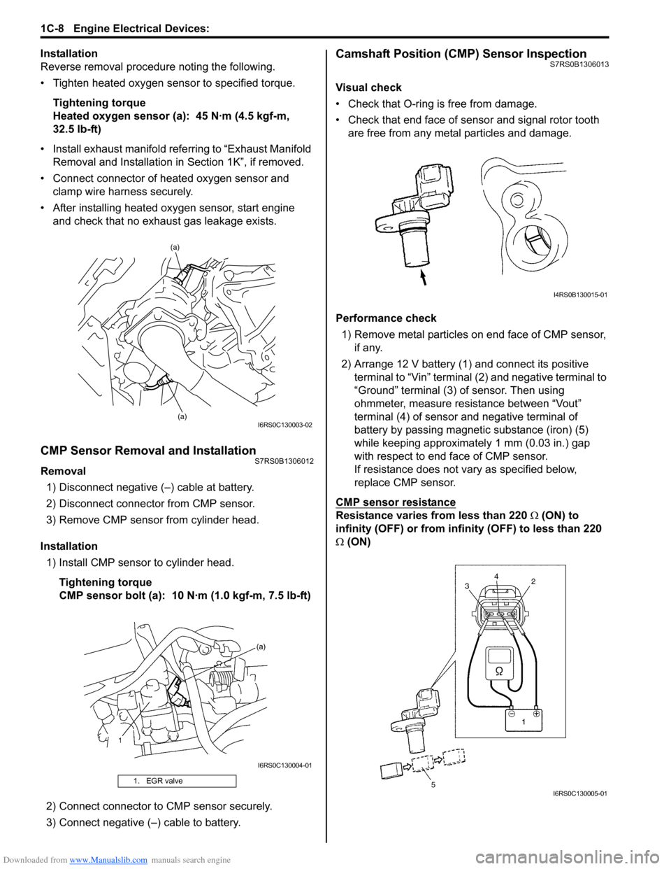
• Tighten heated oxygen sensor to specified torque.Tightening torque
Heated oxygen sensor (a): 45 N·m (4.5 kgf-m,
32.5 lb-ft)
• Install exhaust manifold referring to “Exhaust Manifold Removal and Installation in Section 1K”, if removed.
• Connect connector of heated oxygen sensor and clamp wire harness securely.
• After installing heated oxygen sensor, start engine and check that no exhaust gas leakage exists.
CMP Sensor Removal and InstallationS7RS0B1306012
Removal
1) Disconnect negative (–) cable at battery.
2) Disconnect connector from CMP sensor.
3) Remove CMP sensor from cylinder head.
Installation 1) Install CMP sensor to cylinder head.
Tightening torque
CMP sensor bolt (a): 10 N·m (1.0 kgf-m, 7.5 lb-ft)
2) Connect connector to CMP sensor securely.
3) Connect negative (–) cable to battery.
Camshaft Position (CMP) Sensor InspectionS7RS0B1306013
Visual check
• Check that O-ring is free from damage.
• Check that end face of sensor and signal rotor tooth are free from any metal particles and damage.
Performance check 1) Remove metal particles on end face of CMP sensor, if any.
2) Arrange 12 V battery (1) and connect its positive terminal to “Vin” terminal (2) and negative terminal to
“Ground” terminal (3) of sensor. Then using
ohmmeter, measure resistance between “Vout”
terminal (4) of sensor and negative terminal of
battery by passing magnetic substance (iron) (5)
while keeping approximately 1 mm (0.03 in.) gap
with respect to end face of CMP sensor.
If resistance does not vary as specified below,
replace CMP sensor.
CMP sensor resistance
Resistance varies from less than 220 Ω (ON) to
infinity (OFF) or from infinity (OFF) to less than 220
Ω (ON)
1. EGR valve
(a)
(a)
I6RS0C130003-02
I6RS0C130004-01
I4RS0B130015-01
I6RS0C130005-01
Page 281 of 1496
Downloaded from www.Manualslib.com manuals search engine Engine Electrical Devices: 1C-9
CKP Sensor Removal and InstallationS7RS0B1306014
Removal1) Disconnect negative (–) cable at battery.
2) Remove generator drive belt refer to “Water Pump / Generator Drive Belt Remo val and Installation in
Section 1J”.
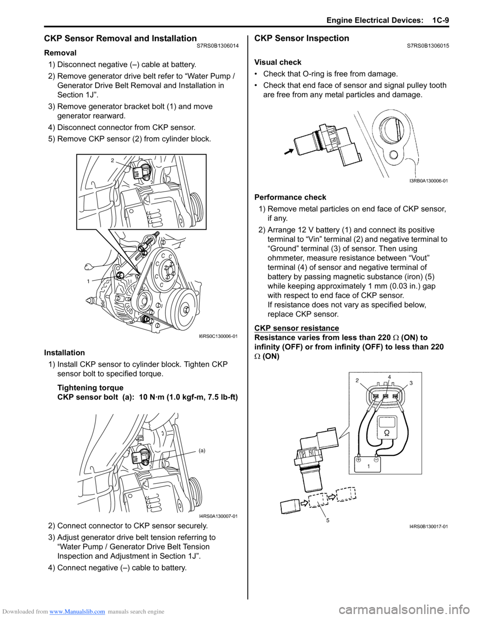
3) Remove generator bracket bolt (1) and move generator rearward.
4) Disconnect connector from CKP sensor.
5) Remove CKP sensor (2) from cylinder block.
Installation 1) Install CKP sensor to cylinder block. Tighten CKP sensor bolt to specified torque.
Tightening torque
CKP sensor bolt (a): 10 N·m (1.0 kgf-m, 7.5 lb-ft)
2) Connect connector to CKP sensor securely.
3) Adjust generator drive belt tension referring to “Water Pump / Generator Drive Belt Tension
Inspection and Adjustment in Section 1J”.
4) Connect negative (–) cable to battery.
CKP Sensor InspectionS7RS0B1306015
Visual check
• Check that O-ring is free from damage.
• Check that end face of sensor and signal pulley tooth are free from any metal particles and damage.
Performance check 1) Remove metal particles on end face of CKP sensor, if any.
2) Arrange 12 V battery (1) and connect its positive terminal to “Vin” terminal (2) and negative terminal to
“Ground” terminal (3) of sensor. Then using
ohmmeter, measure resistance between “Vout”
terminal (4) of sensor and negative terminal of
battery by passing magnetic substance (iron) (5)
while keeping approximately 1 mm (0.03 in.) gap
with respect to end face of CKP sensor.
If resistance does not vary as specified below,
replace CKP sensor.
CKP sensor resistance
Resistance varies from less than 220 Ω (ON) to
infinity (OFF) or from infinity (OFF) to less than 220
Ω (ON)
2
1
I6RS0C130006-01
(a)
I4RS0A130007-01
I3RB0A130006-01
I4RS0B130017-01
Page 283 of 1496
Downloaded from www.Manualslib.com manuals search engine Engine Electrical Devices: 1C-11
MAF and IAT Sensor On-Vehicle InspectionS7RS0B1306018
NOTE
Before performed this inspection, be sure to
read the “Precautions of ECM Circuit
Inspection in Section 1A”.
1) Disconnect negative (–) cable at battery.
2) Disconnect MAF and IAT sensor connector.
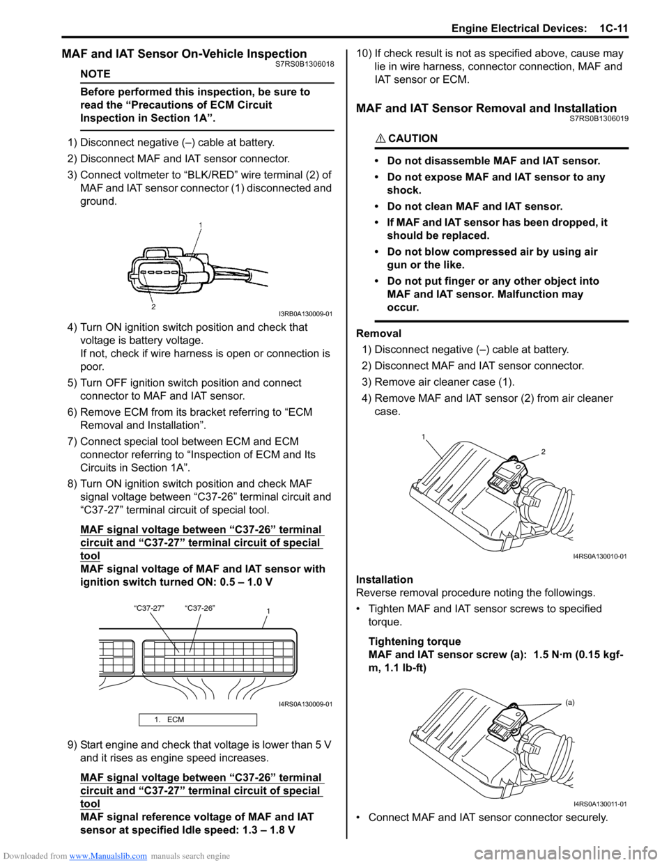
3) Connect voltmeter to “BLK/RED” wire terminal (2) of
MAF and IAT sensor connector (1) disconnected and
ground.
4) Turn ON ignition switch position and check that voltage is battery voltage.
If not, check if wire harness is open or connection is
poor.
5) Turn OFF ignition switch position and connect connector to MAF and IAT sensor.
6) Remove ECM from its bracket referring to “ECM Removal and Installation”.
7) Connect special tool between ECM and ECM connector referring to “Inspection of ECM and Its
Circuits in Section 1A”.
8) Turn ON ignition switch position and check MAF signal voltage between “C37-26” terminal circuit and
“C37-27” terminal circuit of special tool.
MAF signal voltage between “C37-26” terminal
circuit and “C37-27” termi nal circuit of special
tool
MAF signal voltage of MAF and IAT sensor with
ignition switch turned ON: 0.5 – 1.0 V
9) Start engine and check that voltage is lower than 5 V and it rises as engine speed increases.
MAF signal voltage between “C37-26” terminal
circuit and “C37-27” termi nal circuit of special
tool
MAF signal reference voltage of MAF and IAT
sensor at specified Idle speed: 1.3 – 1.8 V 10) If check result is not as
specified above, cause may
lie in wire harness, connec tor connection, MAF and
IAT sensor or ECM.
MAF and IAT Sensor Removal and InstallationS7RS0B1306019
CAUTION!
• Do not disassemble MAF and IAT sensor.
• Do not expose MAF and IAT sensor to any shock.
• Do not clean MAF and IAT sensor.
• If MAF and IAT sensor has been dropped, it should be replaced.
• Do not blow compressed air by using air gun or the like.
• Do not put finger or any other object into MAF and IAT sensor. Malfunction may
occur.
Removal
1) Disconnect negative (–) cable at battery.
2) Disconnect MAF and IAT sensor connector.
3) Remove air cleaner case (1).
4) Remove MAF and IAT sensor (2) from air cleaner case.
Installation
Reverse removal procedure noting the followings.
• Tighten MAF and IAT sensor screws to specified torque.
Tightening torque
MAF and IAT sensor screw (a): 1.5 N·m (0.15 kgf-
m, 1.1 lb-ft)
• Connect MAF and IAT sensor connector securely.
1. ECM
I3RB0A130009-01
“C37-27” “C37-26” 1
I4RS0A130009-01
1
2
I4RS0A130010-01
(a)
I4RS0A130011-01
Page 287 of 1496
Downloaded from www.Manualslib.com manuals search engine Engine Mechanical: 1D-2
Camshaft Position Control (VVT Variable Valve Timing) System DescriptionS7RS0B1401002
System Description
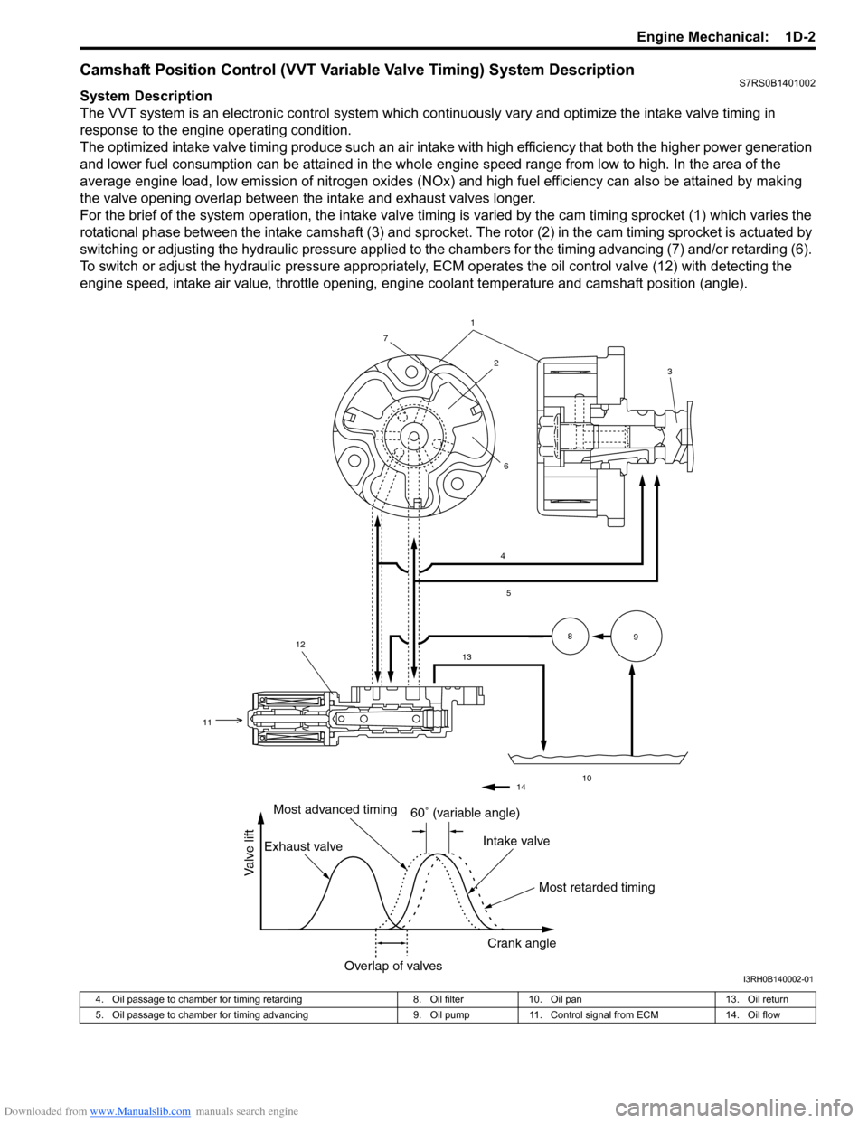
The VVT system is an electronic control system which continuously vary and optimize the intake valve timing in
response to the engine operating condition.
The optimized intake valve timing produce such an air intake with high efficiency that both the higher power generation
and lower fuel consumption can be attained in the whole engine speed range from low to high. In the area of the
average engine load, low emission of nitrogen oxides (NOx) and high fuel efficiency can also be attained by making
the valve opening overlap between the intake and exhaust valves longer.
For the brief of the system operation, the intake valve timing is varied by the cam timing sprocket (1) which varies the
rotational phase between the intake camshaft (3) and sprocket . The rotor (2) in the cam timing sprocket is actuated by
switching or adjusting the hydraulic pressure applied to the chambers for the timing advancing (7) and/or retarding (6).
To switch or adjust the hydraulic pressure appropriately, ECM operates the oil control valve (12) with detecting the
engine speed, intake air value, throttle opening, engine coolant temperature and camshaft position (angle).
1
4
5
13
10
89
2
7
6
12
11
3
14
60� (variable angle)
Most retarded timing
Most advanced timing
Exhaust valve Intake valve
Crank angle
Overlap of valves
Valve lift
I3RH0B140002-01
4. Oil passage to chamber for timing retarding 8. Oil filter10. Oil pan 13. Oil return
5. Oil passage to chamber for timing advancing 9. Oil pump11. Control signal from ECM 14. Oil flow
Page 288 of 1496
Downloaded from www.Manualslib.com manuals search engine 1D-3 Engine Mechanical:
Oil Control Valve
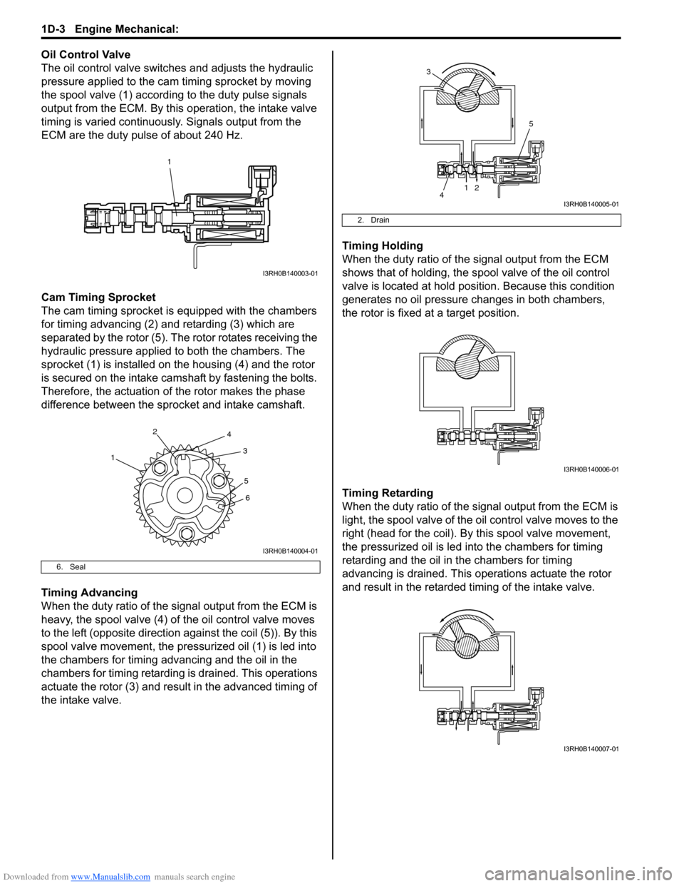
The oil control valve switches and adjusts the hydraulic
pressure applied to the cam timing sprocket by moving
the spool valve (1) according to the duty pulse signals
output from the ECM. By this operation, the intake valve
timing is varied continuously. Signals output from the
ECM are the duty pulse of about 240 Hz.
Cam Timing Sprocket
The cam timing sprocket is equipped with the chambers
for timing advancing (2) and retarding (3) which are
separated by the rotor (5). The rotor rotates receiving the
hydraulic pressure applied to both the chambers. The
sprocket (1) is installed on the housing (4) and the rotor
is secured on the intake camshaft by fastening the bolts.
Therefore, the actuation of the rotor makes the phase
difference between the sprocket and intake camshaft.
Timing Advancing
When the duty ratio of the signal output from the ECM is
heavy, the spool valve (4) of the oil control valve moves
to the left (opposite direction against the coil (5)). By this
spool valve movement, the pressurized oil (1) is led into
the chambers for timing advancing and the oil in the
chambers for timing retarding is drained. This operations
actuate the rotor (3) and result in the advanced timing of
the intake valve. Timing Holding
When the duty ratio of the si
gnal output from the ECM
shows that of holding, the sp ool valve of the oil control
valve is located at hold posi tion. Because this condition
generates no oil pressure changes in both chambers,
the rotor is fixed at a target position.
Timing Retarding
When the duty ratio of the sig nal output from the ECM is
light, the spool valve of the o il control valve moves to the
right (head for the coil). By this spool valve movement,
the pressurized oil is led into the chambers for timing
retarding and the oil in the chambers for timing
advancing is drained. This operations actuate the rotor
and result in the retarded timing of the intake valve.
6. Seal
1
I3RH0B140003-01
1 2
3
4
56
I3RH0B140004-01
2. Drain
12
5
4
3
I3RH0B140005-01
I3RH0B140006-01
I3RH0B140007-01
Page 335 of 1496
Downloaded from www.Manualslib.com manuals search engine Engine Mechanical: 1D-50
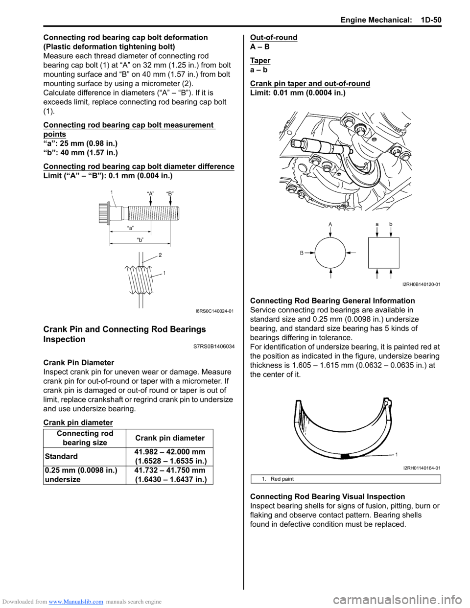
Connecting rod bearing cap bolt deformation
(Plastic deformation tightening bolt)
Measure each thread diameter of connecting rod
bearing cap bolt (1) at “A” on 32 mm (1.25 in.) from bolt
mounting surface and “B” on 40 mm (1.57 in.) from bolt
mounting surface by using a micrometer (2).
Calculate difference in diameters (“A” – “B”). If it is
exceeds limit, replace connecting rod bearing cap bolt
(1).
Connecting rod bearing cap bolt measurement
points
“a”: 25 mm (0.98 in.)
“b”: 40 mm (1.57 in.)
Connecting rod bearing cap bolt diameter difference
Limit (“A” – “B”): 0.1 mm (0.004 in.)
Crank Pin and Connecting Rod Bearings
Inspection
S7RS0B1406034
Crank Pin Diameter
Inspect crank pin for uneven wear or damage. Measure
crank pin for out-of-round or taper with a micrometer. If
crank pin is damaged or out-of round or taper is out of
limit, replace crankshaft or regrind crank pin to undersize
and use undersize bearing.
Crank pin diameter
Out-of-round
A – B
Ta p e r
a – b
Crank pin taper and out-of-round
Limit: 0.01 mm (0.0004 in.)
Connecting Rod Bearing General Information
Service connecting rod be arings are available in
standard size and 0.25 mm (0.0098 in.) undersize
bearing, and standard size bearing has 5 kinds of
bearings differing in tolerance.
For identification of undersize bearing, it is painted red at
the position as indicated in the figure, undersize bearing
thickness is 1.605 – 1.615 mm (0.0632 – 0.0635 in.) at
the center of it.
Connecting Rod Bearing Visual Inspection
Inspect bearing shells for signs of fusion, pitting, burn or
flaking and observe contact pattern. Bearing shells
found in defective condition must be replaced.
Connecting rod
bearing size Crank pin diameter
Standard 41.982 – 42.000 mm
(1.6528 – 1.6535 in.)
0.25 mm (0.0098 in.)
undersize 41.732 – 41.750 mm
(1.6430 – 1.6437 in.)
I6RS0C140024-01
1. Red paint
I2RH0B140120-01
I2RH01140164-01
Page 376 of 1496
Downloaded from www.Manualslib.com manuals search engine 1G-1 Fuel System:
Engine
Fuel System
Precautions
Precautions on Fuel System ServiceS7RS0B1700001
WARNING!
Before attempting service of any type on fuel system, the following should be always observed in
order to reduce the risk of fire and personal injury.
• Disconnect negative cable at battery.
• Do not smoke, and place no smoking signs near work area.
• Be sure to have CO
2 fire extinguisher handy.
• Be sure to perform work in a well-ventilated area and away from any open flames (such as gas hot heater).
• Wear safety glasses.
• To relieve fuel vapor pressure in fuel tank, remove fuel filler cap from fuel filler neck and then
reinstall it.
• As fuel feed line is still under high fuel pr essure even after stopping engine, loosening or
disconnecting fuel feed line directly may cause dangerous spout of fuel. Before loosening or
disconnecting fuel feed line, make sure to relieve fuel pressure referring to “Fuel Pressure Relief
Procedure”.
• A small amount of fuel may be released when the fuel line is disconnected. In order to reduce the risk of personal injury, cover a shop cloth to the fitting to be disconnected. Be sure to put that cloth
in an approved container after disconnecting.
• Never run engine with fuel pump relay disconnected when engine and exhaust system are hot.
• Note that fuel hose connection varies with each type of pipe. Be sure to connect and clamp each hose correctly referring to “Fuel Hose Disconnecting and Reconnecting”.
After connecting, make sure that it has no twist or kink.
• When installing inje ctor or fuel feed pipe, lubr icate its O-ring with gasoline.
General Description
Fuel System DescriptionS7RS0B1701001
CAUTION!
This engine requires the unleaded fuel only.
The leaded and/or low lead fuel can result in
engine damage and reduce the effectiveness
of the emission control system.
The main components of the fuel system are fuel tank,
fuel pump assembly (with fuel filter, fuel level gauge, fuel
pressure regulator, fuel feed line and fuel vapor line.
For the details of fuel flow, refer to “Fuel Delivery System
Diagram”.
Fuel Delivery System DescriptionS7RS0B1701002
The fuel delivery system consists of the fuel tank, fuel
pump assembly (with built-in f uel filter and fuel pressure
regulator), delivery pipe, injectors and fuel feed line.
The fuel in the fuel tank is pumped up by the fuel pump,
sent into delivery pipe and injected by the injectors.
As the fuel pump assembly is equipped with built-in fuel
filter and fuel pressure regulator, the fuel is filtered and
its pressure is regulated before being sent to the feed
pipe.
The excess fuel at fuel pressure regulation process is
returned back into the fuel tank.
Also, fuel vapor generated in fuel tank is led through the
fuel vapor line into the EVAP canister.
For system diagram, refer to “Fuel Delivery System
Diagram”.
Page 393 of 1496
Downloaded from www.Manualslib.com manuals search engine Ignition System: 1H-1
Engine
Ignition System
General Description
Ignition System ConstructionS7RS0B1801001
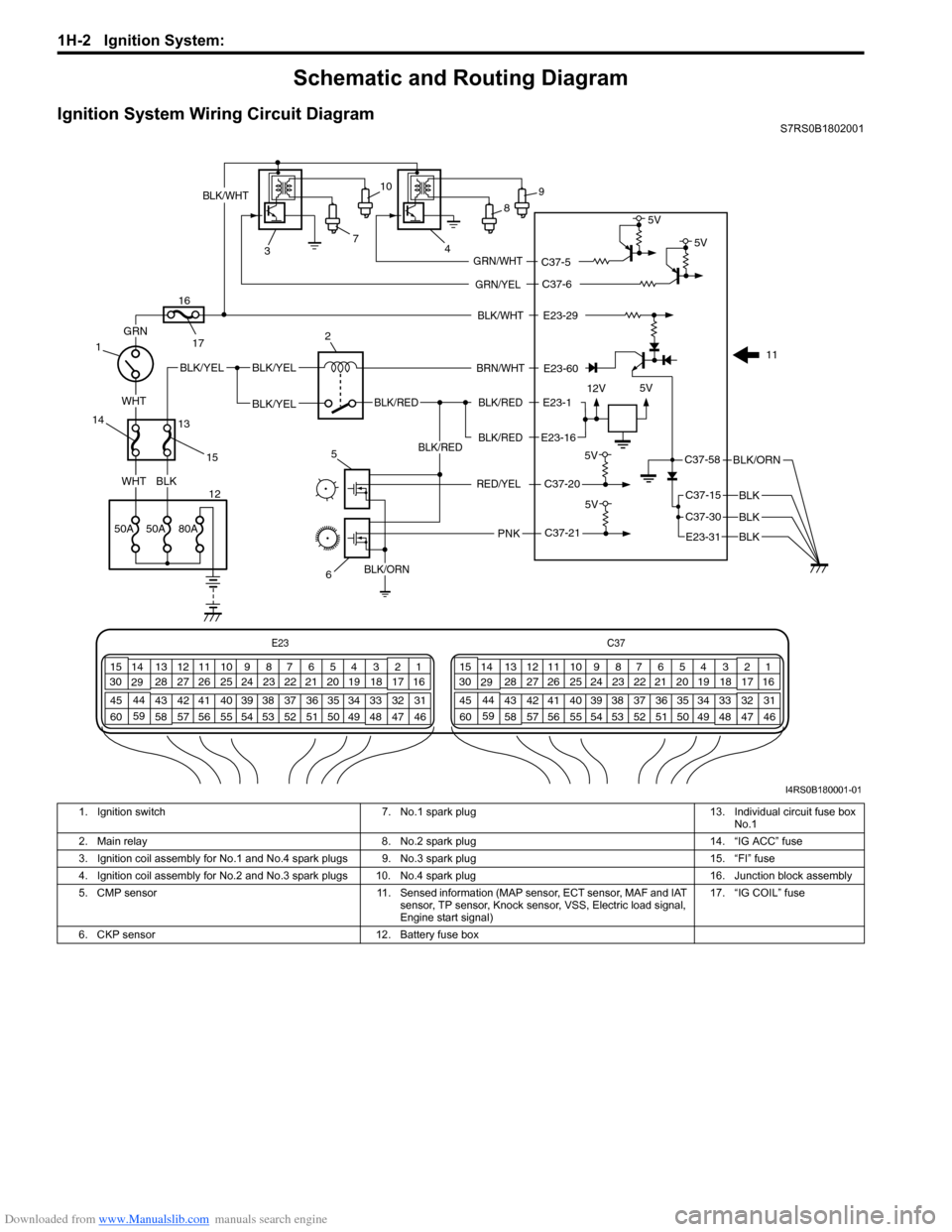
The ignition system is an electronic (distributorless) ignition system. It consists of the parts as described below.
• ECM
It detects the engine and vehicle conditions through the si gnals from the sensors, determines the most suitable
ignition timing and time for electricity to flow to the primar y coil and sends a signal to the ignitor (power unit) in the
ignition coil assembly.
• Ignition coil assembly (including an ignitor)
The ignition coil assembly has a built -in ignitor which turns ON and OFF the current flow to the primary coil
according to the signal from ECM. When the current flow to the primary coil is turned OFF, a high voltage is induced
in the secondary coil.
• High-tension cords and spark plugs
• CMP sensor (Camshaft position sensor) and CKP sensor (Crankshaft position sensor)
Using signals from these sensors, ECM identifies the specific cylinder whose piston is in the compression stroke,
detects the crank angle and adjusts in itial ignition timing automatically.
• TP sensor, ECT sensor, MAP sensor, MAF sensor, IAT sensor, knock sensor and other sensors / switches
Although this ignition system does not have a distributor, it has two ignition coil assemblies (one is for No.1 and No.4
spark plugs and the other is for No.2 and No.3 spark plugs). W hen an ignition signal is sent from ECM to the ignitor in
the ignition coil assembly for No.1 and No.4 spark plugs, a high voltage is induced in the secondary coil and that
passes through the high-tension cords and causes No.1 and No.4 spark plugs to spark simultaneously. Likewise,
when an ignition signal is sent to the ignitor in the ot her ignition coil assembly, No.2 and No.3 spark plugs spark
simultaneously.
Page 394 of 1496
Downloaded from www.Manualslib.com manuals search engine 1H-2 Ignition System:
Schematic and Routing Diagram
Ignition System Wiring Circuit DiagramS7RS0B1802001
E23-60
E23-29 12V 5V
5V
E23-1
E23-16
BLK/WHT
BLK/RED
BLK/RED BLK/RED
BLK/YELBLK/YEL
BLK/YEL
GRN
BLKWHT
WHT
BRN/WHT
BLK/ORN
BLK
BLK
C37-20
BLK/RED
PNK
5V
C37-21
BLK/WHT
7
3 4
1
12 5
6
2
11
8
9
10
GRN/YEL
GRN/WHT
C37-6
C37-5 5V
5V
RED/YEL
C37-58
C37-15
C37-30
E23
C37
34
1819
567
1011
17
20
47 46
495051
2122
52 16
25 9
24
14
29
55
57 54 53
59
60 58 2
262728
15
30
56 4832 31
34353637
40
42 39 38
44
45 43 41 331
1213
238
34
1819
567
1011
17
20
47 46
495051
2122
52 16
25 9
24
14
29
55
57 54 53
59
60 58 2
262728
15
30
56 4832 31
34353637
40
42 39 38
44
45 43 41 331
1213
238
13
14
15
16
17
50A50A80A
BLK/ORN
E23-31 BLK
I4RS0B180001-01
1. Ignition switch 7. No.1 spark plug 13. Individual circuit fuse box
No.1
2. Main relay 8. No.2 spark plug 14. “IG ACC” fuse
3. Ignition coil assembly for No.1 and No.4 spark plugs 9. No.3 spark plug 15. “FI” fuse
4. Ignition coil assembly for No.2 and No.3 spark plugs 10. No.4 spark plug 16. Junction block assembly
5. CMP sensor 11. Sensed information (MAP sensor, ECT sensor, MAF and IAT
sensor, TP sensor, Knock sensor, VSS, Electric load signal,
Engine start signal) 17. “IG COIL” fuse
6. CKP sensor 12. Battery fuse box
Page 396 of 1496
Downloaded from www.Manualslib.com manuals search engine 1H-4 Ignition System:
Diagnostic Information and Procedures
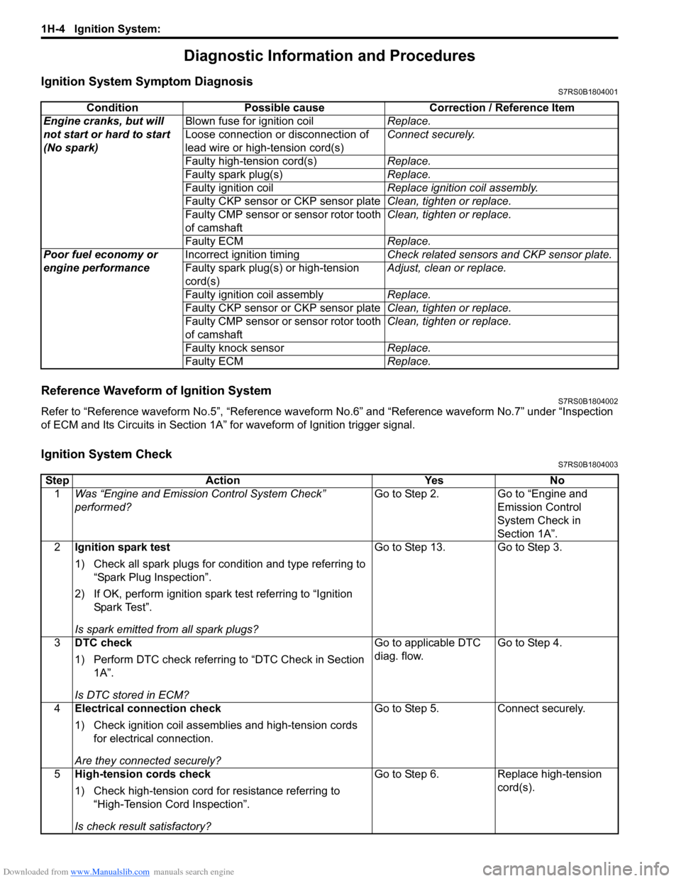
Ignition System Symptom DiagnosisS7RS0B1804001
Reference Waveform of Ignition SystemS7RS0B1804002
Refer to “Reference waveform No.5”, “Reference waveform No.6” and “Reference waveform No.7” under “Inspection
of ECM and Its Circuits in Section 1A” for waveform of Ignition trigger signal.
Ignition System CheckS7RS0B1804003
Condition Possible cause Correction / Reference Item
Engine cranks, but will
not start or hard to start
(No spark) Blown fuse for ignition coil
Replace.
Loose connection or disconnection of
lead wire or high-tension cord(s) Connect securely.
Faulty high-tension cord(s) Replace.
Faulty spark plug(s) Replace.
Faulty ignition coil Replace ignition coil assembly.
Faulty CKP sensor or CKP sensor plate Clean, tighten or replace.
Faulty CMP sensor or sensor rotor tooth
of camshaft Clean, tighten or replace.
Faulty ECM Replace.
Poor fuel economy or
engine performance Incorrect ignition timing
Check related sensors and CKP sensor plate.
Faulty spark plug(s) or high-tension
cord(s) Adjust, clean or replace.
Faulty ignition coil assembly Replace.
Faulty CKP sensor or CKP sensor plate Clean, tighten or replace.
Faulty CMP sensor or sensor rotor tooth
of camshaft Clean, tighten or replace.
Faulty knock sensor Replace.
Faulty ECM Replace.
StepAction YesNo
1 Was “Engine and Emission Control System Check”
performed? Go to Step 2.
Go to “Engine and
Emission Control
System Check in
Section 1A”.
2 Ignition spark test
1) Check all spark plugs for condition and type referring to
“Spark Plug Inspection”.
2) If OK, perform ignition spark test referring to “Ignition Spar k Tes t”.
Is spark emitted from all spark plugs? Go to Step 13. Go to Step 3.
3 DTC check
1) Perform DTC check referring to “DTC Check in Section
1A”.
Is DTC stored in ECM? Go to applicable DTC
diag. flow.
Go to Step 4.
4 Electrical connection check
1) Check ignition coil assemblies and high-tension cords
for electrical connection.
Are they connected securely? Go to Step 5.
Connect securely.
5 High-tension cords check
1) Check high-tension cord for resistance referring to
“High-Tension Cord Inspection”.
Is check result satisfactory? Go to Step 6.
Replace high-tension
cord(s).