start system SUZUKI SWIFT 2006 2.G Service Workshop Manual
[x] Cancel search | Manufacturer: SUZUKI, Model Year: 2006, Model line: SWIFT, Model: SUZUKI SWIFT 2006 2.GPages: 1496, PDF Size: 34.44 MB
Page 694 of 1496
Downloaded from www.Manualslib.com manuals search engine 5A-50 Automatic Transmission/Transaxle:
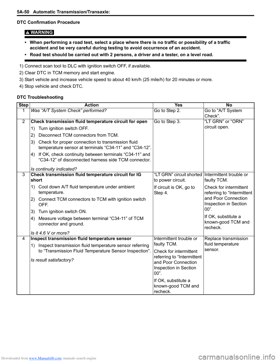
DTC Confirmation Procedure
WARNING!
• When performing a road test, select a place where there is no traffic or possibility of a traffic
accident and be very careful during testing to avoid occurrence of an accident.
• Road test should be carried out with 2 persons, a driver and a tester, on a level road.
1) Connect scan tool to DLC with ig nition switch OFF, if available.
2) Clear DTC in TCM memory and start engine.
3) Start vehicle and increase vehicle speed to about 40 km/h (25 mile/h) for 20 minutes or more.
4) Stop vehicle and check DTC.
DTC Troubleshooting Step Action Yes No 1 Was “A/T System Check” performed? Go to Step 2. Go to “A/T System
Check”.
2 Check transmission fluid temperature circuit for open
1) Turn ignition switch OFF.
2) Disconnect TCM connectors from TCM.
3) Check for proper connection to transmission fluid
temperature sensor at terminals “C34-11” and “C34-12”.
4) If OK, check continuity between terminals “C34-11” and “C34-12” of disconnected harness side TCM connector.
Is continuity indicated? Go to Step 3. “LT GRN” or “ORN”
circuit open.
3 Check transmission fluid temperature circuit for IG
short
1) Cool down A/T fluid te mperature under ambient
temperature.
2) Connect TCM connectors to TCM with ignition switch OFF.
3) Turn ignition switch ON.
4) Measure voltage between terminal “C34-11” of TCM connector and ground.
Is it 4.6 V or more? “LT GRN” circuit shorted
to power circuit.
If circuit is OK, go to
St ep 4 .
Intermittent trouble or
faulty TCM.
Check for intermittent
referring to “Intermittent
and Poor Connection
Inspection in Section
00”.
If OK, substitute a
known-good TCM and
recheck.
4 Inspect transmission fluid temperature sensor
1) Inspect transmission fluid temperature sensor referring
to “Transmission Fluid Temperature Sensor Inspection”.
Is result satisfactory? Intermittent trouble or
faulty TCM.
Check for intermittent
referring to “Intermittent
and Poor Connection
Inspection in Section
00”.
If OK, substitute a
known-good TCM and
recheck.Replace transmission
fluid temperature
sensor.
Page 695 of 1496
Downloaded from www.Manualslib.com manuals search engine Automatic Transmission/Transaxle: 5A-51
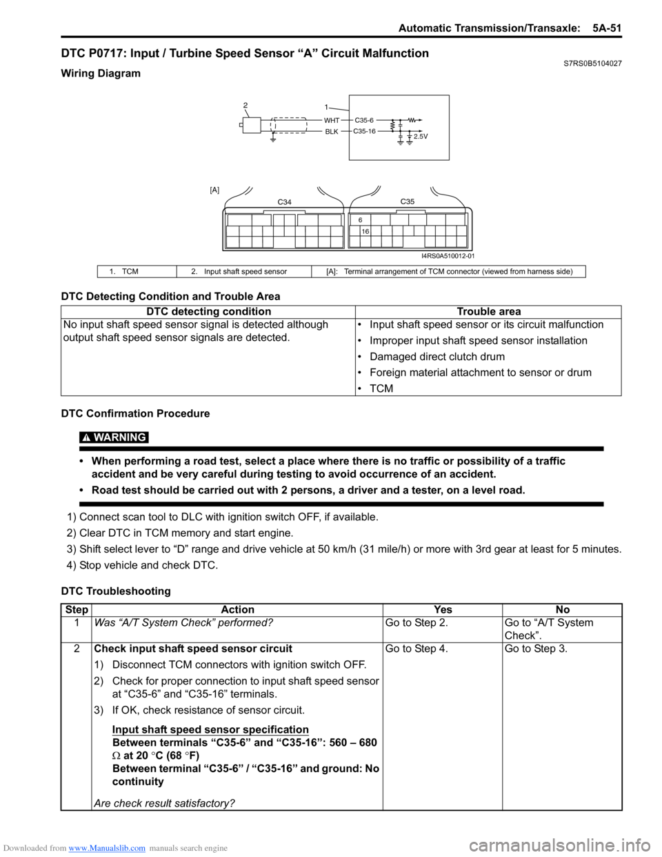
DTC P0717: Input / Turbine Speed Sensor “A” Circuit MalfunctionS7RS0B5104027
Wiring Diagram
DTC Detecting Condition and Trouble Area
DTC Confirmation Procedure
WARNING!
• When performing a road test, select a place where there is no traffic or possibility of a traffic accident and be very careful during testing to avoid occurrence of an accident.
• Road test should be carried out with 2 persons, a driver and a tester, on a level road.
1) Connect scan tool to DLC with ig nition switch OFF, if available.
2) Clear DTC in TCM memory and start engine.
3) Shift select lever to “D” range and drive vehicle at 50 km /h (31 mile/h) or more with 3rd gear at least for 5 minutes.
4) Stop vehicle and check DTC.
DTC Troubleshooting
1. TCM 2. Input shaft speed sensor [A]: Terminal arrangement of TCM connector (viewed from harness side)
DTC detecting condition Trouble area
No input shaft speed sensor signal is detected although
output shaft speed sens or signals are detected. • Input shaft speed sensor or its circuit malfunction
• Improper input shaft speed sensor installation
• Damaged direct clutch drum
• Foreign material attachment to sensor or drum
•TCM
C35-6
2.5VWHT
BLKC35-16
1
2
C34
16
6
C35
[A]
I4RS0A510012-01
Step
Action YesNo
1 Was “A/T System Check” performed? Go to Step 2.Go to “A/T System
Check”.
2 Check input shaft speed sensor circuit
1) Disconnect TCM connectors with ignition switch OFF.
2) Check for proper connection to input shaft speed sensor
at “C35-6” and “C35-16” terminals.
3) If OK, check resistance of sensor circuit.
Input shaft speed sensor specification
Between terminals “C35-6” and “C35-16”: 560 – 680
Ω at 20 °C (68 °F)
Between terminal “C35-6” / “C35-16” and ground: No
continuity
Are check result satisfactory? Go to Step 4. Go to Step 3.
Page 697 of 1496
Downloaded from www.Manualslib.com manuals search engine Automatic Transmission/Transaxle: 5A-53
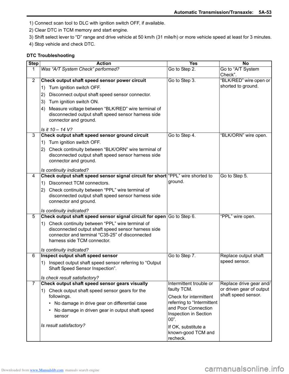
1) Connect scan tool to DLC with ignition switch OFF, if available.
2) Clear DTC in TCM memory and start engine.
3) Shift select lever to “D” range and drive vehicle at 50 km /h (31 mile/h) or more vehicle speed at least for 3 minutes.
4) Stop vehicle and check DTC.
DTC Troubleshooting Step Action Yes No 1 Was “A/T System Check” performed? Go to Step 2. Go to “A/T System
Check”.
2 Check output shaft speed sensor power circuit
1) Turn ignition switch OFF.
2) Disconnect output shaft speed sensor connector.
3) Turn ignition switch ON.
4) Measure voltage between “BLK/RED” wire terminal of
disconnected output shaft speed sensor harness side
connector and ground.
Is it 10 – 14 V? Go to Step 3. “BLK/RED” wire open or
shorted to ground.
3 Check output shaft speed sensor ground circuit
1) Turn ignition switch OFF.
2) Check continuity between “BLK/ORN” wire terminal of
disconnected output shaft speed sensor harness side
connector and ground.
Is continuity indicated? Go to Step 4. “BLK/ORN” wire open.
4 Check output shaft speed sensor signal circuit for short
1) Disconnect TCM connectors.
2) Check continuity between “PPL” wire terminal of
disconnected output shaft speed sensor harness side
connector and ground.
Is continuity indicated? “PPL” wire shorted to
ground.
Go to Step 5.
5 Check output shaft speed sensor signal circuit for open
1) Check continuity between “PPL” wire terminal of
disconnected output shaft speed sensor harness side
connector and terminal “C35-25” of disconnected
harness side TCM connector.
Is continuity indicated? Go to Step 6. “PPL” wire open.
6 Inspect output shaft speed sensor
1) Inspect output shaft speed sensor referring to “Output
Shaft Speed Sensor Inspection”.
Is check result satisfactory? Go to Step 7. Replace output shaft
speed sensor.
7 Check output shaft speed sensor gears visually
1) Check output shaft speed sensor gears for the
followings.
• No damage in drive gear on differential case
• No damage in driven gear in output shaft speed sensor
Is result satisfactory? Intermittent trouble or
faulty TCM.
Check for intermittent
referring to “Intermittent
and Poor Connection
Inspection in Section
00”.
If OK, substitute a
known-good TCM and
recheck.Replace drive gear and/
or driven gear of output
shaft speed sensor.
Page 700 of 1496
Downloaded from www.Manualslib.com manuals search engine 5A-56 Automatic Transmission/Transaxle:
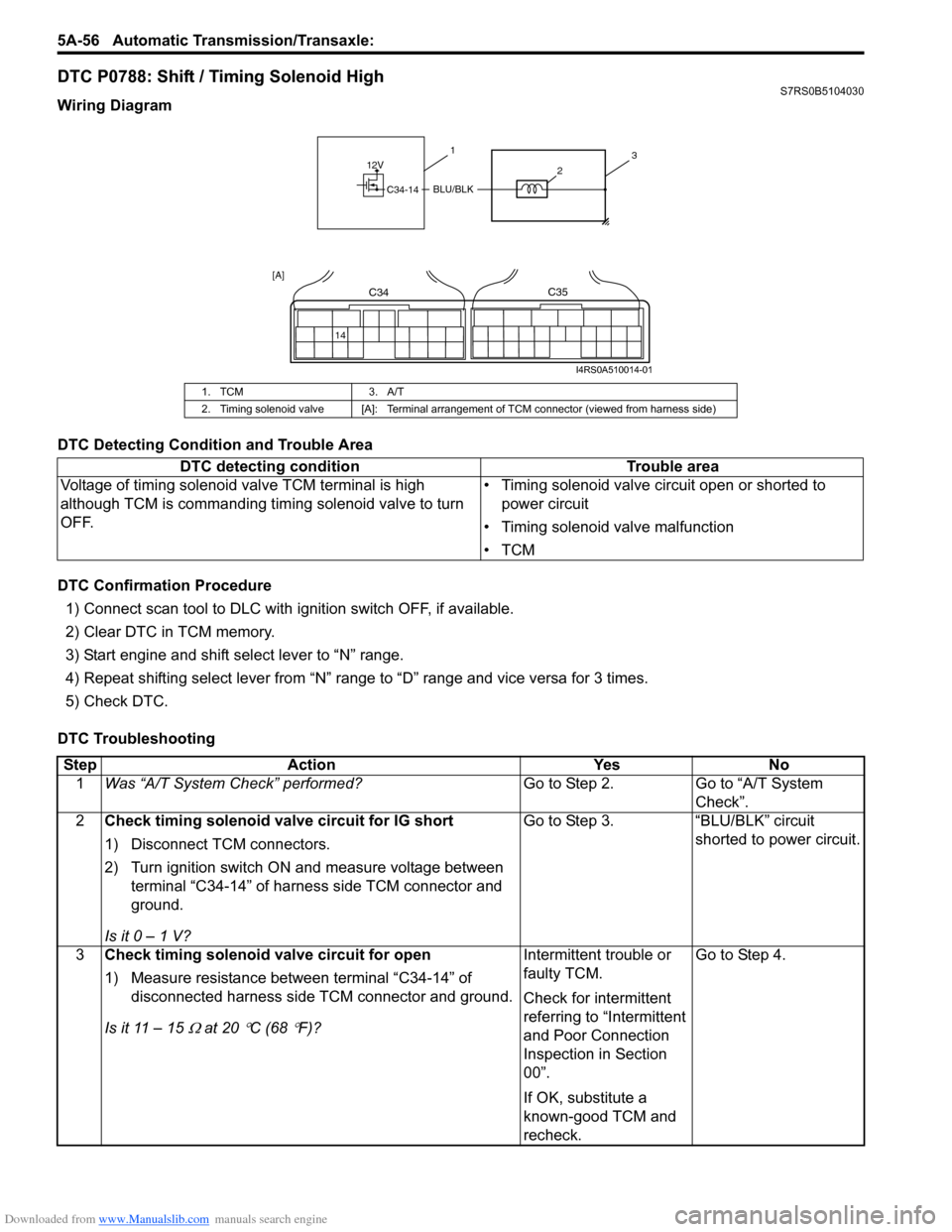
DTC P0788: Shift / Timing Solenoid HighS7RS0B5104030
Wiring Diagram
DTC Detecting Condition and Trouble Area
DTC Confirmation Procedure
1) Connect scan tool to DLC with ig nition switch OFF, if available.
2) Clear DTC in TCM memory.
3) Start engine and shift select lever to “N” range.
4) Repeat shifting select lever from “N” range to “D” range and vice versa for 3 times.
5) Check DTC.
DTC Troubleshooting
1. TCM 3. A/T
2. Timing solenoid valve [A]: Terminal arrangement of TCM connector (viewed from harness side)
DTC detecting condition Trouble area
Voltage of timing solenoid valve TCM terminal is high
although TCM is commanding timing solenoid valve to turn
OFF. • Timing solenoid valve circuit open or shorted to
power circuit
• Timing solenoid valve malfunction
•TCM
12V
C34-14BLU/BLK
31
2
14
C34C35
[A]
I4RS0A510014-01
Step Action YesNo
1 Was “A/T System Check” performed? Go to Step 2.Go to “A/T System
Check”.
2 Check timing solenoid valve circuit for IG short
1) Disconnect TCM connectors.
2) Turn ignition switch ON and measure voltage between
terminal “C34-14” of harness side TCM connector and
ground.
Is it 0 – 1 V? Go to Step 3.
“BLU/BLK” circuit
shorted to power circuit.
3 Check timing solenoid valve circuit for open
1) Measure resistance between terminal “C34-14” of
disconnected harness side TCM connector and ground.
Is it 11 – 15
Ω at 20 °C (68 °F)? Intermittent trouble or
faulty TCM.
Check for intermittent
referring to “Intermittent
and Poor Connection
Inspection in Section
00”.
If OK, substitute a
known-good TCM and
recheck.Go to Step 4.
Page 717 of 1496
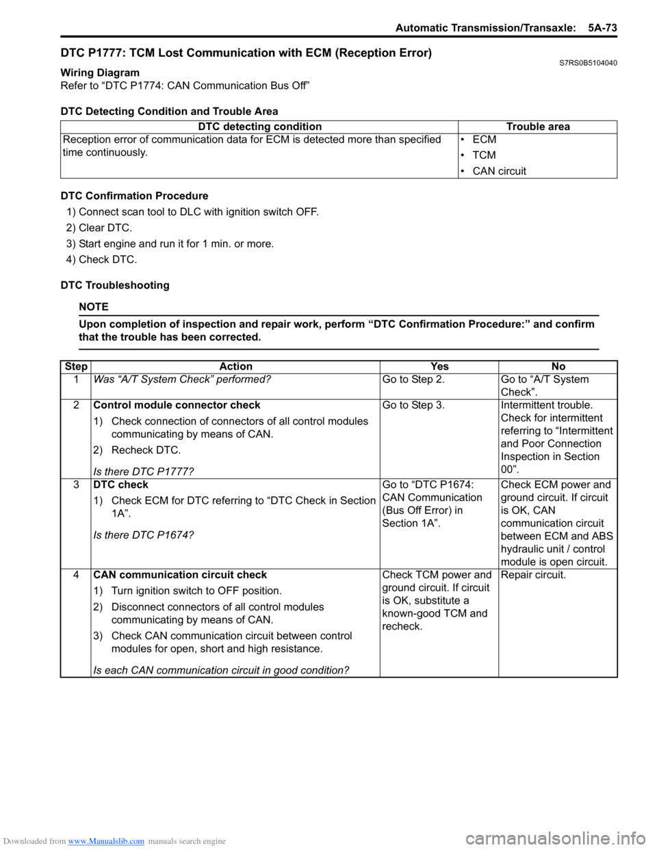
Downloaded from www.Manualslib.com manuals search engine Automatic Transmission/Transaxle: 5A-73
DTC P1777: TCM Lost Communication with ECM (Reception Error)S7RS0B5104040
Wiring Diagram
Refer to “DTC P1774: CAN Communication Bus Off”
DTC Detecting Condition and Trouble Area
DTC Confirmation Procedure1) Connect scan tool to DLC with ignition switch OFF.
2) Clear DTC.
3) Start engine and run it for 1 min. or more.
4) Check DTC.
DTC Troubleshooting
NOTE
Upon completion of inspection and repair work, perform “DTC Confirmation Procedure:” and confirm
that the trouble has been corrected.
DTC detecting condition Trouble area
Reception error of communication data fo r ECM is detected more than specified
time continuously. •ECM
•TCM
• CAN circuit
Step
Action YesNo
1 Was “A/T System Check” performed? Go to Step 2.Go to “A/T System
Check”.
2 Control module connector check
1) Check connection of connectors of all control modules
communicating by means of CAN.
2) Recheck DTC.
Is there DTC P1777? Go to Step 3.
Intermittent trouble.
Check for intermittent
referring to “Intermittent
and Poor Connection
Inspection in Section
00”.
3 DTC check
1) Check ECM for DTC referring to “DTC Check in Section
1A”.
Is there DTC P1674? Go to “DTC P1674:
CAN Communication
(Bus Off Error) in
Section 1A”.
Check ECM power and
ground circuit. If circuit
is OK, CAN
communication circuit
between ECM and ABS
hydraulic unit / control
module is open circuit.
4 CAN communication circuit check
1) Turn ignition switch to OFF position.
2) Disconnect connectors of all control modules
communicating by means of CAN.
3) Check CAN communication circuit between control modules for open, short and high resistance.
Is each CAN communication circuit in good condition? Check TCM power and
ground circuit. If circuit
is OK, substitute a
known-good TCM and
recheck.
Repair circuit.
Page 718 of 1496
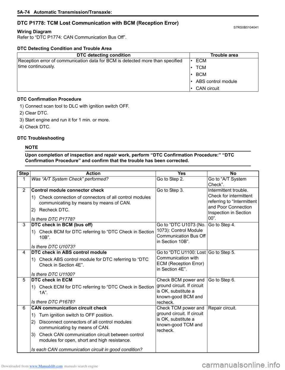
Downloaded from www.Manualslib.com manuals search engine 5A-74 Automatic Transmission/Transaxle:
DTC P1778: TCM Lost Communication with BCM (Reception Error)S7RS0B5104041
Wiring Diagram
Refer to “DTC P1774: CAN Communication Bus Off”.
DTC Detecting Condition and Trouble Area
DTC Confirmation Procedure
1) Connect scan tool to DLC with ignition switch OFF.
2) Clear DTC.
3) Start engine and run it for 1 min. or more.
4) Check DTC.
DTC Troubleshooting
NOTE
Upon completion of inspection and repair work, perform “DTC Confirmation Procedure:” “DTC
Confirmation Procedure” and confirm that the trouble has been corrected.
DTC detecting condition Trouble area
Reception error of communication data fo r BCM is detected more than specified
time continuously. •ECM
•TCM
•BCM
• ABS control module
• CAN circuit
Step
Action YesNo
1 Was “A/T System Check” performed? Go to Step 2.Go to “A/T System
Check”.
2 Control module connector check
1) Check connection of connectors of all control modules
communicating by means by means of CAN.
2) Recheck DTC.
Is there DTC P1778? Go to Step 3.
Intermittent trouble.
Check for intermittent
referring to “Intermittent
and Poor Connection
Inspection in Section
00”.
3 DTC check in BCM (bus off)
1) Check BCM for DTC referring to “DTC Check in Section
10B”.
Is there DTC U1073? Go to “DTC U1073 (No.
1073): Control Module
Communication Bus Off
in Section 10B”.
Go to Step 4.
4 DTC check in ABS control module
1) Check ABS control module for DTC referring to “DTC
Check in Section 4E”.
Is there DTC U1100? Go to “DTC U1100: Lost
Communication with
ECM (Reception Error)
in Section 4E”.
Go to Step 5.
5 DTC check in ECM
1) Check ECM for DTC referring to “DTC Check in Section
1A”.
Is there DTC P1678? Check BCM power and
ground circuit. If circuit
is OK, substitute a
known-good BCM and
recheck.Go to Step 6.
6 CAN communication circuit check
1) Turn ignition switch to OFF position.
2) Disconnect connectors of all control modules
communicating by means of CAN.
3) Check CAN communication circuit between control modules for open, short and high resistance.
Is each CAN communication circuit in good condition? Check TCM power and
ground circuit. If circuit
is OK, substitute a
known-good TCM and
recheck.
Repair circuit.
Page 719 of 1496
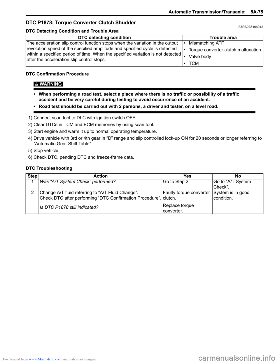
Downloaded from www.Manualslib.com manuals search engine Automatic Transmission/Transaxle: 5A-75
DTC P1878: Torque Converter Clutch ShudderS7RS0B5104042
DTC Detecting Condition and Trouble Area
DTC Confirmation Procedure
WARNING!
• When performing a road test, select a place where there is no traffic or possibility of a traffic accident and be very careful during testing to avoid occurrence of an accident.
• Road test should be carried out with 2 persons, a driver and tester, on a level road.
1) Connect scan tool to DLC with ignition switch OFF.
2) Clear DTCs in TCM and ECM memories by using scan tool.
3) Start engine and warm it up to normal operating temperature.
4) Drive vehicle with 3rd or 4th gear in “D” range and slip c ontrolled lock-up ON for 20 seconds or longer referring to
“Automatic Gear Shift Table”.
5) Stop vehicle.
6) Check DTC, pending DTC and freeze-frame data.
DTC Troubleshooting DTC detecting condition
Trouble area
The acceleration slip control function stops when the variation in the output
revolution speed of the specified amp litude and specified cycle is detected
within a specified period of time. When t he specified variation is not detected
after the acceleration slip control stops. • Mismatching ATF
• Torque converter clutch malfunction
• Valve body
•TCM
Step
Action YesNo
1 Was “A/T System Check” performed? Go to Step 2.Go to “A/T System
Check”.
2 Change A/T fluid referring to “A/T Fluid Change”. Check DTC after performing “DTC Confirmation Procedure”.
Is DTC P1878 still indicated? Faulty torque converter
clutch.
Replace torque
converter.System is in good
condition.
Page 722 of 1496
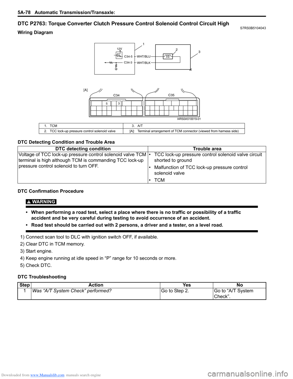
Downloaded from www.Manualslib.com manuals search engine 5A-78 Automatic Transmission/Transaxle:
DTC P2763: Torque Converter Clutch Pressure Control Solenoid Control Circuit HighS7RS0B5104043
Wiring Diagram
DTC Detecting Condition and Trouble Area
DTC Confirmation Procedure
WARNING!
• When performing a road test, select a place where there is no traffic or possibility of a traffic
accident and be very careful during testing to avoid occurrence of an accident.
• Road test should be carried out with 2 persons, a driver and a tester, on a level road.
1) Connect scan tool to DLC with ig nition switch OFF, if available.
2) Clear DTC in TCM memory.
3) Start engine.
4) Keep engine running at idle speed in “P” range for 10 seconds or more.
5) Check DTC.
DTC Troubleshooting
1. TCM 3. A/T
2. TCC lock-up pressure control solenoid valve [A]: Terminal arrangement of TCM connector (viewed from harness side)
DTC detecting conditionTrouble area
Voltage of TCC lock-up pressure control solenoid valve TCM
terminal is high although TCM is commanding TCC lock-up
pressure control sole noid to turn OFF. • TCC lock-up pressure contro
l solenoid valve circuit
shorted to ground
• Malfunction of TCC lock-up pressure control solenoid valve
•TCM
12V
C34-5
C34-3
WHT/BLU
WHT/BLK
3
1
2
53
C34C35
[A]
I4RS0A510019-01
Step
Action YesNo
1 Was “A/T System Check” performed? Go to Step 2.Go to “A/T System
Check”.
Page 724 of 1496
Downloaded from www.Manualslib.com manuals search engine 5A-80 Automatic Transmission/Transaxle:
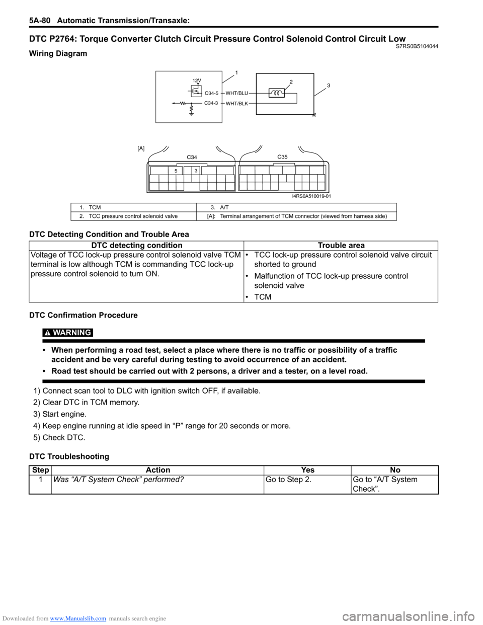
DTC P2764: Torque Converter Clutch Circuit Pressure Control Solenoid Control Circuit LowS7RS0B5104044
Wiring Diagram
DTC Detecting Condition and Trouble Area
DTC Confirmation Procedure
WARNING!
• When performing a road test, select a place where there is no traffic or possibility of a traffic
accident and be very careful during testing to avoid occurrence of an accident.
• Road test should be carried out with 2 persons, a driver and a tester, on a level road.
1) Connect scan tool to DLC with ig nition switch OFF, if available.
2) Clear DTC in TCM memory.
3) Start engine.
4) Keep engine running at idle speed in “P” range for 20 seconds or more.
5) Check DTC.
DTC Troubleshooting
1. TCM 3. A/T
2. TCC pressure control solenoid valve [A]: Terminal arrangement of TCM connector (viewed from harness side)
DTC detecting condition Trouble area
Voltage of TCC lock-up pressure control solenoid valve TCM
terminal is low although TCM is commanding TCC lock-up
pressure control sole noid to turn ON. • TCC lock-up pressure contro
l solenoid valve circuit
shorted to ground
• Malfunction of TCC lock-up pressure control solenoid valve
•TCM
12V
C34-5
C34-3
WHT/BLU
WHT/BLK
3
1
2
53
C34C35
[A]
I4RS0A510019-01
Step
Action YesNo
1 Was “A/T System Check” performed? Go to Step 2.Go to “A/T System
Check”.
Page 739 of 1496
Downloaded from www.Manualslib.com manuals search engine Automatic Transmission/Transaxle: 5A-95
5) Shift select lever to “N” position.
NOTE
If select lever is in “P” position, shift select
lever referring to “Select Lever Inspection”.
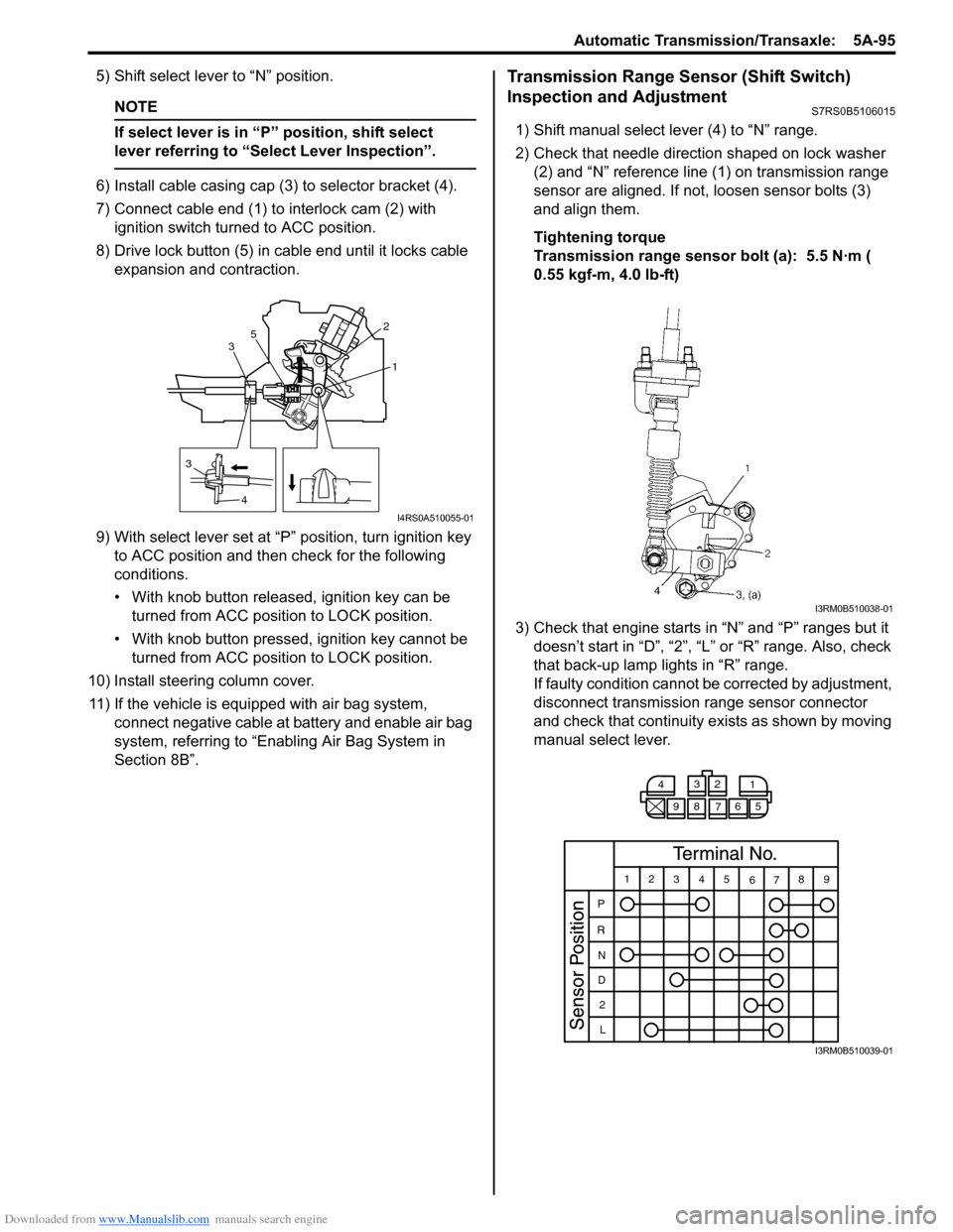
6) Install cable casing cap (3) to selector bracket (4).
7) Connect cable end (1) to interlock cam (2) with ignition switch turned to ACC position.
8) Drive lock button (5) in cable end until it locks cable expansion and contraction.
9) With select lever set at “P ” position, turn ignition key
to ACC position and then check for the following
conditions.
• With knob button released, ignition key can be turned from ACC position to LOCK position.
• With knob button pressed, ignition key cannot be
turned from ACC position to LOCK position.
10) Install steering column cover. 11) If the vehicle is equipped with air bag system, connect negative cable at battery and enable air bag
system, referring to “Enabling Air Bag System in
Section 8B”.
Transmission Range Sensor (Shift Switch)
Inspection and Adjustment
S7RS0B5106015
1) Shift manual select lever (4) to “N” range.
2) Check that needle direction shaped on lock washer (2) and “N” reference line (1) on transmission range
sensor are aligned. If not, loosen sensor bolts (3)
and align them.
Tightening torque
Transmission range sensor bolt (a): 5.5 N·m (
0.55 kgf-m, 4.0 lb-ft)
3) Check that engine starts in “N” and “P” ranges but it doesn’t start in “D”, “2”, “L” or “R” range. Also, check
that back-up lamp lights in “R” range.
If faulty condition cannot be corrected by adjustment,
disconnect transmission range sensor connector
and check that continuity ex ists as shown by moving
manual select lever.
3
4 1
2
3 5
I4RS0A510055-01
I3RM0B510038-01
4
3
2
1
98 76 5
12 345
6789
P
R N
D 2
L
I3RM0B510039-01