ESP SUZUKI SWIFT 2006 2.G Service Workshop Manual
[x] Cancel search | Manufacturer: SUZUKI, Model Year: 2006, Model line: SWIFT, Model: SUZUKI SWIFT 2006 2.GPages: 1496, PDF Size: 34.44 MB
Page 928 of 1496
Downloaded from www.Manualslib.com manuals search engine 6C-46 Power Assisted Steering System:
P/S Control Module Removal and InstallationS7RS0B6306011
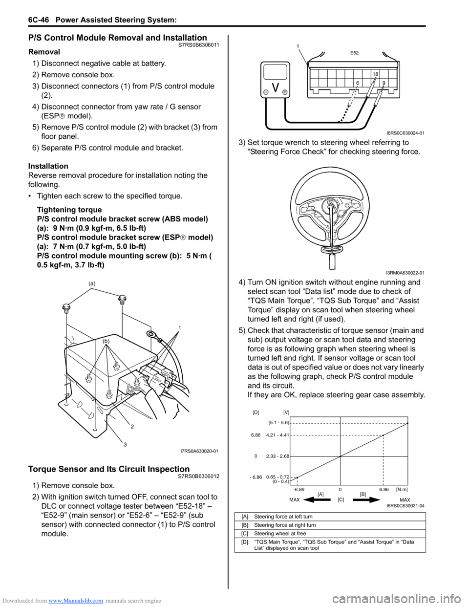
Removal1) Disconnect negative cable at battery.
2) Remove console box.
3) Disconnect connectors (1) from P/S control module (2).
4) Disconnect connector from yaw rate / G sensor
(ESP ® model).
5) Remove P/S control module (2) with bracket (3) from floor panel.
6) Separate P/S control module and bracket.
Installation
Reverse removal procedure for installation noting the
following.
• Tighten each screw to the specified torque. Tightening torque
P/S control module bracket screw (ABS model)
(a): 9 N·m (0.9 kgf-m, 6.5 lb-ft)
P/S control module bracket screw (ESP ® model)
(a): 7 N·m (0.7 kgf-m, 5.0 lb-ft)
P/S control module mounting screw (b): 5 N·m (
0.5 kgf-m, 3.7 lb-ft)
Torque Sensor and Its Circuit InspectionS7RS0B6306012
1) Remove console box.
2) With ignition switch turned OFF, connect scan tool to DLC or connect voltage tester between “E52-18” –
“E52-9” (main sensor) or “E52-6” – “E52-9” (sub
sensor) with connected connector (1) to P/S control
module. 3) Set torque wrench to stee
ring wheel referring to
“Steering Force Check” for checking steering force.
4) Turn ON ignition switch without engine running and select scan tool “Data list” mode due to check of
“TQS Main Torque”, “TQS Sub Torque” and “Assist
Torque” display on scan tool when steering wheel
turned left and right (if used).
5) Check that characteristic of torque sensor (main and sub) output voltage or scan tool data and steering
force is as following graph when steering wheel is
turned left and right. If sensor voltage or scan tool
data is out of specified value or does not vary linearly
as the following graph, check P/S control module
and its circuit.
If they are OK, replace steering gear case assembly.
1
(a)
2
3
(b)
I7RS0A630020-01
[A]: Steering force at left turn
[B]: Steering force at right turn
[C]: Steering wheel at free
[D]: “TQS Main Torque”, “TQS Sub Torque” and “Assist Torque” in “Data List” displayed on scan tool
E52
18
9
6
9
6 18
1
I6RS0C630024-01
I3RM0A630022-01
0
[C] [N.m]
MAX MAX
[B]
[A]
2.33 - 2.68 [V]
[D]
0.65 - 0.72
(0 - 0.4)
4.21 - 4.41
(5.1 - 5.6)
6.86
-6.86
0
6.86
- 6.86
I6RS0C630021-04
Page 930 of 1496
Downloaded from www.Manualslib.com manuals search engine 6C-48 Power Assisted Steering System:
Specifications
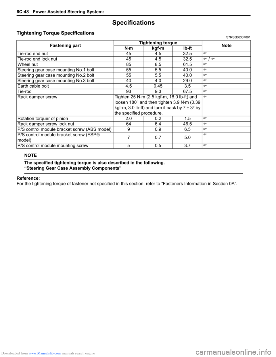
Tightening Torque SpecificationsS7RS0B6307001
NOTE
The specified tightening torque is also described in the following.
“Steering Gear Case Assembly Components”
Reference:
For the tightening torque of fastener not specified in this section, refer to “Fasteners Information in Section 0A”.
Fastening part
Tightening torque
Note
N ⋅mkgf-mlb-ft
Tie-rod end nut 454.5 32.5 �)
Tie-rod end lock nut 454.5 32.5 �) / �)
Wheel nut 858.5 61.5 �)
Steering gear case mounting No.1 bolt 555.5 40.0 �)
Steering gear case mounting No.2 bolt 555.5 40.0 �)
Steering gear case mounting No.3 bolt 404.0 29.0 �)
Earth cable bolt 4.5 0.45 3.5�)
Tie-rod 939.3 67.5 �)
Rack damper screw Tighten 25 N⋅m (2.5 kgf-m, 18.0 lb-ft) and
loosen 180 ° and then tighten 3.9 N ⋅m (0.39
kgf-m, 3.0 lb-ft) and turn it back by 7 ± 3° by
the specified procedure. �)
Rotation torquer of pinion 2.00.2 1.5 �)
Rack damper screw lock nut 646.4 46.5 �)
P/S control module bracket screw (ABS model) 9 0.9 6.5�)
P/S control module bracket screw (ESP ®
model) 70
.7 5 .0 �)
P/S control module mounting screw 50.5 3.7 �)
Page 954 of 1496
Downloaded from www.Manualslib.com manuals search engine 7B-6 Air Conditioning System: Manual Type
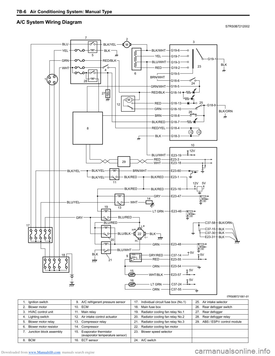
A/C System Wiring DiagramS7RS0B7212002
BLK/REDBLK/RED
BLK/YELBLK/YEL
BLK/YEL
BRN/WHT
12V5V
5V 5V
5V11
E23-1
E23-60
BLK/REDBLK/REDE23-16
E23-57WHT/BLK
9
13
E23-55C37-14GRY/REDRED
BLK
ORN
E23-47 GRY
WHTBLU/YEL
RED/BLK
14 3
1
15
5
7
BLK
2
M
12VBLU/WHTE23-19
C37-24
C37-55ORN
5V
LT GRN16
G18-3
G18-4
G18-7
G18-8
G18-10
G18-13
G18-5
G18-6
G19-5
G19-2
G19-3
G19-7
G19-6
G19-1
G18-9
G18-14
BLK/WHT
YEL
BLU/WHT
RED
BRN/WHT
GRN/WHT
RED/BLK
RED
GRN
BRN
BLK/RED
RED/YEL
BLK
BLK/YEL
BLK/ORN
4
6
12
10
M
E23-54
REDWHTE23-3E23-18
17 18
LT GRNE23-46
L+
L–
H–
H
+
BLU/RED
BLK
BLU/WHTBLK
BLU/BLK
20
GRN
GRY
E23-48
19
21
22
BLU/REDC37-58
C37-15 C37-30
BLK/ORN
BLKBLKE23-31 BLK
BLU
YEL
GRN
WHT
23
24
26 25
28
27
8
29
I7RS0B721001-01
1. Ignition switch
9. A/C refrigerant pressure sensor 17. I ndividual circuit fuse box (No.1) 25. Air intake selector
2. Blower motor 10. ECM 18. Main fuse box 26. Rear defogger switch
3. HVAC control unit 11. Main relay 19. Radiator cooling fan relay No.1 27. Rear defogger
4. Lighting switch 12. Air intake control actuator 20. Radiator cooling fan relay No.2 28. Rear defogger relay
5. Blower motor relay 13. Compressor relay 21. Radiator cooling fan relay No.3 29. ABS / ESP ® control module
6. Blower motor resistor 14. Compressor 22. Radiator cooling fan motor
7. Junction block assembly 15. Evaporator thermistor (evaporator temperature sensor)23. Blower speed selector
8. BCM 16. ECT sensor 24. A/C switch
Page 958 of 1496

Downloaded from www.Manualslib.com manuals search engine 7B-10 Air Conditioning System: Manual Type
Abnormal Noise from Tension Pulley
Abnormal Noise from A/C Evaporator
Abnormal Noise from Blower Motor
A/C System Performance InspectionS7RS0B7214003
1) Confirm that vehicle and environmental conditions are as follows.
• Vehicle is put indoors.
• Ambient temperature is within 25 – 35 °C (77 – 95
° F).
• Relative humidity is within 30 – 70%.
• There is no wind indoors.
• HVAC unit is normal.
• Blower motor is normal.
• There is no air leakage from air ducts.
• Condenser fins are clean.
• Air filter in HVAC unit is not clogged with dirt and
dust.
• Battery voltage is about 12 V.
• Radiator cooling fan operates normally.
2) Make sure that high pressure valve (1) and low pressure valve (2) of manifold gauge are firmly
closed.
3) Connect high pressure charging hose (3) to high pressure service valve (5) on vehicle and low
pressure charging hose (4) to low pressure service
valve (6).
4) Bleed the air in charging hoses (3) and (4) by loosening their nuts respectively utilizing the
refrigerant pressure. When a hissing sound is heard,
immediately tighten nut.
CAUTION!
Do not connect high and low pressure
charging hoses in reverse.
Condition Possible cause Correction / Reference Item
Clattering noise is heard
from pulley Worn or damaged bearing
Replace tension pulley.
Pulley cranks upon
contact Cracked or loose bracket
Replace or retighten bracket.
ConditionPossible cause Correction / Reference Item
Whistling sound is heard
from A/C evaporator Depending on the combination of the
interior / exterior temperatures, engine
rpm and refrigerant pressure, the
refrigerant flowing out of the expansion
valve may, under certain conditions,
make a whistling sound At times, slightly decrea
sing refrigerant volume
may stop this noise.
Inspect expansion valve and replace if faulty.
Condition Possible cause Correction / Reference Item
Blower motor emits a
chirping sound in
proportion to its speed of
rotation Worn or damaged motor brushes or
commutator
Replace blower motor.
Fluttering noise or large
droning noise is heard
from blower motor Leaves or other debris introduced from
fresh air inlet to blower motor
Remove debris and make sure that the screen
at fresh air inlet is intact.
53
2
1
4 6
I4RS0A720006-01
Page 966 of 1496
Downloaded from www.Manualslib.com manuals search engine 7B-18 Air Conditioning System: Manual Type
When replacing other parts
Replenish the following amount of oil to compressor.
Amount of compressor oil to be replenished
Evaporator: 25 cm3 (25 ml, 0.85 US. oz, 0.88 Imp. oz)
Condenser: 15 cm3 (15 ml, 0.51 US. oz, 0.53 Imp. oz)
Receiver/dryer: 10 cm3 (10 ml, 0.34 US. oz, 0.35 lmp.
oz)
Hoses: 10 cm
3 (10 ml, 0.34 US. oz, 0.35 Imp. oz) each
Pipes: 10 cm3 (10 ml, 0.34 US. oz, 0.35 Imp. oz) each
Evacuation
CAUTION!
Do not evacuate before recovering
refrigerant in A/C system.
NOTE
Once air conditioning system circuit is
opened (exposed) to atmospheric air, system
must be evacuated by using a vacuum pump.
The A/C system should be attached with a
manifold gauge set, and should be evacuated
for approximately 15 minutes.
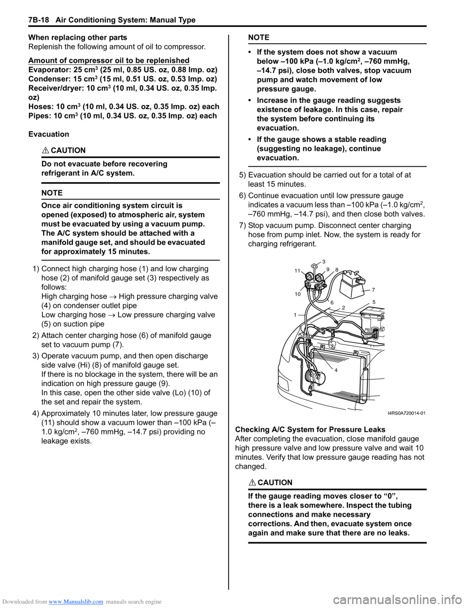
1) Connect high charging hose (1) and low charging hose (2) of manifold gauge set (3) respectively as
follows:
High charging hose → High pressure charging valve
(4) on condenser outlet pipe
Low charging hose → Low pressure charging valve
(5) on suction pipe
2) Attach center charging hose (6) of manifold gauge set to vacuum pump (7).
3) Operate vacuum pump, and then open discharge
side valve (Hi) (8) of manifold gauge set.
If there is no blockage in the system, there will be an
indication on high pressure gauge (9).
In this case, open the other side valve (Lo) (10) of
the set and repair the system.
4) Approximately 10 minutes later, low pressure gauge (11) should show a vacuum lower than –100 kPa (–
1.0 kg/cm
2, –760 mmHg, –14.7 psi) providing no
leakage exists.
NOTE
• If the system does not show a vacuum below –100 kPa (–1.0 kg/cm
2, –760 mmHg,
–14.7 psi), close both valves, stop vacuum
pump and watch movement of low
pressure gauge.
• Increase in the gauge reading suggests existence of leakage. In this case, repair
the system before continuing its
evacuation.
• If the gauge shows a stable reading (suggesting no leakage), continue
evacuation.
5) Evacuation should be carried out for a total of at least 15 minutes.
6) Continue evacuation until low pressure gauge indicates a vacuum less than –100 kPa (–1.0 kg/cm
2,
–760 mmHg, –14.7 psi), and then close both valves.
7) Stop vacuum pump. Disconnect center charging hose from pump inlet. No w, the system is ready for
charging refrigerant.
Checking A/C System for Pressure Leaks
After completing the evacuation, close manifold gauge
high pressure valve and low pressure valve and wait 10
minutes. Verify that low pressure gauge reading has not
changed.
CAUTION!
If the gauge reading moves closer to “0”,
there is a leak somewhere. Inspect the tubing
connections and make necessary
corrections. And then, evacuate system once
again and make sure that there are no leaks.
7 5
2
4
1
10
11
3
9 8
6
I4RS0A720014-01
Page 969 of 1496
Downloaded from www.Manualslib.com manuals search engine Air Conditioning System: Manual Type 7B-21
Removal of Manifold Gauge Set
WARNING!
High pressure side is under high pressure.
Therefore, be careful not to get injured
especially on your eyes and skin.
For the A/C system charged with the specified amount of
refrigerant, remove manifold gauge set as follows:
1) Close low pressure side valve of manifold gauge set. (The high pressure side valve is closed continuously
during the process of charging.)
2) Close refrigerant container valve.
3) Stop engine.
4) Using shop rag, remove charging hoses from service valves. This operation must be performed quickly.
5) Put caps on service valves.
Check A/C System for Refrigerant Leaks
Whenever a refrigerant leak is suspected in the system
or any service operation has been performed which may
result in malfunction of lines and connections, it is
advisable to check for leaks.
Common sense should be used during refrigerant leak
test, since the need and extent of any such test will, in
general, depend upon the nature of a complaint and the
type of a service performed on the system.
Liquid leak detector
WARNING!
• To prevent explosions and fires, make sure that there are no flammables in the vicinity.
• When the refrigerant exposed to fire, it turns into a poisonous gas (phosgene). Do
not inhale this gas.
There is a number of fittings and places throughout the
A/C system where a liquid leak detector solution may be
used to pinpoint refrigerant leaks.
By merely applying the solution to the area in question
with a swab, such as attached to the cap of a vial,
bubbles will form within seconds if there is a leak.
For confined areas, such as sections of the evaporator
and condenser, an electronic (refrigerant) leak detector
is more practical fo r determining leaks.
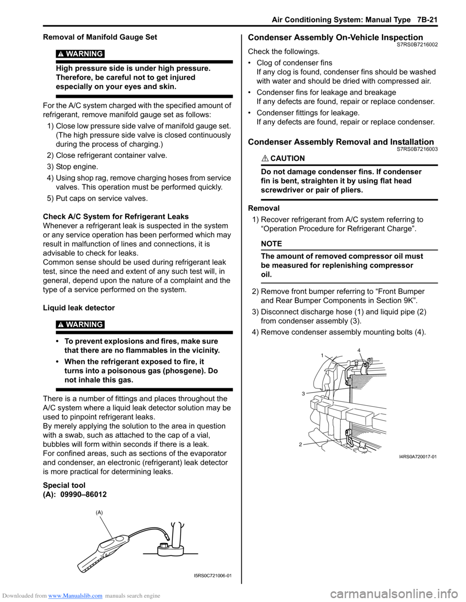
Special tool
(A): 09990–86012
Condenser Assembly On-Vehicle InspectionS7RS0B7216002
Check the followings.
• Clog of condenser fins If any clog is found, cond enser fins should be washed
with water and should be dried with compressed air.
• Condenser fins for leakage and breakage If any defects are found, repair or replace condenser.
• Condenser fittings for leakage. If any defects are found, repair or replace condenser.
Condenser Assembly Removal and InstallationS7RS0B7216003
CAUTION!
Do not damage condenser fins. If condenser
fin is bent, straighten it by using flat head
screwdriver or pair of pliers.
Removal
1) Recover refrigerant from A/C system referring to “Operation Procedure for Refrigerant Charge”.
NOTE
The amount of removed compressor oil must
be measured for replenishing compressor
oil.
2) Remove front bumper referring to “Front Bumper and Rear Bumper Components in Section 9K”.
3) Disconnect discharge hose (1) and liquid pipe (2) from condenser assembly (3).
4) Remove condenser assembly mounting bolts (4).
(A)
I5RS0C721006-01
4
1
3
2
I4RS0A720017-01
Page 977 of 1496
Downloaded from www.Manualslib.com manuals search engine Air Conditioning System: Manual Type 7B-29
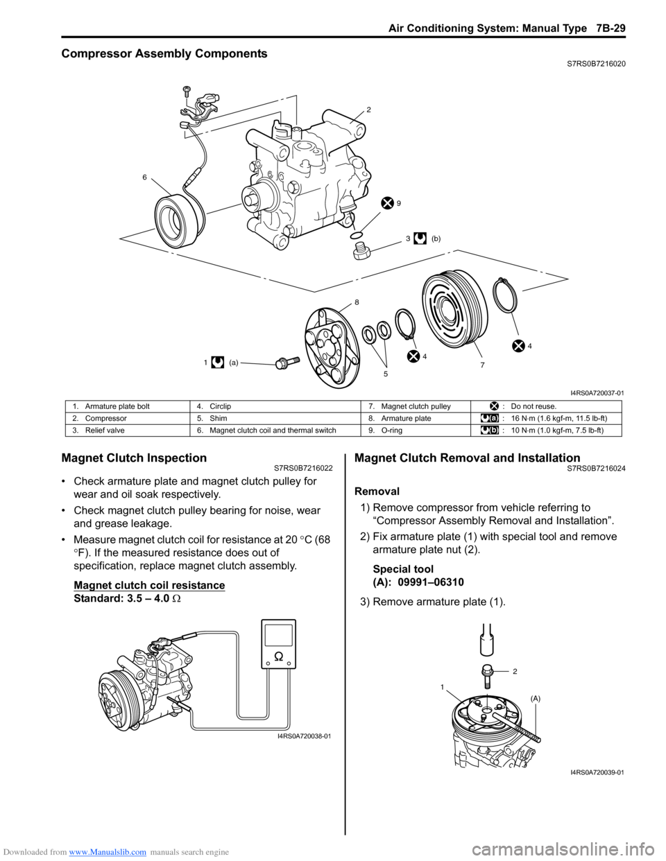
Compressor Assembly ComponentsS7RS0B7216020
Magnet Clutch InspectionS7RS0B7216022
• Check armature plate and magnet clutch pulley for wear and oil soak respectively.
• Check magnet clutch pulley bearing for noise, wear and grease leakage.
• Measure magnet clutch coil for resistance at 20 °C (68
° F). If the measured resistance does out of
specification, replace magnet clutch assembly.
Magnet clutch coil resistance
Standard: 3.5 – 4.0 Ω
Magnet Clutch Removal and InstallationS7RS0B7216024
Removal
1) Remove compressor from vehicle referring to “Compressor Assembly Re moval and Installation”.
2) Fix armature plate (1) with special tool and remove armature plate nut (2).
Special tool
(A): 09991–06310
3) Remove armature plate (1).
6
2
9
44
3 (b)
1 (a) 7
5
8
I4RS0A720037-01
1. Armature plate bolt
4. Circlip 7. Magnet clutch pulley: Do not reuse.
2. Compressor 5. Shim 8. Armature plate: 16 N⋅m (1.6 kgf-m, 11.5 lb-ft)
3. Relief valve 6. Magnet clutch coil and thermal switch 9. O-ring : 10 N⋅m (1.0 kgf-m, 7.5 lb-ft)
I4RS0A720038-01
2
1 (A)
I4RS0A720039-01
Page 982 of 1496
Downloaded from www.Manualslib.com manuals search engine 7B-34 Air Conditioning System: Automatic Type
Automatic Type
Precautions
A/C System CautionS7RS0B7220001
Refer to “A/C System Caution”.
Precautions in Diagnosing TroubleS7RS0B7220002
• Do not disconnect couplers from HVAC control module, battery cable from battery, HVAC control module ground
wire harness from body or main fuse before confirming diagnostic information (diagnostic trouble code) stored in
HVAC control module memory.
• Diagnostic information (diagnostic trouble code) stored in HVAC control module can be checked by display of HVAC
control module. Also, it can be checked by using SU ZUKI scan tool. Before checking diagnostic information
(diagnostic trouble code), read this manual and operator's manual for SUZUKI scan tool to know how to read
diagnostic information (diagnostic trouble code).
• When trouble is diagnosed using diagnostic information (diagnostic trouble code) on display of HVAC control
module, keep in your mind that each diagnostic inform ation (diagnostic trouble code) has priority, and only
diagnostic information (diagnostic troub le code) which has the highest priority is indicated. Therefore, after
troubleshooting the malfunction, make sure if there exists any other diagnostic information (diagnostic trouble
code).
• Be sure to read “Precautions for Electrical Circuit Service in Section 00” before inspection.
Precautions on Servicing A/C SystemS7RS0B7220003
Refer to “Precautions on Servicing A/C System”.
General Description
Auto A/C System DescriptionS7RS0B7221001
The automatic type air conditioning system (auto A/C) is pr ovided with the function to automatically control the inside
air temperature, fan speed, air flow outl et direction and air intake position by HVAC control module in addition to
functions of the manual type air conditioning system (manua l A/C). Once the inside air temperature is set using the
temperature selector, HVAC control module automatically controls the inside air temperature at the constant level at all
times based on the inside air temperature, outside ai r temperature, amount of sunlight and engine coolant
temperature detected respectively by the inside air te mperature sensor, outside air temperature sensor, sunload
sensor and ECT sensor. At this time, “FULL AUTO A/ C” appears on the display of HVAC control module.
With the air intake selector pushed in the above state, it is possible to select any position of the air intake actuator.
Then, “FULL AUTO A/C” on the display changes to “AUTO A/C”.
Page 1039 of 1496
Downloaded from www.Manualslib.com manuals search engine Air Bag System: 8B-1
Restraint
Air Bag System
Precautions
Precautions on Service and Diagnosis of Air
Bag System
S7RS0B8200001
WARNING!
• If the air bag system and another vehicle system both need repair, SUZUKI
recommends that the air bag system be
repaired first, to help avoid unintended air
bag system activation.
• Do not modify the steering wheel, dashboard, both front seat or any other on
or around air bag system components.
Modifications can adversely affect air bag
system performance and lead to injury.
• Be sure to follow the procedures described in this section. Failure to follow
procedures could result in possible air bag
system activation, personal injury or
unneeded air bag system repairs.
• WARNING / CAUTION labels are attached on each
part of air bag system components (SDM, air bag
(inflator) modules and seat belt pretensioners). Be
sure to follow the instructions.
• Many of service procedures require disconnection of
“A/BAG” fuse and air bag (inflator) module(s) (driver,
passenger, side of both si des and curtain of both
sides) from initiator circuit to avoid an accidental
deployment.
• Do not apply power to the air bag system unless all components are connected or a diagnostic flow
requests it, as this will set a DTC.
• The “Air Bag Diagnostic S ystem Check” must be the
starting point of any air bag diagnostics. The “Air Bag
Diagnostic System Check” will verify proper “AIR
BAG” warning right operatio n and will lead you to the
correct flow to diagnose any air bag malfunctions.
Bypassing these procedures may result in extended
diagnostic time, incorrect diagnosis, and incorrect
parts replacements. • Never use air bag component parts from another
vehicle.
• If the vehicle will be exposed to temperatures over 93
° C (200 °F) (for example, during a paint baking
process), remove the air bag system components
beforehand to avoid component damage or
unintended system activation.
• When handling the air bag (inflator) modules (driver, passenger, side of both si des and curtain of both
sides), seat belt pretensio ners (driver and passenger),
SDM, forward-sensor or side-sensor, be careful not to
drop it or apply an impact to it. If an excessive impact
was applied (e.g., SDM, forward-sensor and side-
sensor are dropped, air bag (inflator) module is
dropped from a height of 90 cm (3 ft) or more, seat
belt pretensioner (retractor assembly) is dropped from
a height of 30 cm (1 ft) or more), never attempt
disassembly or repair but replace it with a new one.
• When using electric welding, be sure to disconnect air bag (inflator) module connectors (driver, passenger,
side of both sides and curtain of both sides) and seat
belt pretensioner connectors (driver and passenger)
respectively.
• When applying paint around the air bag system related parts, use care so that the harness or
connector will not be expo sed to the paint mist.
• Never expose air bag system component parts directly to hot air (drying or baking the vehicle after
painting) or flames.
WARNING!
When performing service on or around air
bag system components or air bag wiring,
follow the procedures listed in “Disabling Air
Bag System” to temporarily disable the air
bag system.
Failure to follow procedures could result in
possible air bag system activation, personal
injury or unneeded air bag system repairs.
Page 1049 of 1496
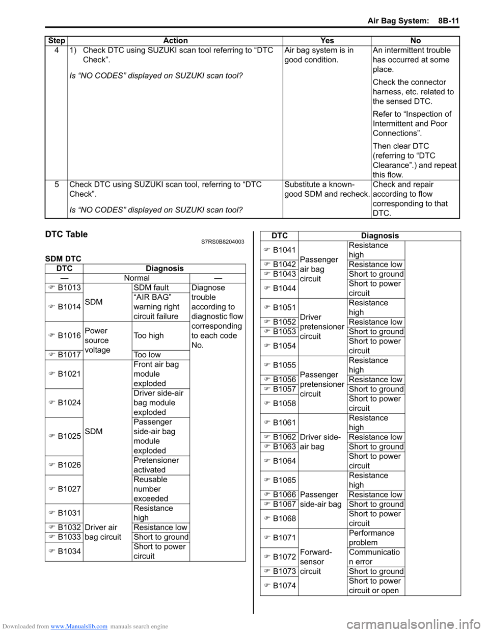
Downloaded from www.Manualslib.com manuals search engine Air Bag System: 8B-11
DTC TableS7RS0B8204003
SDM DTC4 1) Check DTC using SUZUKI scan tool referring to “DTC
Check”.
Is “NO CODES” displayed on SUZUKI scan tool? Air bag system is in
good condition.
An intermittent trouble
has occurred at some
place.
Check the connector
harness, etc. related to
the sensed DTC.
Refer to “Inspection of
Intermittent and Poor
Connections”.
Then clear DTC
(referring to “DTC
Clearance”.) and repeat
this flow.
5 Check DTC using SUZUKI scan tool, referring to “DTC Check”.
Is “NO CODES” displayed on SUZUKI scan tool? Substitute a known-
good SDM and recheck.
Check and repair
according to flow
corresponding to that
DTC.
Step Action Yes No
DTC
Diagnosis
—N orm al —
�) B1013
SDM SDM fault Diagnose
trouble
according to
diagnostic flow
corresponding
to each code
No.
�)
B1014 “AIR BAG”
warning right
circuit failure
�) B1016 Power
source
voltage Too high
�) B1017 Too low
�) B1021
SDM Front air bag
module
exploded
�) B1024 Driver side-air
bag module
exploded
�) B1025 Passenger
side-air bag
module
exploded
�) B1026 Pretensioner
activated
�) B1027 Reusable
number
exceeded
�) B1031
Driver air
bag circuit Resistance
high
�) B1032 Resistance low
�) B1033 Short to ground
�) B1034 Short to power
circuit
�)
B1041
Passenger
air bag
circuit Resistance
high
�) B1042 Resistance low
�) B1043 Short to ground
�) B1044 Short to power
circuit
�) B1051
Driver
pretensioner
circuit Resistance
high
�) B1052 Resistance low
�) B1053 Short to ground
�) B1054 Short to power
circuit
�) B1055
Passenger
pretensioner
circuit Resistance
high
�) B1056 Resistance low
�) B1057 Short to ground
�) B1058 Short to power
circuit
�) B1061
Driver side-
air bag Resistance
high
�) B1062 Resistance low
�) B1063 Short to ground
�) B1064 Short to power
circuit
�) B1065
Passenger
side-air bag Resistance
high
�) B1066 Resistance low
�) B1067 Short to ground
�) B1068 Short to power
circuit
�) B1071
Forward-
sensor
circuit Performance
problem
�) B1072 Communicatio
n error
�) B1073 Short to ground
�) B1074 Short to power
circuit or open
DTC Diagnosis