510 SUZUKI SWIFT 2006 2.G Service Workshop Manual
[x] Cancel search | Manufacturer: SUZUKI, Model Year: 2006, Model line: SWIFT, Model: SUZUKI SWIFT 2006 2.GPages: 1496, PDF Size: 34.44 MB
Page 1156 of 1496
Downloaded from www.Manualslib.com manuals search engine 8B-118 Air Bag System:
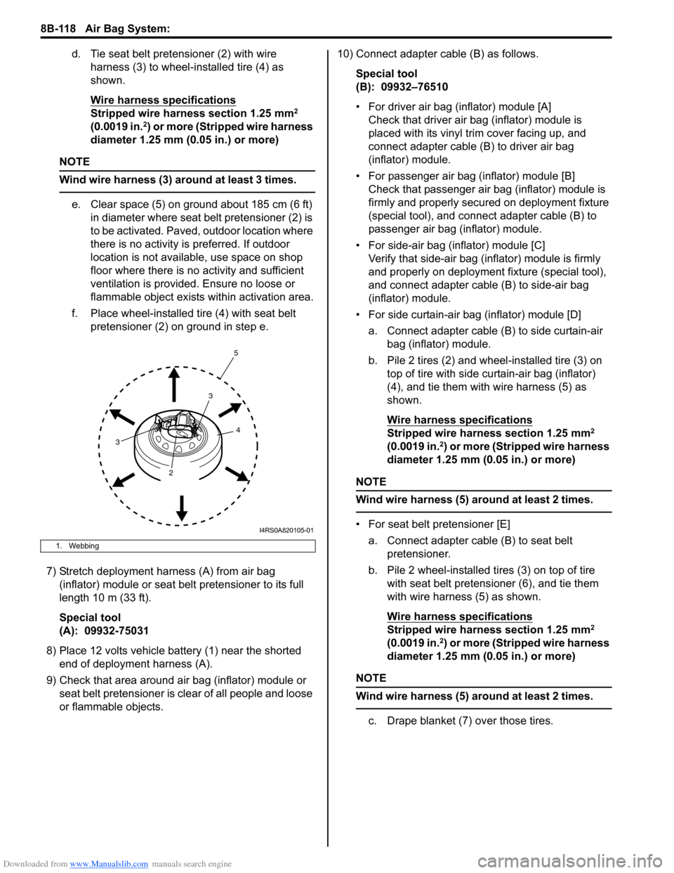
d. Tie seat belt pretensioner (2) with wire harness (3) to wheel-installed tire (4) as
shown.
Wire harness specifications
Stripped wire harness section 1.25 mm2
(0.0019 in.2) or more (Stripped wire harness
diameter 1.25 mm (0.05 in.) or more)
NOTE
Wind wire harness (3) around at least 3 times.
e. Clear space (5) on ground about 185 cm (6 ft) in diameter where seat belt pretensioner (2) is
to be activated. Paved, outdoor location where
there is no activity is preferred. If outdoor
location is not available, use space on shop
floor where there is no activity and sufficient
ventilation is provided. Ensure no loose or
flammable object exists within activation area.
f. Place wheel-installed tire (4) with seat belt pretensioner (2) on ground in step e.
7) Stretch deployment harness (A) from air bag (inflator) module or seat belt pretensioner to its full
length 10 m (33 ft).
Special tool
(A): 09932-75031
8) Place 12 volts vehicle battery (1) near the shorted end of deployment harness (A).
9) Check that area around air bag (inflator) module or seat belt pretensioner is clear of all people and loose
or flammable objects. 10) Connect adapter cable (B) as follows.
Special tool
(B): 09932–76510
• For driver air bag (inflator) module [A]Check that driver air bag (inflator) module is
placed with its vinyl trim cover facing up, and
connect adapter cable (B) to driver air bag
(inflator) module.
• For passenger air bag (inflator) module [B] Check that passenger air bag (inflator) module is
firmly and properly secured on deployment fixture
(special tool), and connect adapter cable (B) to
passenger air bag (inflator) module.
• For side-air bag (inflator) module [C] Verify that side-air bag (inflator) module is firmly
and properly on deployment fixture (special tool),
and connect adapter cable (B) to side-air bag
(inflator) module.
• For side curtain-air bag (inflator) module [D] a. Connect adapter cable (B) to side curtain-air bag (inflator) module.
b. Pile 2 tires (2) and wheel-installed tire (3) on top of tire with side curtain-air bag (inflator)
(4), and tie them with wire harness (5) as
shown.
Wire harness specifications
Stripped wire harness section 1.25 mm2
(0.0019 in.2) or more (Stripped wire harness
diameter 1.25 mm (0.05 in.) or more)
NOTE
Wind wire harness (5) around at least 2 times.
• For seat belt pretensioner [E]
a. Connect adapter cable (B) to seat belt pretensioner.
b. Pile 2 wheel-installed tires (3) on top of tire with seat belt pretensioner (6), and tie them
with wire harness (5) as shown.
Wire harness specifications
Stripped wire harness section 1.25 mm2
(0.0019 in.2) or more (Stripped wire harness
diameter 1.25 mm (0.05 in.) or more)
NOTE
Wind wire harness (5) around at least 2 times.
c. Drape blanket (7) over those tires.
1. Webbing
4
3
3 2 5
I4RS0A820105-01
Page 1160 of 1496
Downloaded from www.Manualslib.com manuals search engine 8B-122 Air Bag System:
5) Check that there is no open, short or damage in special tools (deployment harness (A), adapter cable
(B) and (C)). If any faulty condition is found, do not
use it and be sure to use new special tool. And
connect adapter cable (B), (C) or (D) to deployment
harness (A) and lock connectors with lock slider.
Special tool
(A): 09932-75031
(B): 09932–77310
(C): 09932–78332
(D): 09932–76510
6) Short two deployment harness leads together by fully seating one banana plug into the other.
WARNING!
Deployment harness (A) shall remain shorted
and not be connected to 12 volts vehicle
battery until you are ready to deploy air bag
(inflator) module or activate seat belt
pretensioner.
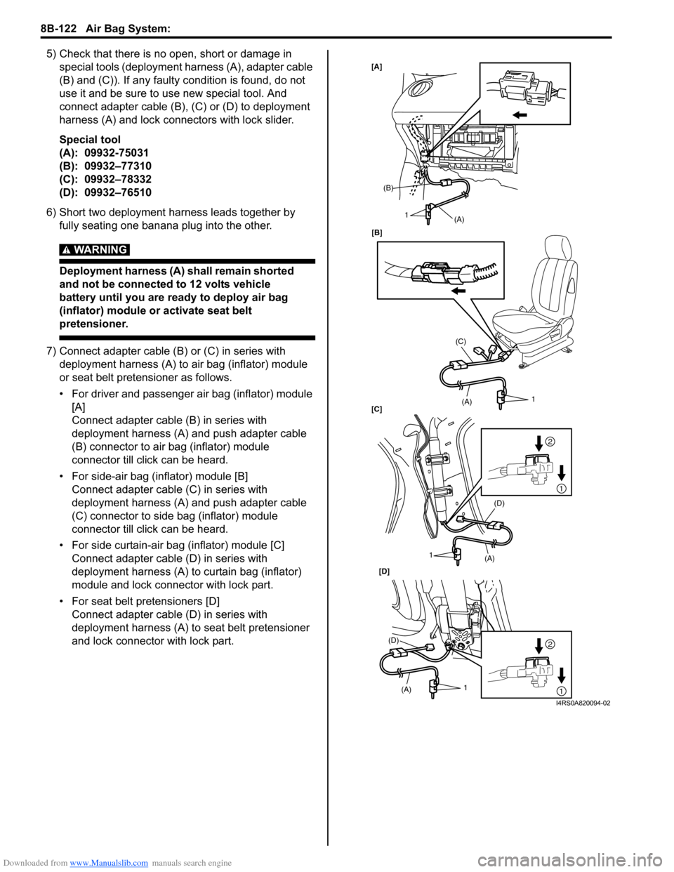
7) Connect adapter cable (B) or (C) in series with deployment harness (A) to air bag (inflator) module
or seat belt pretensioner as follows.
• For driver and passenger air bag (inflator) module [A]
Connect adapter cable (B) in series with
deployment harness (A) and push adapter cable
(B) connector to air bag (inflator) module
connector till click can be heard.
• For side-air bag (inflator) module [B] Connect adapter cable (C) in series with
deployment harness (A) and push adapter cable
(C) connector to side bag (inflator) module
connector till click can be heard.
• For side curtain-air bag (inflator) module [C] Connect adapter cable (D) in series with
deployment harness (A) to curtain bag (inflator)
module and lock connector with lock part.
• For seat belt pretensioners [D] Connect adapter cable (D) in series with
deployment harness (A) to seat belt pretensioner
and lock connector with lock part.
[A]
[C]
[D]
1
2
1
2
1
(B) (A)
[B]
1
(C)
(A)
1
(D)
(A)
(A)
(D)
1
I4RS0A820094-02
Page 1165 of 1496
Downloaded from www.Manualslib.com manuals search engine Air Bag System: 8B-127
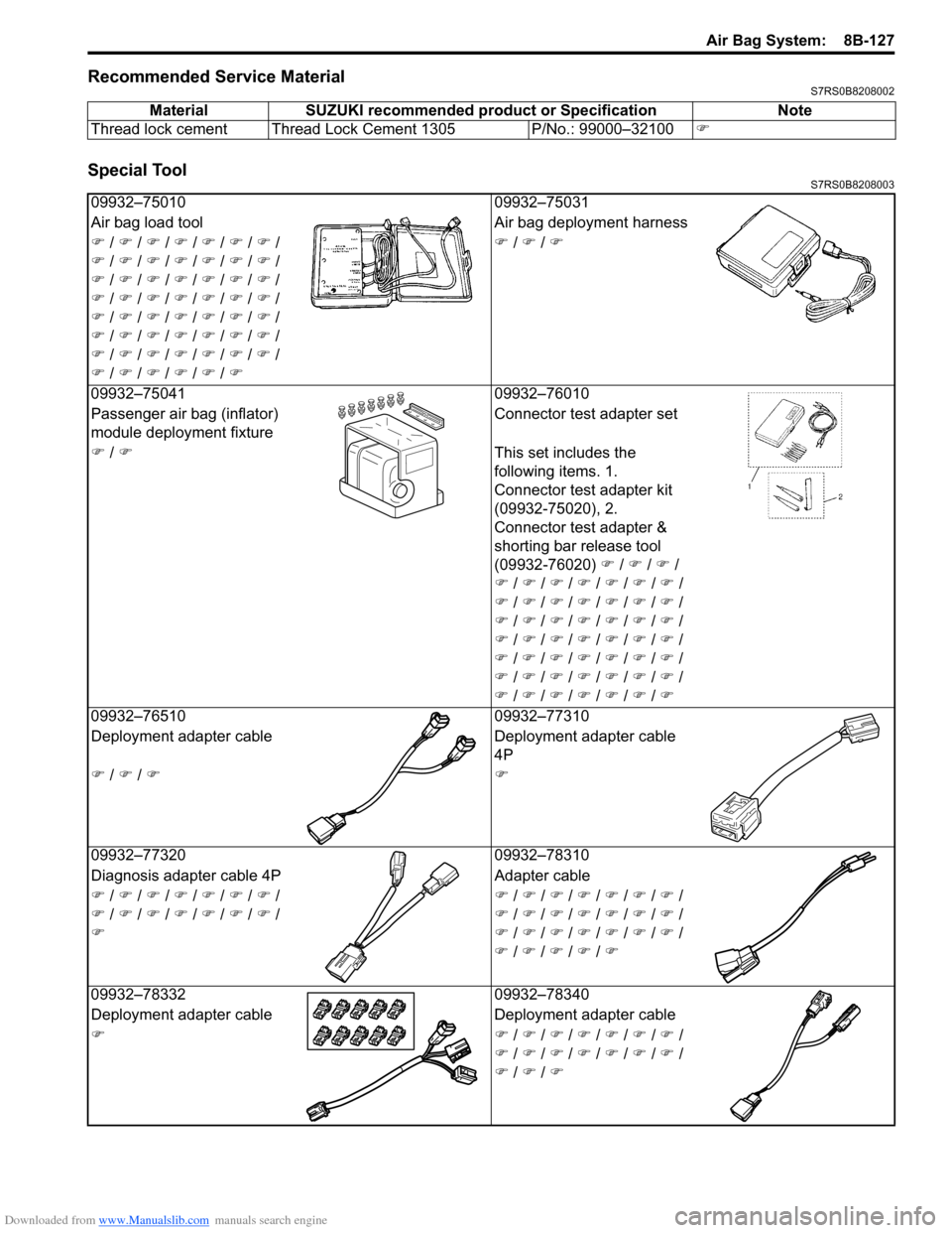
Recommended Service MaterialS7RS0B8208002
Special ToolS7RS0B8208003
MaterialSUZUKI recommended product or Specification Note
Thread lock cement Thread Lock Cement 1305 P/No.: 99000–32100 �)
09932–7501009932–75031
Air bag load tool Air bag deployment harness
�) / �) / �) / �) / �) / �) / �) /
�) / �) / �) / �) / �) / �) / �) /
�) / �) / �) / �) / �) / �) / �) /
�) / �) / �) / �) / �) / �) / �) /
�) / �) / �) / �) / �) / �) / �) /
�) / �) / �) / �) / �) / �) / �) /
�) / �) / �) / �) / �) / �) / �) /
�) / �) / �) / �) / �) / �) �)
/ �) / �)
0
9932–75041 09932–76010
Passenger air bag (inflator)
module deployment fixture Connector test adapter set
�) / �) This set includes the
following items. 1.
Connector test adapter kit
(09932-75020), 2.
Connector test adapter &
shorting bar release tool
(09932-76020) �) / �) / �) /
�) / �) / �) / �) / �) / �) / �) /
�) / �) / �) / �) / �) / �) / �) /
�) / �) / �) / �) / �) / �) / �) /
�) / �) / �) / �) / �) / �) / �) /
�) / �) / �) / �) / �) / �) / �) /
�) / �) / �) / �) / �) / �) / �) /
�) / �) / �) / �) / �) / �) / �)
0
9932–76510 09932–77310
Deployment adapter cable Deployment adapter cable
4P
�) / �) / �)�)
09932–77320 09932–78310
Diagnosis adapter cable 4P Adapter cable
�) / �) / �) / �) / �) / �) / �) /
�) / �) / �) / �) / �) / �) / �) /
�) �)
/ �) / �) / �) / �) / �) / �) /
�) / �) / �) / �) / �) / �) / �) /
�) / �) / �) / �) / �) / �) / �) /
�) / �) / �) / �) / �)
0
9932–78332 09932–78340
Deployment adapter cable Deployment adapter cable
�)�) / �) / �) / �) / �) / �) / �) /
�) / �) / �) / �) / �) / �) / �) /
�) / �) / �)
Page 1210 of 1496
Downloaded from www.Manualslib.com manuals search engine 9A-39 Wiring Systems:
1IG2FL2
6
Lamp FL (FL BOX)
1A/B CONT4A/B SIG
3K-LINE2A/B SIGNAL
9A/B SIGNAL8K-LINE
2311BCM ;IG1
22D/UL-IN21D/L-IN D/SL-IN
18SECURITY IN6Serial OUT
14TAIL BCM WNG, etc12ANSWER BACK
17RR DEF CONTROL1D/L (+B)
2BCM15DEICER CONTROL
10ACC (BCM)7DOME LP CONT
20GND (POWER)16R-WIP (CONT)
3SIGNAL GND (BCM)
7IG
1LP-L5LP-R
8+B6SW-L
3GND4SW-R
2HAZ
DOME LP POWER5DOME LP DOOR4*3GND (Roof)6HTR4Starter SW1IG 25ACC SW3IG2SW2IG 1
18107G33415G347G3419G341G3412G339G3311G343G342G348G34166G336G345G33810511G3313G344G341G3320G342G339G343G3312G3414G34
10E395E4112E419E4114E411E418E412E4111E413E416E395E3916E417E414E392E399E393E397E3910E41
DEF LP
RR FOG SW DEICER LP
*TAIL SW (Upper)
TAIL SW (HAZ,ASH,ILL) TURN-L
TURN-R
METER (L)
METER (R)
HAZARD SW HORN SW
Serial INF DISP
A/C PANEL
*MTR Power,etc
IMMOBI IG
A/C PANEL
*
*
RADIO, CLOCK
A/B SIGCIGAR
*F-WIP*
*GND (IP)
SIGNAL GND (IP)
*
*
*
IG Coil, etc EPS AT
ABS CONT
BACK (SHIFT) STOP SW
ABS CONT EPI
BUL IN
HORN
FR TURN (R)
FR TURN (L) POSI LP
EPI
DEICER
*F-Washer
F.WIP
HTR Fuse (30A)
ST RLY COIL
4L0515L0516L055L059L05212L0513L0614L067L0615L0614L0511L056L065L068L057L056L0518L053L051L0510L059L0610L061L063L062L068L0611L064L06
SIGNAL GND (FL)
SEAT HEATER
P/W
R-WIP (+) R-WIP (-)*
ACC SOCKET
R/C MIR (ACC)
*
*
*
LUGGAGE LAMPMTA SHIFT LEVER SW
*
*
RR DEF
HTR MIR (L)
HTR MIR (R)
P/W DR
TAIL LP, LICENSE
R-TURN (L)
RR-TURN (R)
D/ULD/L
D-SL
BUL-L
STOP LP
MTA
*
*
IG COIL 15AMETER 10A A/BAG 15A
IG1 SIG 10A ABS 10A
BACK 10A
TAIL 10AD/L 20A
P/WT 20A
RR DEF 20A
DEICER/RR FOG 15A
MTA/HID R 10A
ACC 1 15A
ACC 2 15A
WIPER 15A P/W 30A
*Spare-1
SEAT HTR 15A IG2 SIG 10AST SIG 10A
HAZ-HORN 15A
DIESEL/HID L 10A *Spare-2 RR DEF RLY
DEICER RLY HORN RLY
P-WIP RLY
BLOWER MOTOR RLY
G34 G34
G33
G34
G33
G34 G33
L05
RADIO 15A
To instrument panel harness
(G32) To roof harness
(K01)
To instrument panel
harness
(G33 , G34 )
To main harness
(E39 , E41) To floor harness (L05 , L06 ) To main
harness
(E40)
BCM
To flasher
relay To floor
harness
(L04)
* : Not used
I7RS0B910949-01
Page 1254 of 1496
Downloaded from www.Manualslib.com manuals search engine 9A-83 Wiring Systems:
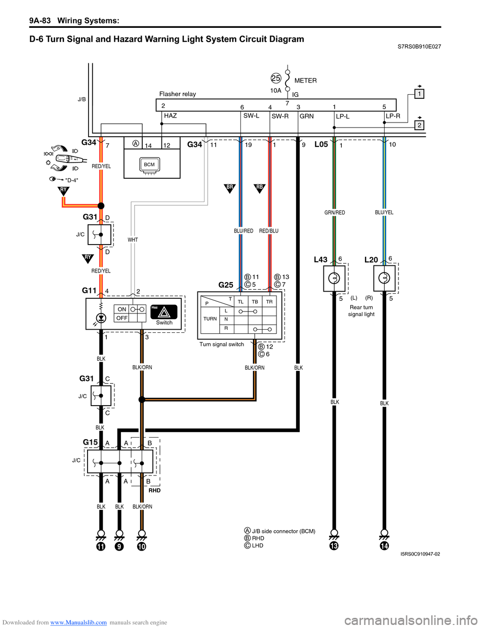
D-6 Turn Signal and Hazard Warning Light System Circuit DiagramS7RS0B910E027
4 D
DG11G312
Switch
BLK/ORNBLK
WHT
Rear turn
signal light
6L43
BLK
11
2
HAZ LP-LLP-R
Flasher relayG34
RED/YEL
RED/YEL
Turn signal switch
G25
10A
METER
25
RED/BLUBLU/RED
J/B
L
N
R
TURN T
P TB
TL TR
J/C
1110
7G3414A
BCM
12
1
BLK
C
CG31
J/C
ON
OFF
3
A
B
A
AG15
J/C
BLU/YEL
(R)
1
1314
BLK
191L0510
IG
7
6
SW-L SW-R
4
BLK
BLK/ORNBLK/ORN
GRN/RED
(L)
L20
5
6
5
1
2
15
RY
9
GRN
3
BLK
B
RY
"D-4"BRRB
BLK
9
A
J/B side connector (BCM)
RHD
LHD
ABC
BC11
5
BC12
6
BC13
7
RHD
I5RS0C910947-02
Page 1267 of 1496
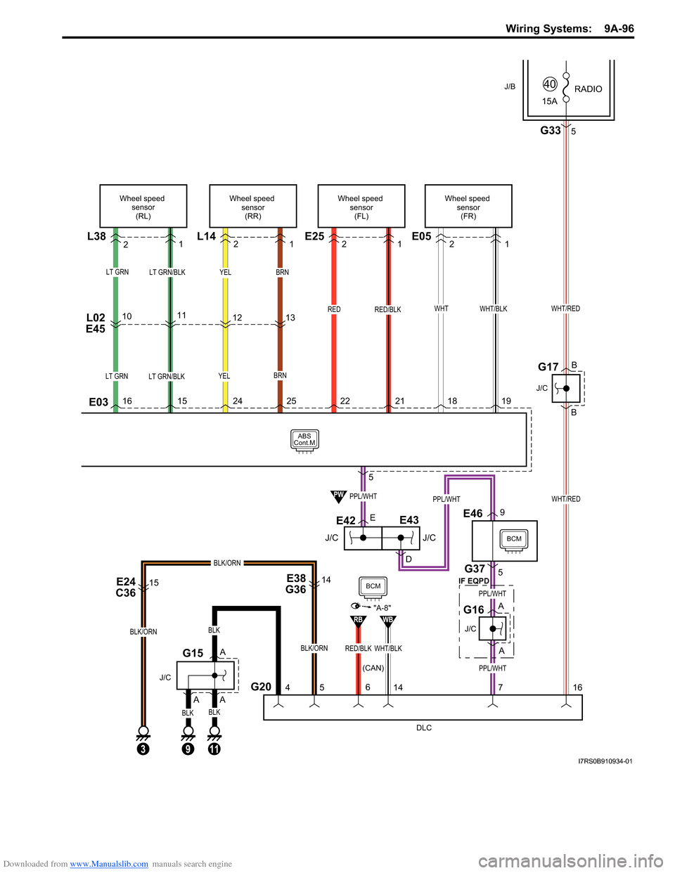
Downloaded from www.Manualslib.com manuals search engine Wiring Systems: 9A-96
YEL
ABS
Cont.M
L38
LT GRN/BLKLT GRN
LT GRN/BLKLT GRN
L02
E451011
Wheel speed
sensor(RL)
BRN
YELBRN
13
12
L14
Wheel speed
sensor(RR)
WHT/BLK
E05
Wheel speed sensor(FR)
WHTRED
E25
Wheel speed sensor(FL)
RED/BLK
E03
2 12 12 121
5
DLC
PPL/WHT
PPL/WHT
A
A
E38
G36
5
E42
D
J/C
G16
PPL/WHT
E
59E46
BCM
BCMPPL/WHT
WHT/RED
G20 G37
PW
WHT/BLKRED/BLK
RBWB
"A-8"
11
BLK
BLK
A
A
J/C
G15
4
E24
C3615
BLK/ORN
3
BLK/ORN
9
BLK
A
B
B
J/C
G17
15A RADIO
40
G335
WHT/RED
J/B
BLK/ORN
14
6
716
14
E43
J/C
J/C
(CAN) IF EQPD
16
15 24 25 22 21 18 19
I7RS0B910934-01
Page 1269 of 1496
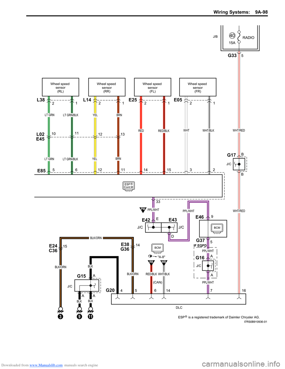
Downloaded from www.Manualslib.com manuals search engine Wiring Systems: 9A-98
YEL
ESP
Cont.M
L38
LT GRN/BLKLT GRN
LT GRN/BLKLT GRN
L02
E4510
5 6 12 11 14 15 3 211
Wheel speed sensor(RL)
BRN
YELBRN
13
12
L14
Wheel speed
sensor(RR)
WHT/BLK
E05
Wheel speed sensor(FR)
WHTRED
E25
Wheel speed sensor(FL)
RED/BLK
E85
2 12 12 121
33
DLC
PPL/WHT
PPL/WHT
A
A
E38
G36
5
E42
D
J/C
G16
PPL/WHT
E
59E46
BCM
BCMPPL/WHT
WHT/RED
G20 G37
PW
WHT/BLKRED/BLK
RBWB
"A-8"
11
BLK
BLK
A
A
J/C
G15
4
E24
C3615
BLK/ORN
3
BLK/ORN
9
BLK
A
B
B
J/C
G17
15A RADIO
40
G335
WHT/RED
J/B
BLK/ORN
14
6
716
14
E43
J/C
J/C
(CAN) IF EQPD
R
RESP is a registered trademark of Daimler Chrysler AG.I7RS0B910936-01
Page 1276 of 1496
Downloaded from www.Manualslib.com manuals search engine 9A-105 Wiring Systems:
E18E19E20E21 E22
IF EQPD
E23 E24 (TO C36) E25E26
RHD
E26 E27E27E28 E29E30
LHD RHD LHD
E31 E32E33E34 E35E36
E37 (TO G35) E38 (TO G36) E39E40
E41 E42E43
E44 (TO L03) E45 (TO L02) E46E47
E48 (TO E50) E49 E50 (TO E48) E51E52
21
MCONF020198-01
12
MCONF020156-01
21
MCONF020197-01
12
3
MCONF030101-01
1
2
MCONF020013-01
123456
202116171819
78910
22232425
12
2726
13
28
313233343536
505146474849
37383940
52535455
11
41
56
42
57
43
58
1415
2930
44
60
45
59
MCONF600003-01
34
7
2
68910
121314
1716
1
5
11
15181920
MCONM200005-01
21
MCONM020043-01
21
MCONF020114-01
1
2
MCONF020170-01
21
MCONF020201-01
1
2
MCONF020169-01
1
2
345
MCONF050015-01
1
2
345
MCONF050015-01
1
2
345
MCONF050015-01
1
2
34
MCONF040004-01
1
2
34
MCONF040004-01
1
2
34
MCONF040004-01
1
2
34
MCONF040004-01
1
2
34
MCONF040004-01
1
2
34
MCONF040004-01
381371251015
14914
2611
MCONM150001-01
54 32 167910
20 19 18 17 16 15 14 13 12 118
MCONM200008-01
1 234
5 678 910
MCONF100003-01
21
MCONF020202-01
6
5
4
3
2
17
11
10
9
8 15
14
13
12 16
MCONF160034-01
CC
AABB
DE
DD
EE
MCONF120059-01
CC
AABB
DE
DD
EE
MCONF120059-01
12
34
MCONF040095-0110 1
6111415 16 171213
2
734
85
9
MCONF170009-01
12567
8
9 1011121314
34
MCONF140012-01
12
34
MCONF040009-01
21
7654
3
8
MCONM080012-01
1
2
MCONF020203-01
2
51
47 6
8
3
MCONF080014-01
1
2
MCONF020204-01
10
11 12 13 14 15 16 17 18 19 123456789
20
MCONF200021-01
Page 1278 of 1496
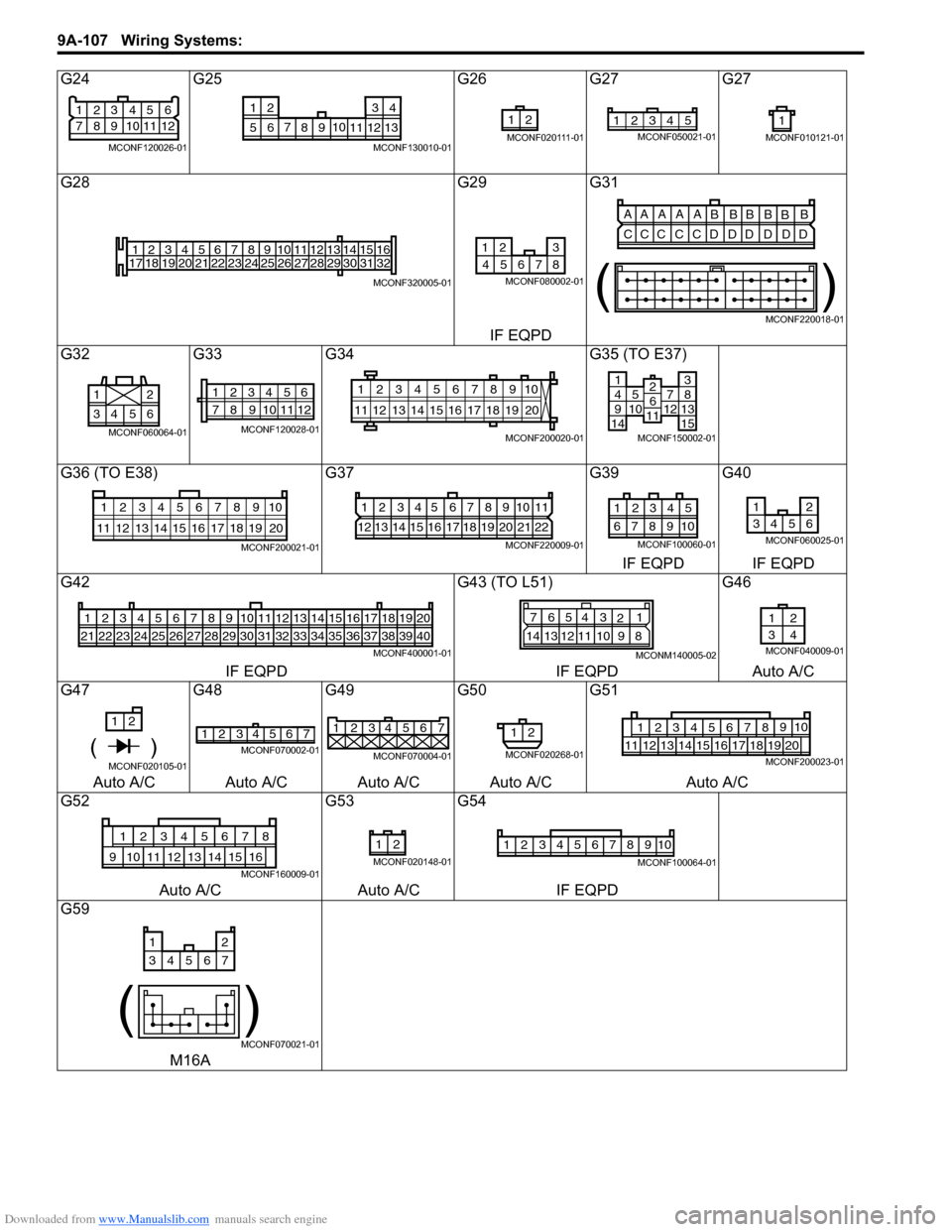
Downloaded from www.Manualslib.com manuals search engine 9A-107 Wiring Systems:
G24G25 G26G27 G27
G28 G29G31
IF EQPD
G32 G33G34 G35 (TO E37)
G36 (TO E38) G37G39G40
IF EQPD IF EQPD
G42 G43 (TO L51)G46
IF EQPD IF EQPDAuto A/C
G47 G48G49G50G51
Auto A/C Auto A/C Auto A/C Auto A/C Auto A/C
G52 G53G54
Auto A/C Auto A/CIF EQPD
G59
M16A
21
83
9 4
10 5
11 6
12
7
MCONF120026-01
710
56 12 34
8 9 11 12 13
MCONF130010-01
21
MCONF020111-01
12345MCONF050021-011
MCONF010121-01
1
17 2
18 3
19 4
20 5
21 6
22 7
23 8
24 9
25 10
26 11
27 12
28 13
29 14
30 15
31 16
32
MCONF320005-01
12 3
8
467 5
MCONF080002-01
AA A A A
BBBB
BB
CCC C CD DD D DD
()
MCONF220018-01
6543 21
MCONF060064-01
12345
78 11 6
12
910
MCONF120028-01
10
11 12 13 14 15 16 17 18 19 123456789
20
MCONF200020-01
14951071214
381315
2611
MCONF150002-01
10
11 12 13 14 15 16 17 18 19 123456789
20
MCONF200021-01
1234567891011
12 13 14 15 16 17 18 19 20 21 22
MCONF220009-01
54321
109876
MCONF100060-01
12
3456
MCONF060025-01
123456
212223242526
7
27
8
28
9
29
10
30
11
31
12
32
13
33
14
34
15
35
16
36
17
37
18
38
19
39
20
40
MCONF400001-01
7 654 3
21
14 13 12 11 10 9 8
MCONM140005-02
12
34
MCONF040009-01
1 2
( )MCONF020105-01
2
14 3657MCONF070002-01
1234567
MCONF070004-01
12
MCONF020268-01
12349105678
11121718192013141516MCONF200023-01
12345678
910151611121314
MCONF160009-01
21
MCONF020148-01
12345678910
MCONF100064-01
12
34567
()
MCONF070021-01
Page 1281 of 1496

Downloaded from www.Manualslib.com manuals search engine Wiring Systems: 9A-110
L27L28 (TO L44) L29
L30 L31 (TO J09) L32 (TO G04) L33 (TO G03) L34
IF EQPD
L35 L36L37 (TO J21) L38 L39L40
IF EQPD
L41 L42 (TO O01) L43 L44 (TO L28) L46 L47
IF EQPD
L48 L51 (TO G43) L53L59 L60
LHD LHD
L61 L62L63L64L65 L66
LHD LHDLHDLHDIF EQPD IF EQPD
L69 L70 (TO M01) L74
IF EQPD
1MCONF010021-01
1 23
456
MCONF060044-0127 28 29 30 31 32 33 34 3536 37 38 39 40 41 42 43 4445 46 47 48 49 50 51
234567 891011 12 13 14 15 16 17 18 1920 21 22 23 24 25 26
1
MCONF510002-01
12
MCONF020212-01
31 32 3433
30
29
24
28
23
27
22
26
21
25
13 2019
14
91011
15
18 16
17 7
1
3
2
4
56 8
12
MCONF340005-01
4321
MCONF040099-01
234
1 5678 910
20191817161514131211
MCONF200003-01
1MCONF010060-01
12
MCONF020210-01
12
MCONF020209-0145678
213
MCONM080013-01
21
MCONM020044-01
1
MCONM010004-011MCONF010060-01
21
MCONF020207-01
45678
213
MCONM080013-01
1
23
456
MCONF060044-01
123
4
65
MCONM060012-01
1
2
MCONF020116-01
1
2
MCONF020013-01
1
2
MCONF020013-01
12567
8
9 1011121314
34
MCONF140012-01
21MCONF020084-01
12
MCONF020266-01
12
MCONF020060-01
12
34
MCONF040143-01
12
34
MCONF040143-01
12
3456
MCONF060025-01
12
3456
MCONF060025-01
21
MCONF020228-01
21
MCONF020228-01
12
3456
MCONF060025-01
2
4 1
3
MCONM040027-01
123 45
678 12 1110
91 3
( )
MCONF130026-01