Compressor SUZUKI SWIFT 2006 2.G Service User Guide
[x] Cancel search | Manufacturer: SUZUKI, Model Year: 2006, Model line: SWIFT, Model: SUZUKI SWIFT 2006 2.GPages: 1496, PDF Size: 34.44 MB
Page 233 of 1496
Downloaded from www.Manualslib.com manuals search engine Engine General Information and Diagnosis: 1A-183
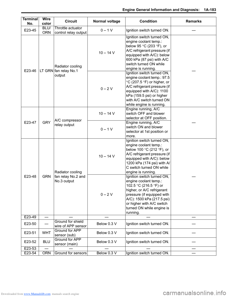
E23-45BLU/
ORNThrottle actuator
control relay output
0 тАУ 1 V Ignition switch turned ON. тАФ
E23-46 LT GRN Radiator cooling
fan relay No.1
output 10 тАУ 14 V
Ignition switch turned ON,
engine coolant temp.:
below 95
┬░C (203 ┬░ F), or
A/C refrigerant pressure (if
equipped with A/C): below
600 kPa (87 psi) with A/C
switch turned ON while
engine is running. тАФ
0 тАУ 2 V Ignition switch turned ON,
engine coolant temp.: 97.5
┬░
C (207.5 ┬░ F) or higher, or
A/C refrigerant pressure (if
equipped with A/C): 1100
kPa (159.5 psi) or higher
with A/C switch turned ON
while engine is running.
E23-47 GRY A/C compressor
relay output 10 тАУ 14 V
Engine running, A/C
switch OFF and blower
selector at OFF position.
тАФ
0 тАУ 1 V Engine running, A/C
switch ON and blower
selector at 1st position or
more.
E23-48 GRN Radiator cooling
fan relay No.2 and
No.3 output 10 тАУ 14 V
Ignition switch turned ON,
engine coolant temp.:
below 100
┬░C (212 ┬░F), or
A/C refrigerant pressure (if
equipped with A/C): below
1200 kPa (174 psi) with A/
C switch turned ON while
engine is running. тАФ
0 тАУ 2 V Ignition switch turned ON,
engine coolant temp.:
102.5
┬░C (216.5 ┬░F) or
higher, or A/C refrigerant
pressure (if equipped with
A/C): 1500 kPa (217.5 psi)
or higher with A/C switch
turned ON while engine is
running.
E23-49 тАФ тАФ тАФ тАФ тАФ
E23-50 тАФ Ground for shield
wire of APP sensor Below 0.3 V Ignition switch turned ON. тАФ
E23-51 WHT Ground for APP
sensor (sub) Below 0.3 V Ignition switch turned ON. тАФ
E23-52 BLU Ground for APP
sensor (main) Below 0.3 V Ignition switch turned ON. тАФ
E23-53 тАФ тАФ тАФ тАФ тАФ
E23-54 ORN Ground for sensors Below 0.3 V Ignition switch turned ON. тАФ
Terminal
No. Wire
color Circuit Normal voltage Condition Remarks
Page 244 of 1496
Downloaded from www.Manualslib.com manuals search engine 1A-194 Engine General Information and Diagnosis:
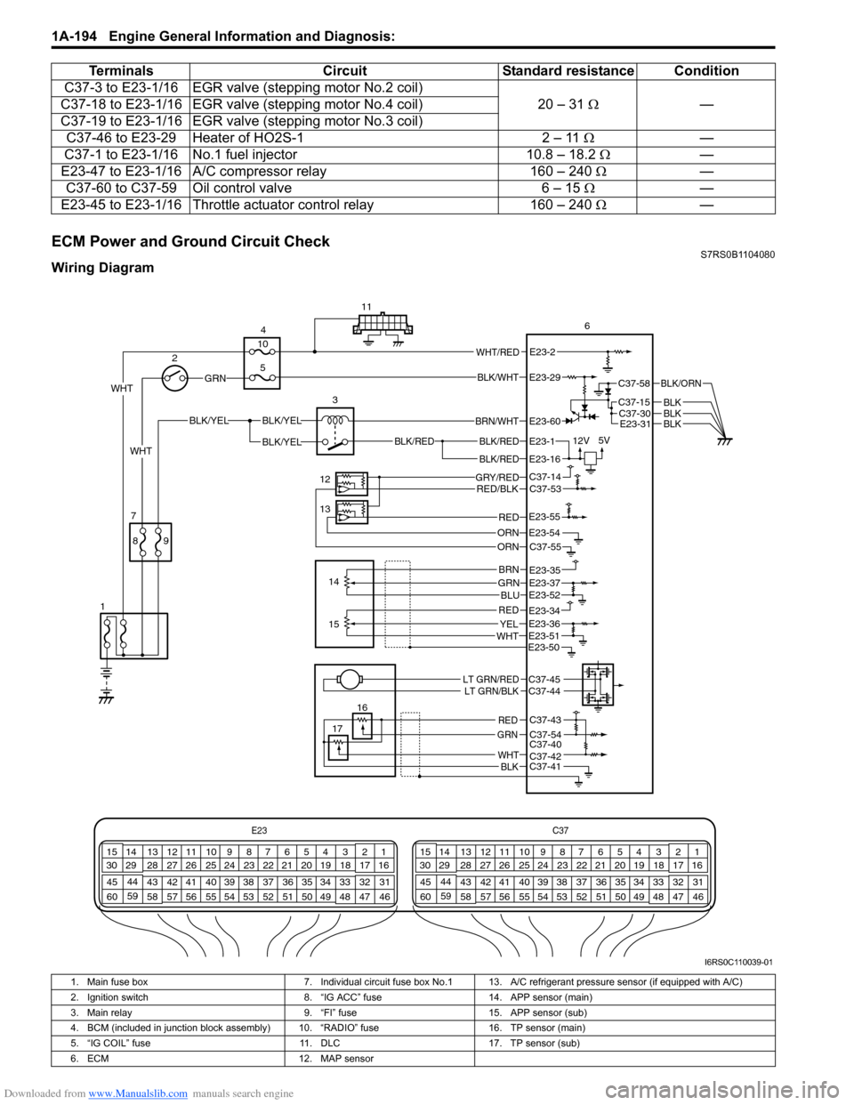
ECM Power and Ground Circuit CheckS7RS0B1104080
Wiring DiagramC37-3 to E23-1/16 EGR valve
(stepping motor No.2 coil)
20 тАУ 31 тДж тАФ
C37-18 to E23-1/16 EGR valv e (stepping motor No.4 coil)
C37-19 to E23-1/16 EGR valv e (stepping motor No.3 coil)
C37-46 to E23-29 Heater of HO2S-1 2 тАУ 11 тДжтАФ
C37-1 to E23-1/16 No.1 fuel injector 10.8 тАУ 18.2 тДж тАФ
E23-47 to E23-1/16 A/C compressor relay 160 тАУ 240 тДж тАФ
C37-60 to C37-59 Oil control valve 6 тАУ 15 тДж тАФ
E23-45 to E23-1/16 Throttle actuator control relay 160 тАУ 240 тДж тАФ
Terminals
CircuitStandard resistance Condition
E23 C37
34
1819
567
1011
17
20
47 46
495051
2122
52 16
25 9
24
14
29
55
57 54 53
59
60 58 2
262728
15
30
56 4832 31
34353637
40
42 39 38
44
45 43 41 331
1213
238
34
1819
567
1011
17
20
47 46
495051
2122
52 16
25 9
24
14
29
55
57 54 53
59
60 58 2
262728
15
30
56 4832 31
34353637
40
42 39 38
44
45 43 41 331
1213
238
BLK/RED
BLK/REDBLK/RED
BLK/YELBLK/YEL
BLK/YEL
GRN
BRN/WHT
12V
5VE23-1
E23-60
E23-16
WHT 2
4
11
6
3
12
13 14
7
1
16
17
89
15
10
5
WHT/REDE23-2
C37-58
C37-15C37-30
BLK/ORN
BLKBLKE23-31BLK
WHT
GRY/REDRED/BLK
ORN
C37-14C37-53
C37-55E23-54
REDE23-55
GRNBRN
BLU
REDYELWHT
E23-35E23-37E23-52
E23-51
E23-34E23-36
E23-50
LT GRN/REDLT GRN/BLKC37-45C37-44
C37-43
C37-54C37-40C37-42C37-41
RED
GRN
WHTBLK
ORN
BLK/WHTE23-29
I6RS0C110039-01
1. Main fuse box 7. Individual circuit fuse box No.1 13. A/C refrigerant pressure sensor (if equipped with A/C)
2. Ignition switch 8. тАЬIG ACCтАЭ fuse14. APP sensor (main)
3. Main relay 9. тАЬFIтАЭ fuse15. APP sensor (sub)
4. BCM (included in junction block assembly) 10. тАЬRADIOтАЭ fuse 16. TP sensor (main)
5. тАЬIG COILтАЭ fuse 11. DLC17. TP sensor (sub)
6. ECM 12. MAP sensor
Page 255 of 1496
Downloaded from www.Manualslib.com manuals search engine Engine General Information and Diagnosis: 1A-205
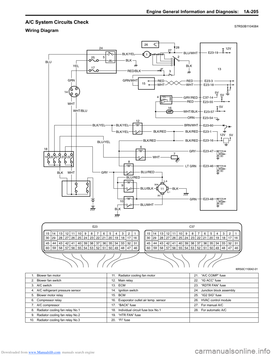
A/C System Circuits CheckS7RS0B1104084
Wiring Diagram
E23C37
34
1819
567
1011
17
20
47 46
495051
2122
52 16
25 9
24
14
29
55
57 54 53
59
60 58 2
262728
15
30
56 4832 31
34353637
40
42 39 38
44
45 43 41 331
1213
238
34
1819
567
1011
17
20
47 46
495051
2122
52 16
25 9
24
14
29
55
57 54 53
59
60 58 2
262728
15
30
56 4832 31
34353637
40
42 39 38
44
45 43 41 331
1213
238
BLK/REDBLK/RED
BLK/YELBLK/YEL
BLK/YEL
BRN/WHT
12V
5V
12
E23-1
E23-60
BLK/RED
LT GRN
BLK/REDE23-16
E23-46
L+
LтАУ
HтАУ
H
+
BLU/RED
BLK
BLUWHTBLK
BLU/BLK
BLU/RED
GRN
GRY
E23-48
8
11
2
3BLU/WHT
REDWHTREDWHTE23-3E23-18
E23-19
6
BLK
WHT
BLK 12V
E23-47 GRY
WHT
YELBLU
WHT
BLK/YEL
RED/BLK
GRN/WHT
WHT/BLU1
713
14
5V
5V
4
E23-55C37-14GRY/REDRED
E23-54ORN 5V
E23-57WHT/BLK16
9
10
25
17
5
24
15
22
BLU/YEL
23212019
GRN
BLK
18
26
28
27
I6RS0C110042-01
1. Blower fan motor 11. Radiator cooling fan motor 21. тАЬA/C COMPтАЭ fuse
2. Blower fan switch 12. Main relay 22. тАЬIG ACCтАЭ fuse
3. A/C switch 13. ECM 23. тАЬRDTR FANтАЭ fuse
4. A/C refrigerant pressure sensor 14. Ignition switch 24. Junction block assembly
5. Blower motor relay 15. BCM 25. тАЬIG2 SIGтАЭ fuse
6. Compressor relay 16. Evaporator outlet air temp. sensor 26. HVAC control module
7. A/C compressor 17. тАЬBACKтАЭ fuse 27. For manual A/C
8. Radiator cooling fan relay No.1 18. Individual circuit fuse box No.1 28. For automatic A/C
9. Radiator cooling fan relay No.2 19. тАЬHTR FANтАЭ fuse
10. Radiator cooling fan relay No.3 20. тАЬFIтАЭ fuse
Page 257 of 1496
Downloaded from www.Manualslib.com manuals search engine Engine General Information and Diagnosis: 1A-207
6A/C evaporator outlet air temp. sensor check
1) Disconnect connectors from ECM with ignition switch
turned OFF.
2) Check for proper connection to тАЬE23-57тАЭ and тАЬE23-54тАЭ wire terminals of ECM connector.
3) If OK, measure resistance between тАЬE23-57тАЭ and тАЬE23- 54тАЭ wire terminals of ECM connector.
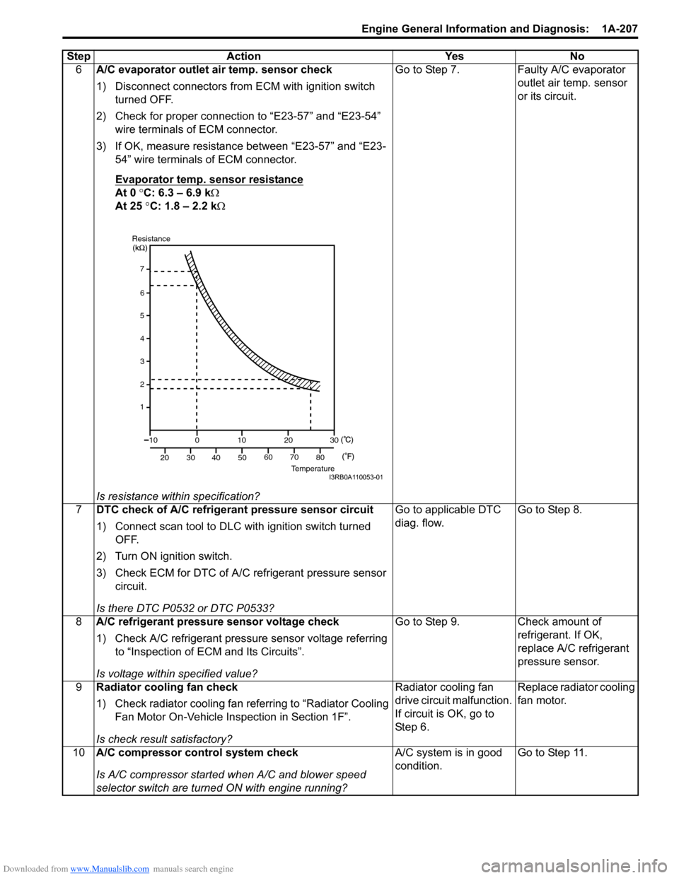
Evaporator temp. sensor resistance
At 0 ┬░C: 6.3 тАУ 6.9 k тДж
At 25 ┬░C: 1.8 тАУ 2.2 k тДж
Is resistance within specification? Go to Step 7. Faulty A/C evaporator
outlet air temp. sensor
or its circuit.
7 DTC check of A/C refrigerant pressure sensor circuit
1) Connect scan tool to DLC with ignition switch turned
OFF.
2) Turn ON ignition switch.
3) Check ECM for DTC of A/C refrigerant pressure sensor circuit.
Is there DTC P0532 or DTC P0533? Go to applicable DTC
diag. flow.
Go to Step 8.
8 A/C refrigerant pressure sensor voltage check
1) Check A/C refrigerant pressure sensor voltage referring
to тАЬInspection of ECM and Its CircuitsтАЭ.
Is voltage within specified value? Go to Step 9. Check amount of
refrigerant. If OK,
replace A/C refrigerant
pressure sensor.
9 Radiator cooling fan check
1) Check radiator cooling fan referring to тАЬRadiator Cooling
Fan Motor On-Vehicle Inspection in Section 1FтАЭ.
Is check result satisfactory? Radiator cooling fan
drive circuit malfunction.
If circuit is OK, go to
St ep 6 .
Replace radiator cooling
fan motor.
10 A/C compressor control system check
Is A/C compressor started when A/C and blower speed
selector switch are turned ON with engine running? A/C system is in good
condition.
Go to Step 11.
Step Action Yes No
7
6
5
4
3
2
1
10
20 30
40 50
0
10
2030
60 70 80
ResistanceTemperatureI3RB0A110053-01
Page 258 of 1496
Downloaded from www.Manualslib.com manuals search engine 1A-208 Engine General Information and Diagnosis:
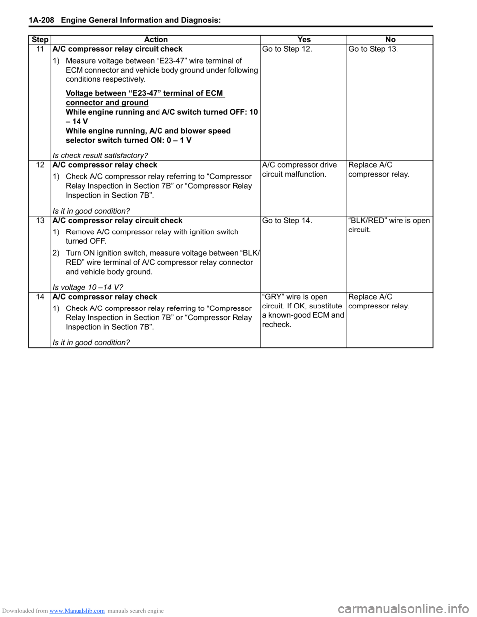
11A/C compressor relay circuit check
1) Measure voltage between тАЬE23-47тАЭ wire terminal of
ECM connector and vehicle body ground under following
conditions respectively.
Voltage between тАЬE23-47тАЭ terminal of ECM
connector and ground
While engine running and A/C switch turned OFF: 10
тАУ 14 V
While engine running, A/C and blower speed
selector switch turned ON: 0 тАУ 1 V
Is check result satisfactory? Go to Step 12. Go to Step 13.
12 A/C compressor relay check
1) Check A/C compressor rela y referring to тАЬCompressor
Relay Inspection in Sectio n 7BтАЭ or тАЬCompressor Relay
Inspection in Section 7BтАЭ.
Is it in good condition? A/C compressor drive
circuit malfunction.
Replace A/C
compressor relay.
13 A/C compressor relay circuit check
1) Remove A/C compressor re lay with ignition switch
turned OFF.
2) Turn ON ignition switch, measure voltage between тАЬBLK/ REDтАЭ wire terminal of A/C compressor relay connector
and vehicle body ground.
Is voltage 10 тАУ14 V? Go to Step 14. тАЬBLK/REDтАЭ wire is open
circuit.
14 A/C compressor relay check
1) Check A/C compressor rela y referring to тАЬCompressor
Relay Inspection in Sectio n 7BтАЭ or тАЬCompressor Relay
Inspection in Section 7BтАЭ.
Is it in good condition? тАЬGRYтАЭ wire is open
circuit. If OK, substitute
a known-good ECM and
recheck.
Replace A/C
compressor relay.
Step Action Yes No
Page 302 of 1496

Downloaded from www.Manualslib.com manuals search engine 1D-17 Engine Mechanical:
Engine Assembly Removal and InstallationS7RS0B1406011
NOTE
After replacing electric throttle body
assembly, perform calibration of throttle
valve referring to тАЬElectric Throttle Body
System Calibration in Section 1CтАЭ.
Removal1) Relieve fuel pressure according to тАЬFuel Pressure Relief Procedure in Section 1GтАЭ.
2) Disconnect negative and pos itive cable at battery.
3) Remove battery and tray.
4) Remove engine hood after disconnecting windshield washer hose.
5) Remove right and left side engine under covers.
6) Remove A/C compressor belt by referring to тАЬCompressor Drive Belt Remo val and Installation in
Section 7BтАЭ or тАЬCompressor Drive Belt Removal and
Installation in Section 7BтАЭ.
7) Drain engine oil, transaxle oil and coolant.
8) Remove cowl top plate referring to тАЬCowl Top Components in Section 9KтАЭ.
9) Remove air cleaner assembly referring to тАЬAir Cleaner ComponentsтАЭ.
10) With hose connected, detach A/C compressor from its bracket (A/C model) referring to тАЬCompressor
Assembly Removal and Installation in Section 7BтАЭ or
тАЬCompressor Assembly Removal and Installation in
Section 7BтАЭ.
CAUTION!
Suspend removed A/C compressor at a place
where no damage will be caused during
removal and installation of engine assembly.
11) Remove intake manifold rear stiffener (1) from intake manifold and cylinder block. 12) Disconnect the following electric wires:
тАв MAP sensor (1)
тАв ECT sensor (2)
тАвEGR valve (3)
тАв CMP sensor (4)
тАв Electric throttle body assembly (5)
тАв Ignition coil assembly (6)
тАв Injectors (7)
тАв Heated oxygen sensor No. 2 (8) and No. 1 (9)
тАв Oil control valve (10)
тАв Engine oil pressure switch (11)
тАв CKP sensor (12)
тАв Knock sensor (13)
тАв Back up light switch (14)
тАв Generator (15)
тАв Starting motor (16)
тАв Ground terminal (17) from intake manifold
тАв Battery ground terminal (18) from exhaust manifold
тАв Battery ground cable (19) from transaxle
тАв Magnet clutch switch of A/C compressor (A/C model)
тАв Each wire harness clamps
тАв Output shaft speed sensor (VSS) (34) (A/T model)
тАв Solenoid valve (33) (A/T model)
тАв Transmission range sensor (32) (A/T model)
тАв Input shaft speed sensor (31) (A/T model)
13) Remove fuse box from its bracket.
14) Disconnect the following cables: тАв Gear select control cable (23) (M/T model)
тАв Gear shift control cable (24) (M/T model)
тАв A/T select cable (A/T model)
15) Disconnect the following hoses: тАв Brake booster hose (26) from intake manifold
тАв Radiator inlet and outlet hoses (20) from each pipe
тАв Heater inlet and outlet hoses (21) from each pipe
тАв Fuel feed hoses (22) from fuel feed pipe
тАв EVAP canister purge valve hose (30) from purge pipe
тАв A/T fluid cooler hoses (A/T model)
16) With hose connected, detach clutch operating cylinder (25). (M/T model)
CAUTION!
Suspend removed clutch operating cylinder
at a place where no damage will be caused
during removal and installation of engine
assembly.
1
I6RS0B141014-01
Page 304 of 1496
Downloaded from www.Manualslib.com manuals search engine 1D-19 Engine Mechanical:
24) Before removing engine with transaxle from engine compartment, recheck to make sure all hoses,
electric wires and cables are disconnected from
engine and transaxle.
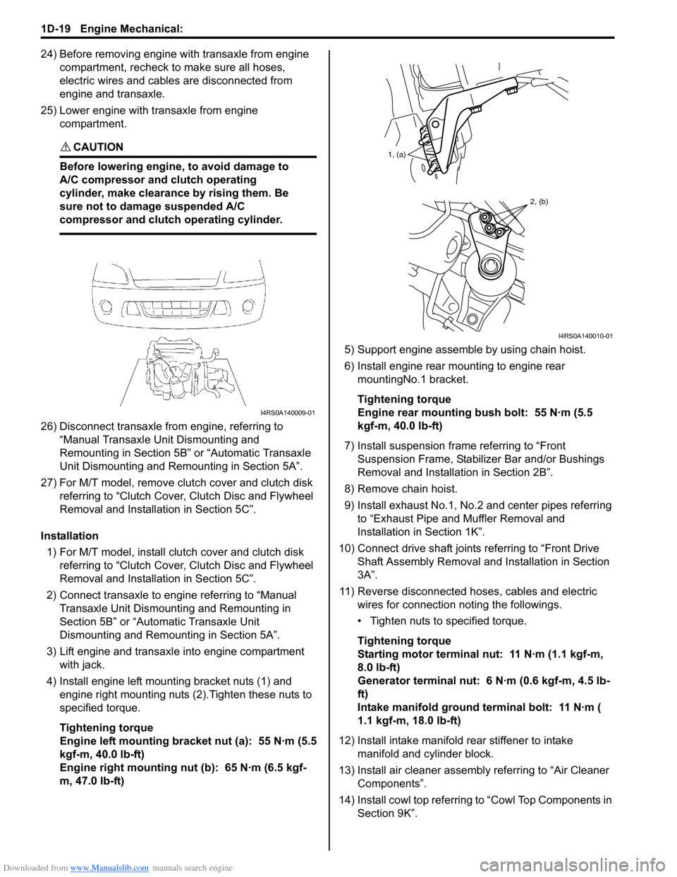
25) Lower engine with transaxle from engine compartment.
CAUTION!
Before lowering engine, to avoid damage to
A/C compressor and clutch operating
cylinder, make clearance by rising them. Be
sure not to damage suspended A/C
compressor and clutch operating cylinder.
26) Disconnect transaxle from engine, referring to тАЬManual Transaxle Unit Dismounting and
Remounting in Section 5BтАЭ or тАЬAutomatic Transaxle
Unit Dismounting and Re mounting in Section 5AтАЭ.
27) For M/T model, remove clutch cover and clutch disk referring to тАЬClutch Cover, Clutch Disc and Flywheel
Removal and Installa tion in Section 5CтАЭ.
Installation 1) For M/T model, install clutch cover and clutch disk referring to тАЬClutch Cover, Clutch Disc and Flywheel
Removal and Installa tion in Section 5CтАЭ.
2) Connect transaxle to engine referring to тАЬManual Transaxle Unit Dismounting and Remounting in
Section 5BтАЭ or тАЬAutomatic Transaxle Unit
Dismounting and Remounting in Section 5AтАЭ.
3) Lift engine and transaxle into engine compartment with jack.
4) Install engine left mounting bracket nuts (1) and engine right mounting nuts (2).Tighten these nuts to
specified torque.
Tightening torque
Engine left mounting bracket nut (a): 55 N┬╖m (5.5
kgf-m, 40.0 lb-ft)
Engine right mounting nut (b): 65 N┬╖m (6.5 kgf-
m, 47.0 lb-ft) 5) Support engine assemble by using chain hoist.
6) Install engine rear mounting to engine rear
mountingNo.1 bracket.
Tightening torque
Engine rear mounting bush bolt: 55 N┬╖m (5.5
kgf-m, 40.0 lb-ft)
7) Install suspension frame referring to тАЬFront Suspension Frame, Stabiliz er Bar and/or Bushings
Removal and Installati on in Section 2BтАЭ.
8) Remove chain hoist.
9) Install exhaust No.1, No.2 and center pipes referring to тАЬExhaust Pipe and Muffler Removal and
Installation in Section 1KтАЭ.
10) Connect drive shaft joints referring to тАЬFront Drive Shaft Assembly Removal and Installation in Section
3AтАЭ.
11) Reverse disconnected hoses, cables and electric wires for connection noting the followings.
тАв Tighten nuts to specified torque.
Tightening torque
Starting motor terminal nut: 11 N┬╖m (1.1 kgf-m,
8.0 lb-ft)
Generator terminal nut: 6 N┬╖m (0.6 kgf-m, 4.5 lb-
ft)
Intake manifold ground terminal bolt: 11 N┬╖m (
1.1 kgf-m, 18.0 lb-ft)
12) Install intake manifold rear stiffener to intake
manifold and cylinder block.
13) Install air cleaner assembly referring to тАЬAir Cleaner ComponentsтАЭ.
14) Install cowl top referring to тАЬCowl Top Components in
Section 9KтАЭ.
I4RS0A140009-01
1, (a)
2, (b)
I4RS0A140010-01
Page 305 of 1496
Downloaded from www.Manualslib.com manuals search engine Engine Mechanical: 1D-20
15) Install A/C compressor to its bracket (if equipped) referring to тАЬCompressor Assembly Removal and
Installation in Section 7BтАЭ or тАЬCompressor Assembly
Removal and Installa tion in Section 7BтАЭ.
16) Adjust A/C compressor belt tension (if equipped) referring to тАЬCompressor Drive Belt Inspection and
Adjustment in Section 7BтАЭ or тАЬCompressor Drive Belt
Inspection and Adjustment in Section 7BтАЭ.
17) Check to ensure that a ll removed parts are back in
place.
Reinstall any necessary parts which have not been
reinstalled.
18) Refill cooling system with coolant referring to тАЬCooling System Flush and Refill in Section 1FтАЭ. 19) Refill engine with engine oil
referring to тАЬEngine Oil
and Filter Change in Section 0BтАЭ.
20) Refill transaxle with transa xle oil referring toтАЬManual
Transaxle Oil Change in Section 5BтАЭ or тАЬA/T Fluid
Change in Section 5AтАЭ.
21) Install battery and tray.
22) Connect positive and negative cable at battery.
23) Install engine hood and connect windshield washer hose.
24) Verify that there is no fu el leakage, coolant leakage,
oil leakage and exhaust gas leakage at each
connection.
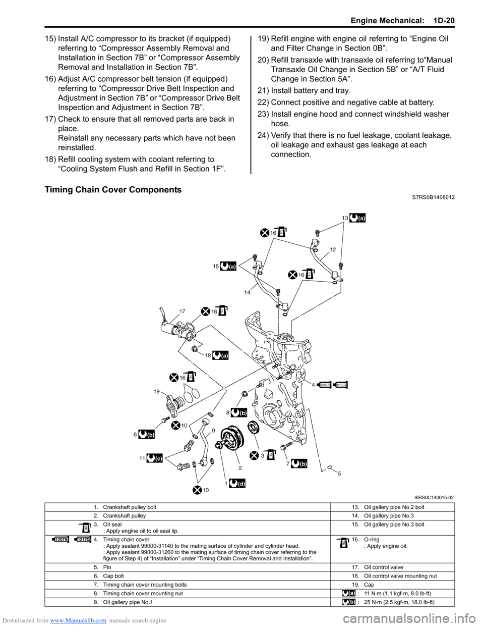
Timing Chain Cover ComponentsS7RS0B1406012
I6RS0C140015-02
1. Crankshaft pulley bolt 13. Oil gallery pipe No.2 bolt
2. Crankshaft pulley 14. Oil gallery pipe No.3
3. Oil seal : Apply engine oil to oil seal lip. 15. Oil gallery pipe No.3 bolt
4. Timing chain cover : Apply sealant 99000-31140 to the mating surface of cylinder and cylinder head.
: Apply sealant 99000-31260 to the mating surface of timing chain cover referring to the
figure of Step 4) of тАЬInstallationтАЭ under тАЬTiming Chain Cover Removal and InstallationтАЭ. 16. O-ring
: Apply engine oil.
5. Pin 17. Oil control valve
6. Cap bolt 18. Oil control valve mounting nut
7. Timing chain cover mounting bolts 19. Cap
8. Timing chain cover mounting nut : 11 N тЛЕm (1.1 kgf-m, 8.0 lb-ft)
9. Oil gallery pipe No.1 :25 NтЛЕm (2.5 kgf-m, 18.0 lb-ft)
Page 330 of 1496
Downloaded from www.Manualslib.com manuals search engine 1D-45 Engine Mechanical:
Pistons, Piston Rings, Connecting Rods and
Cylinders Removal and Installation
S7RS0B1406030
Removal1) Remove engine assembly from vehicle referring to тАЬEngine Assembly Removal and InstallationтАЭ.
2) Remove cylinder head referring to тАЬValves and Cylinder Head Removal and InstallationтАЭ.
3) Mark cylinder number on all pistons, connecting rods
and connecting rod caps using silver pencil or quick
drying paint.
4) Remove rod bearing caps.
5) Decarbonize top of cylinder bore before removing piston from cylinder.
6) Push piston and connecting rod assembly out through the top of cylinder bore.
Installation 1) Apply engine oil to pistons, rings, cylinder walls, connecting rod bearings and crank pins.
NOTE
Do not apply oil between connecting rod and
bearing or between bearing cap and bearing.
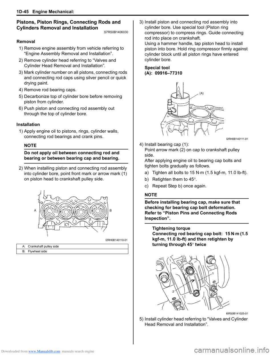
2) When installing piston and connecting rod assembly into cylinder bore, point front mark or arrow mark (1)
on piston head to crankshaft pulley side. 3) Install piston and connecting rod assembly into
cylinder bore. Use special tool (Piston ring
compressor) to compress rings. Guide connecting
rod into place on crankshaft.
Using a hammer handle, tap piston head to install
piston into bore. Hold ring compressor firmly against
cylinder block until all piston rings have entered
cylinder bore.
Special tool
(A): 09916тАУ77310
4) Install bearing cap (1): Point arrow mark (2) on cap to crankshaft pulley
side.
After applying engine oil to bearing cap bolts and
tighten bolts gradually as follows.
a) Tighten all bolts to 15 N тЛЕm (1.5 kgf-m, 11.0 lb-ft).
b) Retighten them to 45 ┬░.
c) Repeat Step b) once again.
NOTE
Before installing bearing cap, make sure that
checking for bearing cap bolt deformation.
Refer to тАЬPiston Pins and Connecting Rods
InspectionтАЭ.
Tightening torque
Connecting rod bearing cap bolt: 15 N тЛЕm (1.5
kgf-m, 11.0 lb-ft) and then retighten by
turning through 45 ┬░ twice
5) Install cylinder head referring to тАЬValves and Cylinder Head Removal and InstallationтАЭ.
A: Crankshaft pulley side
B: Flywheel side
I2RH0B140110-01
I2RH0B140111-01
I6RS0B141025-01
Page 351 of 1496
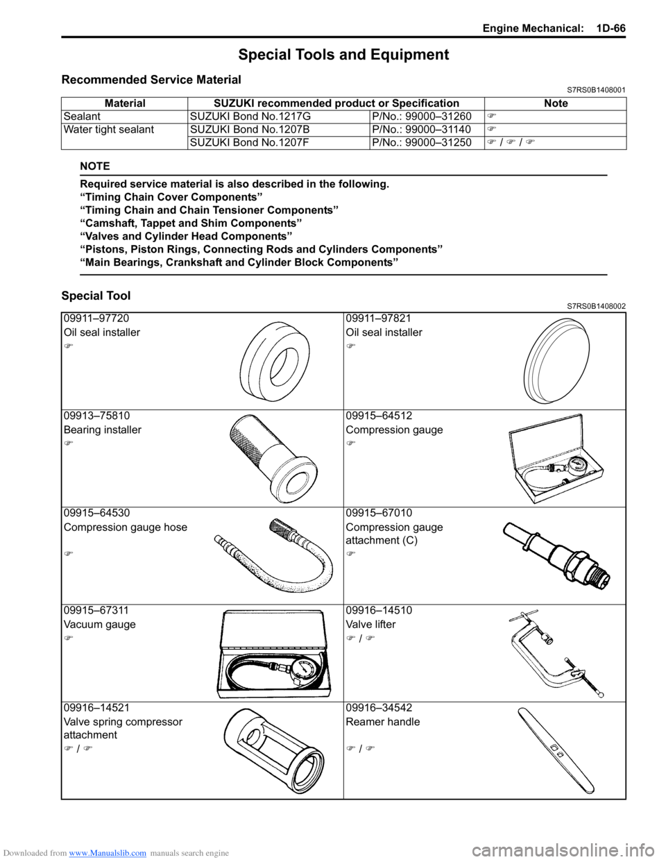
Downloaded from www.Manualslib.com manuals search engine Engine Mechanical: 1D-66
Special Tools and Equipment
Recommended Service MaterialS7RS0B1408001
NOTE
Required service material is also described in the following.
тАЬTiming Chain Cover ComponentsтАЭ
тАЬTiming Chain and Chain Tensioner ComponentsтАЭ
тАЬCamshaft, Tappet and Shim ComponentsтАЭ
тАЬValves and Cylinder Head ComponentsтАЭ
тАЬPistons, Piston Rings, Connecting Rods and Cylinders ComponentsтАЭ
тАЬMain Bearings, Crankshaft and Cylinder Block ComponentsтАЭ
Special ToolS7RS0B1408002
Material SUZUKI recommended product or Specification Note
Sealant SUZUKI Bond No.1217G P/No.: 99000тАУ31260�)
Water tight sealant SUZUKI Bond No.1207B P/No.: 99000тАУ31140�)
SUZUKI Bond No.1207F P/No.: 99000тАУ31250�) / �) / �)
09911тАУ97720 09911тАУ97821
Oil seal installer Oil seal installer
�)�)
09913тАУ75810 09915тАУ64512
Bearing installer Compression gauge
�)�)
09915тАУ64530 09915тАУ67010
Compression gauge hose Compression gauge
attachment (C)
�)�)
09915тАУ67311 09916тАУ14510
Vacuum gauge Valve lifter
�)�) / �)
09916тАУ14521 09916тАУ34542
Valve spring compressor
attachment Reamer handle
�) / �)�) / �)