Coupler SUZUKI SWIFT 2006 2.G Service User Guide
[x] Cancel search | Manufacturer: SUZUKI, Model Year: 2006, Model line: SWIFT, Model: SUZUKI SWIFT 2006 2.GPages: 1496, PDF Size: 34.44 MB
Page 295 of 1496
Downloaded from www.Manualslib.com manuals search engine Engine Mechanical: 1D-10
Air Cleaner Element Inspection and CleaningS7RS0B1406003
Inspection
Check air cleaner element for dirt. Replace excessive
dirty element.
Cleaning
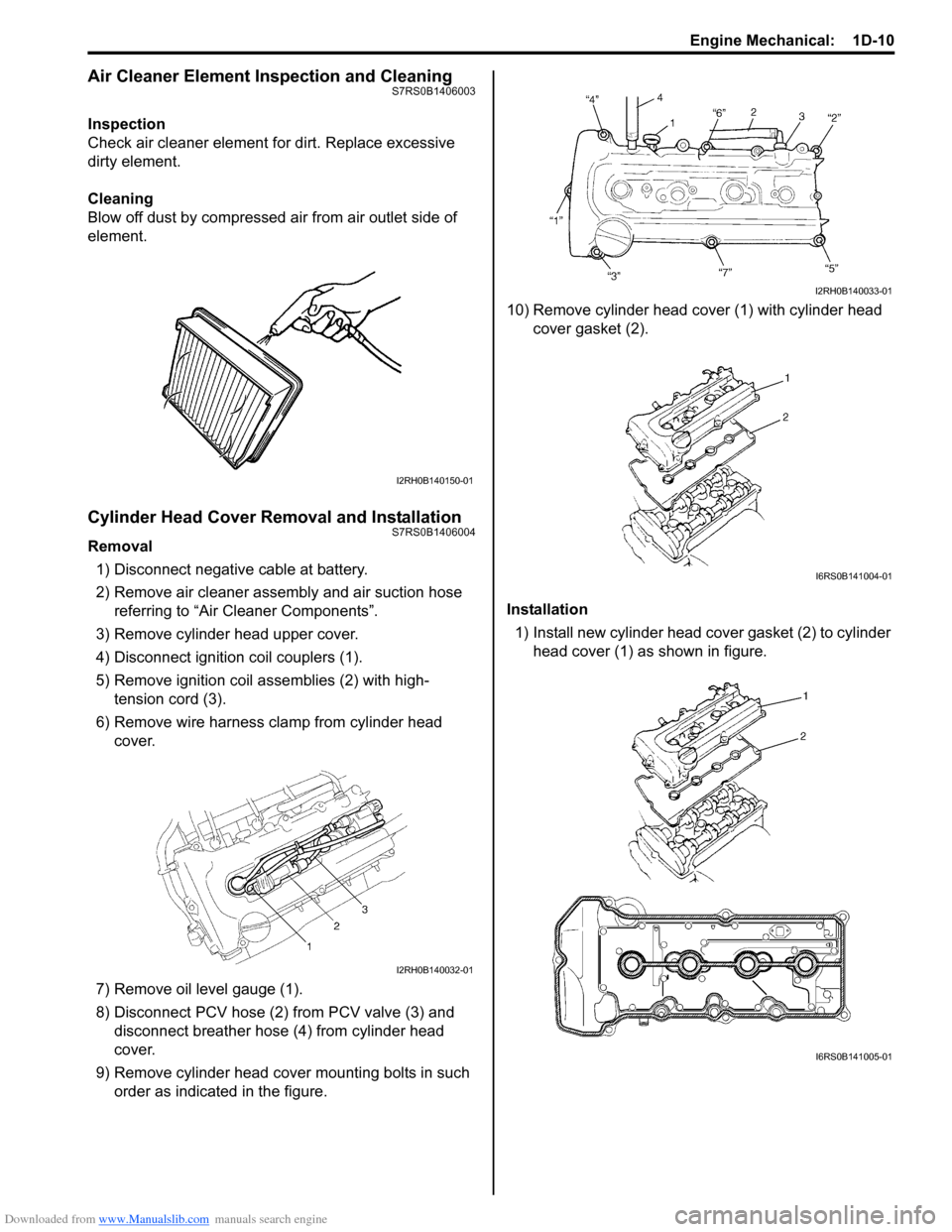
Blow off dust by compressed air from air outlet side of
element.
Cylinder Head Cover Removal and InstallationS7RS0B1406004
Removal1) Disconnect negative cable at battery.
2) Remove air cleaner assembly and air suction hose referring to “Air Cleaner Components”.
3) Remove cylinder head upper cover.
4) Disconnect ignition coil couplers (1).
5) Remove ignition coil assemblies (2) with high- tension cord (3).
6) Remove wire harness clamp from cylinder head cover.
7) Remove oil level gauge (1).
8) Disconnect PCV hose (2) from PCV valve (3) and disconnect breather hose (4) from cylinder head
cover.
9) Remove cylinder head cove r mounting bolts in such
order as indicated in the figure. 10) Remove cylinder head cover (1) with cylinder head
cover gasket (2).
Installation 1) Install new cylinder head cover gasket (2) to cylinder
head cover (1) as shown in figure.
I2RH0B140150-01
I2RH0B140032-01
I2RH0B140033-01
I6RS0B141004-01
I6RS0B141005-01
Page 296 of 1496
Downloaded from www.Manualslib.com manuals search engine 1D-11 Engine Mechanical:
2) Remove oil, old sealant, and dust from sealing surfaces on cylinder head and cover. After cleaning,
apply sealant “A” to the following point.
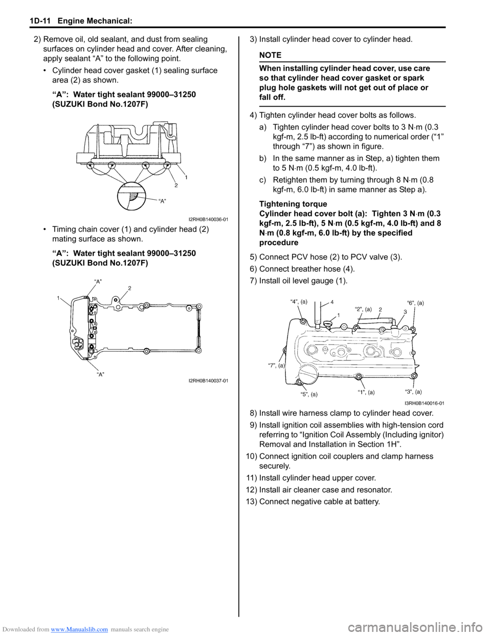
• Cylinder head cover gasket (1) sealing surface area (2) as shown.
“A”: Water tight sealant 99000–31250
(SUZUKI Bond No.1207F)
• Timing chain cover (1) and cylinder head (2) mating surface as shown.
“A”: Water tight sealant 99000–31250
(SUZUKI Bond No.1207F) 3) Install cylinder head cover to cylinder head.
NOTE
When installing cylinder head cover, use care
so that cylinder head cover gasket or spark
plug hole gaskets will not get out of place or
fall off.
4) Tighten cylinder head cover bolts as follows.
a) Tighten cylinder head cover bolts to 3 N ⋅m (0.3
kgf-m, 2.5 lb-ft) according to numerical order (“1”
through “7”) as shown in figure.
b) In the same manner as in Step, a) tighten them
to 5 N ⋅m (0.5 kgf-m, 4.0 lb-ft).
c) Retighten them by turning through 8 N ⋅m (0.8
kgf-m, 6.0 lb-ft) in same manner as Step a).
Tightening torque
Cylinder head cover bolt (a): Tighten 3 N ⋅m (0.3
kgf-m, 2.5 lb-ft), 5 N ⋅m (0.5 kgf-m, 4.0 lb-ft) and 8
N ⋅m (0.8 kgf-m, 6.0 lb-ft) by the specified
procedure
5) Connect PCV hose (2) to PCV valve (3).
6) Connect breather hose (4).
7) Install oil level gauge (1).
8) Install wire harness clamp to cylinder head cover.
9) Install ignition coil assemb lies with high-tension cord
referring to “Ignit ion Coil Assembly (Including ignitor)
Removal and Installati on in Section 1H”.
10) Connect ignition coil couplers and clamp harness securely.
11) Install cylinder head upper cover.
12) Install air cleaner case and resonator.
13) Connect negative cable at battery.
I2RH0B140036-01
I2RH0B140037-01
I3RH0B140016-01
Page 299 of 1496
Downloaded from www.Manualslib.com manuals search engine Engine Mechanical: 1D-14
Throttle Body CleaningS7RS0B1406008
Clean electric throttle body assembly referring to
“Throttle Valve Visual Check” under “Electric Throttle
Body Assembly On-Vehicle Inspection in Section 1C”.
Intake Manifold Removal and InstallationS7RS0B1406009
Removal1) Remove cowl top plate referring to “Cowl Top Components in Section 9K”.
2) Remove throttle body referring to “Electric Throttle Body Assembly Removal and Installation”.
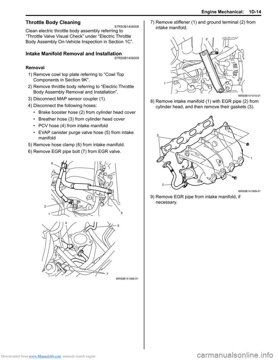
3) Disconnect MAP sensor coupler (1).
4) Disconnect the following hoses: • Brake booster hose (2) from cylinder head cover
• Breather hose (3) from cylinder head cover
• PCV hose (4) from intake manifold
• EVAP canister purge valve hose (5) from intake manifold
5) Remove hose clamp (6) from intake manifold.
6) Remove EGR pipe bolt (7) from EGR valve. 7) Remove stiffener (1) and ground terminal (2) from
intake manifold.
8) Remove intake manifold (1) with EGR pipe (2) from
cylinder head, and then remove their gaskets (3).
9) Remove EGR pipe from intake manifold, if necessary.
6
2 1
3
54
7I6RS0B141008-01
1
2
I6RS0B141010-01
3
2
1
I6RS0B141009-01
Page 354 of 1496
Downloaded from www.Manualslib.com manuals search engine 1E-2 Engine Lubrication System:
Diagnostic Information and Procedures
Oil Pressure CheckS7RS0B1504001
WARNING!
To avoid danger of being burned, do not
touch exhaust system when it is still hot.
NOTE
Prior to checking oil pressure, check the
following.
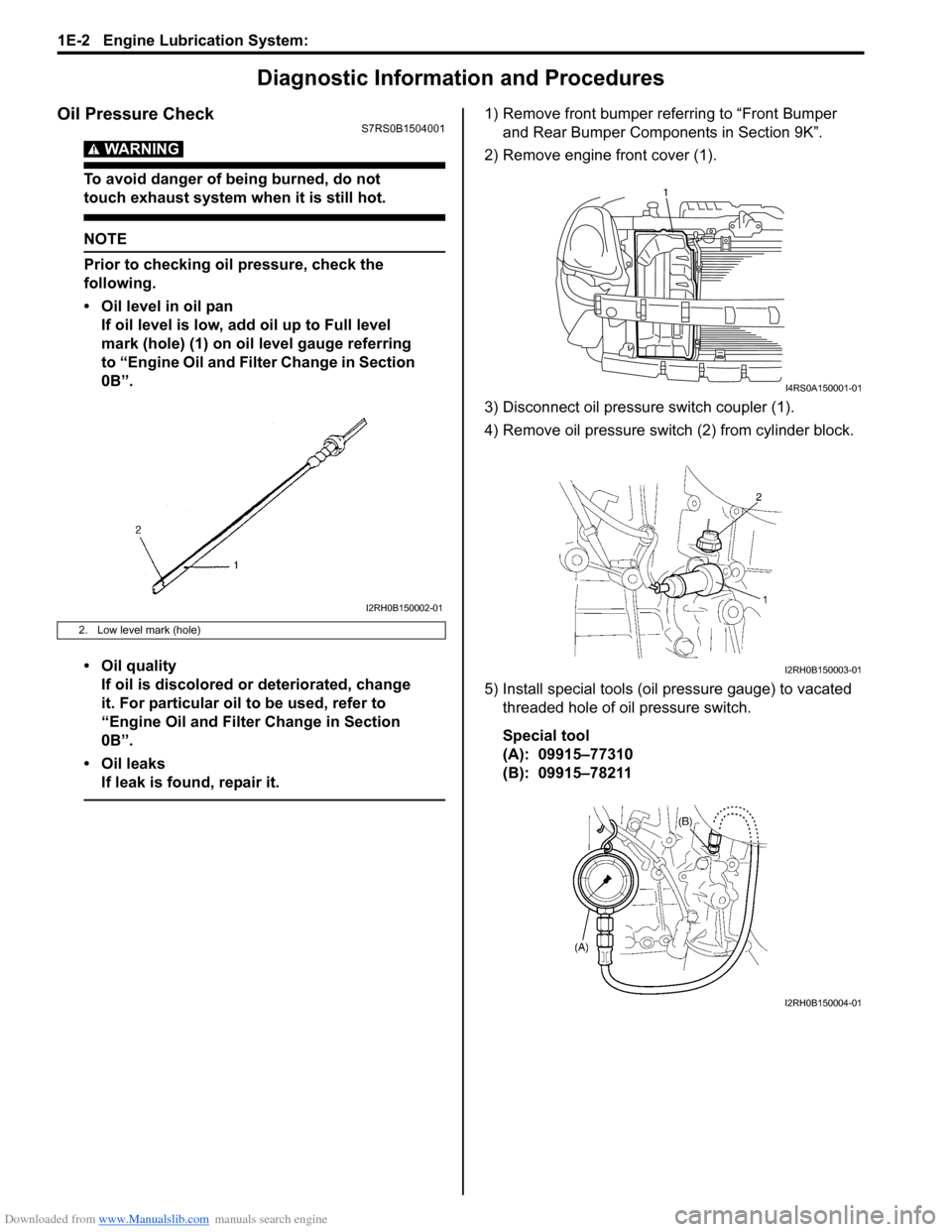
• Oil level in oil pan
If oil level is low, add oil up to Full level
mark (hole) (1) on oil level gauge referring
to “Engine Oil and Filter Change in Section
0B”.
• Oil quality If oil is discolored or deteriorated, change
it. For particular oil to be used, refer to
“Engine Oil and Filter Change in Section
0B”.
• Oil leaks If leak is found, repair it.
1) Remove front bumper referring to “Front Bumper and Rear Bumper Components in Section 9K”.
2) Remove engine front cover (1).
3) Disconnect oil pressure switch coupler (1).
4) Remove oil pressure swit ch (2) from cylinder block.
5) Install special tools (oil pressure gauge) to vacated threaded hole of oil pressure switch.
Special tool
(A): 09915–77310
(B): 09915–78211
2. Low level mark (hole)
I2RH0B150002-01
1
I4RS0A150001-01
I2RH0B150003-01
I2RH0B150004-01
Page 355 of 1496
Downloaded from www.Manualslib.com manuals search engine Engine Lubrication System: 1E-3
6) Start engine and warm engine up to normal operating temperature.
NOTE
Be sure to shift transaxle gear shift lever in
“Neutral” (shift select lever in “P” range for
A/T vehicle), set parking brake and block
drive wheels.
7) After warming up, raise engine speed to 4,000 r/min. and measure oil pressure.
Oil pressure specification
More than 270 kPa (2.7 kg/cm2, 39.8 psi) at 4,000
r/min. (rpm)
8) After checking oil pressure, stop engine and remove oil pressure gauge and attachment.
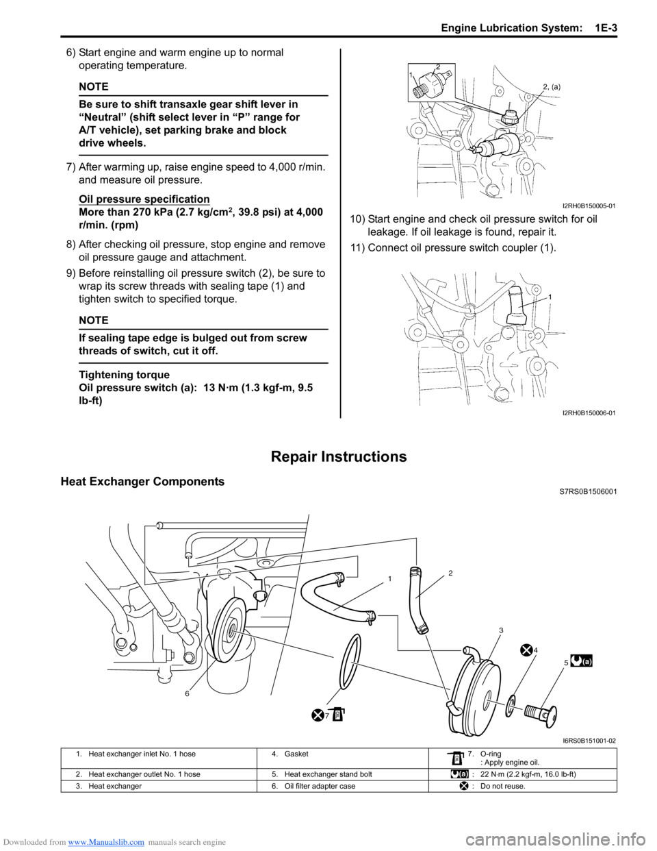
9) Before reinstalling oil pressure switch (2), be sure to
wrap its screw threads with sealing tape (1) and
tighten switch to specified torque.
NOTE
If sealing tape edge is bulged out from screw
threads of switch, cut it off.
Tightening torque
Oil pressure switch (a): 13 N·m (1.3 kgf-m, 9.5
lb-ft) 10) Start engine and check oil pressure switch for oil
leakage. If oil leakage is found, repair it.
11) Connect oil pressure switch coupler (1).
Repair Instructions
Heat Exchanger ComponentsS7RS0B1506001
I2RH0B150005-01
I2RH0B150006-01
3
4
5
7
6
(a)
2
1
I6RS0B151001-02
1. Heat exchanger inlet No. 1 hose 4. Gasket7. O-ring
: Apply engine oil.
2. Heat exchanger outlet No. 1 hose 5. Heat exchanger stand bolt : 22 N⋅m (2.2 kgf-m, 16.0 lb-ft)
3. Heat exchanger 6. Oil filter adapter case : Do not reuse.
Page 372 of 1496
Downloaded from www.Manualslib.com manuals search engine 1F-9 Engine Cooling System:
Radiator Cooling Fan Motor On-Vehicle
Inspection
S7RS0B1606009
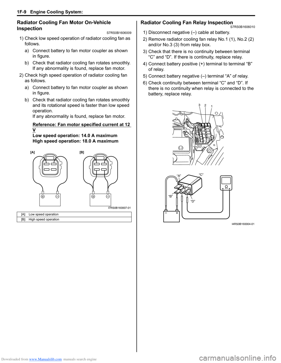
1) Check low speed operation of radiator cooling fan as follows.
a) Connect battery to fan motor coupler as shown in figure.
b) Check that radiator cooling fan rotates smoothly. If any abnormality is found, replace fan motor.
2) Check high speed operation of radiator cooling fan as follows.
a) Connect battery to fan motor coupler as shown in figure.
b) Check that radiator cooling fan rotates smoothly and its rotational speed is faster than low speed
operation.
If any abnormality is found, replace fan motor.
Reference: Fan motor sp ecified current at 12
V
Low speed operation: 14.0 A maximum
High speed operation: 18.0 A maximum
Radiator Cooling Fan Relay InspectionS7RS0B1606010
1) Disconnect negative (–) cable at battery.
2) Remove radiator cooling fa n relay No.1 (1), No.2 (2)
and/or No.3 (3) from relay box.
3) Check that there is no continuity between terminal “C” and “D”. If there is continuity, replace relay.
4) Connect battery positive (+ ) terminal to terminal “B”
of relay.
5) Connect battery negative (–) terminal “A” of relay.
6) Check continuity between terminal “C” and “D”. If there is no continuity when relay is connected to the
battery, replace relay.
[A]: Low speed operation
[B]: High speed operation
[A] [B]
I7RS0B160007-01
“D”
“B” “A”
“C”
1
2
3
I4RS0B160004-01
Page 383 of 1496
Downloaded from www.Manualslib.com manuals search engine Fuel System: 1G-8
Installation1) Install clamps to marked location on pipes. If clamp is deformed, its claw is bent or broken, replace it with
new one.
2) Install pipes with pipe clamps to vehicle.
3) Connect fuel hoses and pipes to each pipe referring to “Fuel Hose Disconnecting and Reconnecting”.
4) Connect negative cable at battery.
5) With engine OFF, turn igniti on switch to ON position
and check for fuel leaks.
Fuel Injector On-Vehicle InspectionS7RS0B1706007
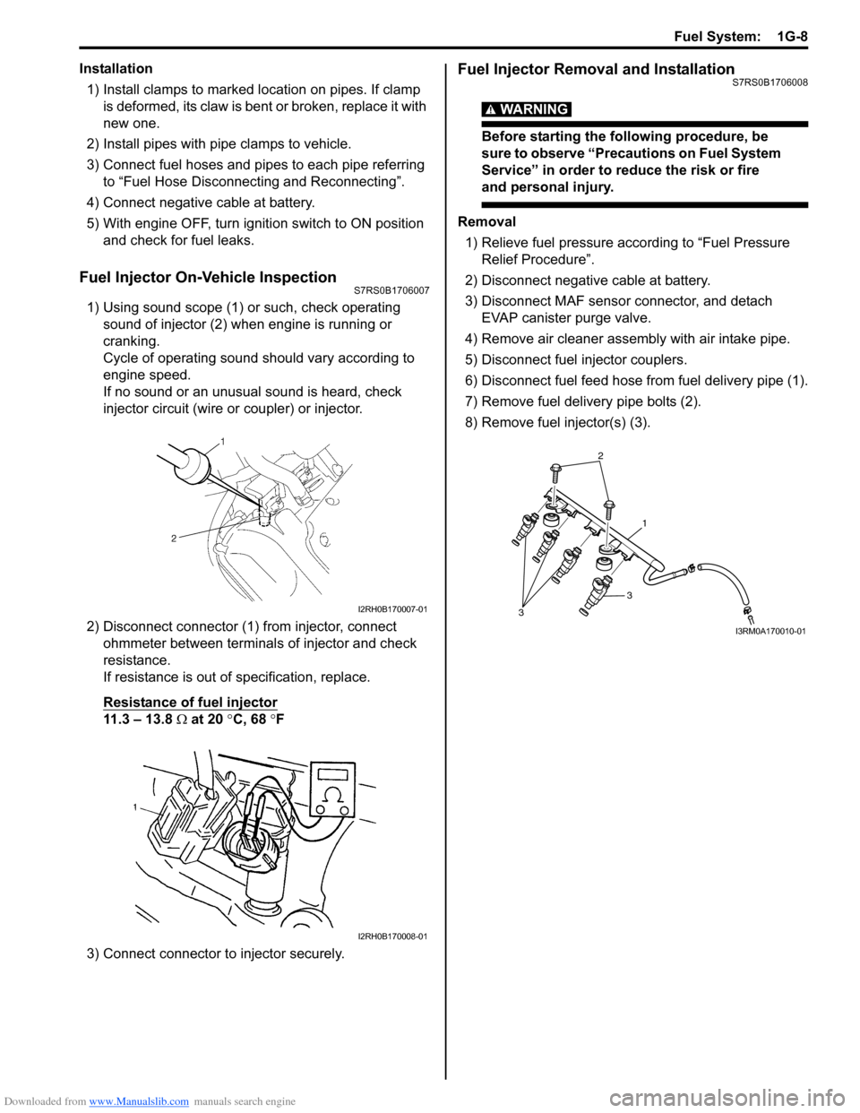
1) Using sound scope (1) or such, check operating sound of injector (2) when engine is running or
cranking.
Cycle of operating sound should vary according to
engine speed.
If no sound or an unusual sound is heard, check
injector circuit (wire or coupler) or injector.
2) Disconnect connector (1) from injector, connect ohmmeter between terminals of injector and check
resistance.
If resistance is out of specification, replace.
Resistance of fuel injector
11.3 – 13.8 Ω at 20 °C, 68 °F
3) Connect connector to injector securely.
Fuel Injector Removal and InstallationS7RS0B1706008
WARNING!
Before starting the following procedure, be
sure to observe “Precautions on Fuel System
Service” in order to reduce the risk or fire
and personal injury.
Removal 1) Relieve fuel pressure according to “Fuel Pressure Relief Procedure”.
2) Disconnect negative cable at battery.
3) Disconnect MAF sensor connector, and detach EVAP canister purge valve.
4) Remove air cleaner assembly with air intake pipe.
5) Disconnect fuel injector couplers.
6) Disconnect fuel feed hose from fuel delivery pipe (1).
7) Remove fuel delivery pipe bolts (2).
8) Remove fuel injector(s) (3).
I2RH0B170007-01
I2RH0B170008-01
2
1
3
3
I3RM0A170010-01
Page 398 of 1496
Downloaded from www.Manualslib.com manuals search engine 1H-6 Ignition System:
Ignition Spark TestS7RS0B1804004
1) Remove air cleaner assembly with air intake pipe.
2) Disconnect all injector couplers from injectors.
WARNING!
Without disconnection of injector couplers,
combustible gas may come out from spark
plug holes during this test and may get
ignited in engine room.
3) Remove spark plug and check it for condition and
type referring to “Spark Plug Inspection”.
4) If OK, connect ignition coil coupler to ignition coil assembly and connect spark plug to ignition coil
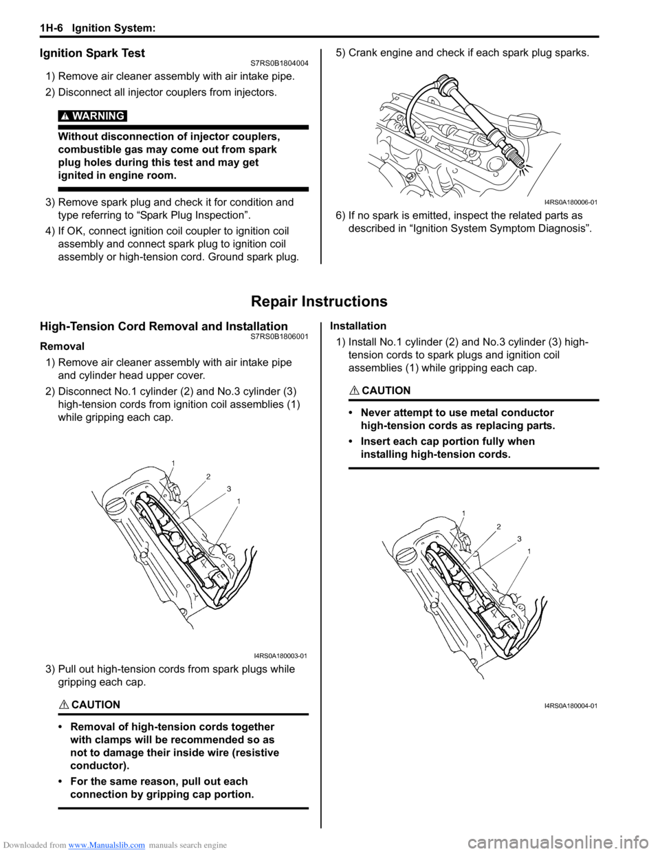
assembly or high-tension cord. Ground spark plug. 5) Crank engine and check if each spark plug sparks.
6) If no spark is emitted, inspect the related parts as
described in “Ignition System Symptom Diagnosis”.
Repair Instructions
High-Tension Cord Removal and InstallationS7RS0B1806001
Removal
1) Remove air cleaner assembly with air intake pipe and cylinder head upper cover.
2) Disconnect No.1 cylinder (2) and No.3 cylinder (3)
high-tension cords from ignition coil assemblies (1)
while gripping each cap.
3) Pull out high-tension cords from spark plugs while gripping each cap.
CAUTION!
• Removal of high-tension cords together with clamps will be recommended so as
not to damage their inside wire (resistive
conductor).
• For the same reason, pull out each connection by gripping cap portion.
Installation
1) Install No.1 cylinder (2) and No.3 cylinder (3) high-
tension cords to spark plugs and ignition coil
assemblies (1) while gripping each cap.
CAUTION!
• Never attempt to use metal conductor high-tension cords as replacing parts.
• Insert each cap portion fully when installing high-tension cords.
I4RS0A180006-01
I4RS0A180003-01
I4RS0A180004-01
Page 400 of 1496

Downloaded from www.Manualslib.com manuals search engine 1H-8 Ignition System:
Ignition Coil Assembly (Including ignitor)
Removal and Installation
S7RS0B1806005
Removal1) Disconnect negative (–) cable at battery.
2) Remove air cleaner assembly with air intake pipe and cylinder head upper cover.
3) Disconnect ignition coil coupler.
4) Disconnect high-tension cord (3) from ignition coil assembly (2).
5) Remove ignition coil bolts (1) and then pull out ignition coil assembly.
Installation 1) Install ignition coil assembly (2).
2) Tighten ignition coil bolts (1) to specified torque, and then connect igni tion coil coupler.
Tightening torque
Ignition coil bolt (a): 10 N·m (1.0 kgf-m, 7.5 lb-ft)
3) Install high-tension cord (3) to ignition coil assembly while gripping its cap.
4) Install cylinder head upper cover and air cleaner assembly with air intake pipe.
5) Connect negative (–) cable to battery.
Ignition Coil Assembly (Including ignitor)
Inspection
S7RS0B1806006
Measure secondary coil for resistance.
If resistance is out of specification, replace ignition coil
assembly.
Secondary coil resistance
7.5 – 10.3 k Ω at 20 °C, 68 ° F
Ignition Timing InspectionS7RS0B1806007
NOTE
• Ignition timing is not adjustable. If ignition
timing is out of specification, check
system related parts.
• Before starting engine, place transmission gear shift lever in “Neutral” (shift selector
lever to “P” range for A/T model), and set
parking brake.
1) Connect scan tool to DLC (1) with ignition switch OFF.
Special tool
(A): SUZUKI scan tool
2) Start engine and warm it up to normal operating temperature.
3) Make sure that all of electrical loads except ignition are switched off.
4) Check to be sure that idle speed is within specification referring to “Idle Speed and IAC
Throttle Valve Opening Inspection in Section 1A”
5) Fix ignition timing by using “Fixed Spark” of “Misc Test” mode on scan tool.
I2RH0B180006-01
I3RM0A180004-01
I2RH0B180007-01
(A)
1
I4RS0B180003-01
Page 403 of 1496
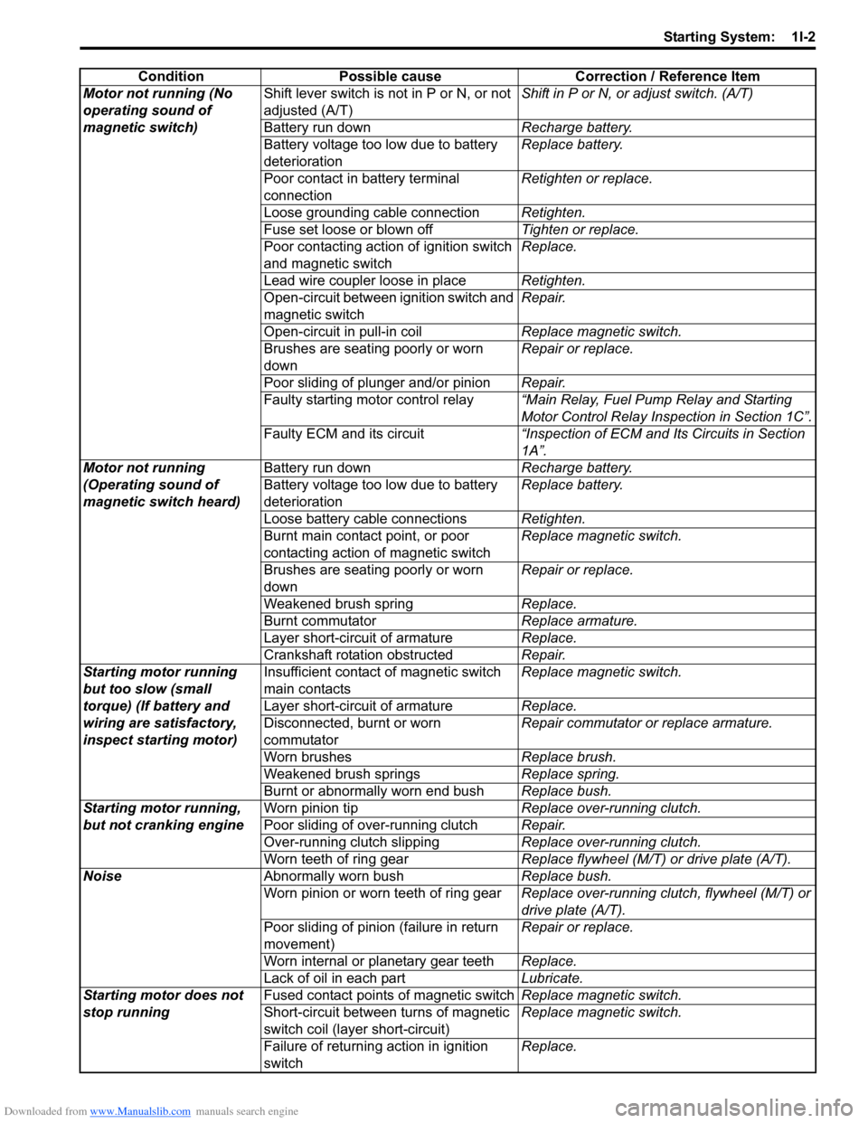
Downloaded from www.Manualslib.com manuals search engine Starting System: 1I-2
ConditionPossible cause Correction / Reference Item
Motor not running (No
operating sound of
magnetic switch) Shift lever switch is not in P or N, or not
adjusted (A/T)
Shift in P or N, or
adjust switch. (A/T)
Battery run down Recharge battery.
Battery voltage too low due to battery
deterioration Replace battery.
Poor contact in battery terminal
connection Retighten or replace.
Loose grounding cable connection Retighten.
Fuse set loose or blown off Tighten or replace.
Poor contacting action of ignition switch
and magnetic switch Replace.
Lead wire coupler loose in place Retighten.
Open-circuit between ignition switch and
magnetic switch Repair.
Open-circuit in pull-in coil Replace magnetic switch.
Brushes are seating poorly or worn
down Repair or replace.
Poor sliding of plunger and/or pinion Repair.
Faulty starting motor control relay “Main Relay, Fuel Pump Relay and Starting
Motor Control Relay Inspection in Section 1C”.
Faulty ECM and its circuit “Inspection of ECM and Its Circuits in Section
1A”.
Motor not running
(Operating sound of
magnetic switch heard) Battery run down
Recharge battery.
Battery voltage too low due to battery
deterioration Replace battery.
Loose battery cable connections Retighten.
Burnt main contact point, or poor
contacting action of magnetic switch Replace magnetic switch.
Brushes are seating poorly or worn
down Repair or replace.
Weakened brush spring Replace.
Burnt commutator Replace armature.
Layer short-circuit of armature Replace.
Crankshaft rotation obstructed Repair.
Starting motor running
but too slow (small
torque) (If battery and
wiring are satisfactory,
inspect starting motor) Insufficient contact
of magnetic switch
main contacts Replace magnetic switch.
Layer short-circuit of armature Replace.
Disconnected, burnt or worn
commutator Repair commutator or replace armature.
Worn brushes Replace brush.
Weakened brush springs Replace spring.
Burnt or abnormally worn end bush Replace bush.
Starting motor running,
but not cranking engine Worn pinion tip
Replace over-running clutch.
Poor sliding of over-running clutch Repair.
Over-running clutch slipping Replace over-running clutch.
Worn teeth of ring gear Replace flywheel (M/T) or drive plate (A/T).
Noise Abnormally worn bush Replace bush.
Worn pinion or worn teeth of ring gear Replace over-running clutch, flywheel (M/T) or
drive plate (A/T).
Poor sliding of pinion (failure in return
movement) Repair or replace.
Worn internal or planetary gear teeth Replace.
Lack of oil in each part Lubricate.
Starting motor does not
stop running Fused contact points of magnetic switch
Replace magnetic switch.
Short-circuit between turns of magnetic
switch coil (layer short-circuit) Replace magnetic switch.
Failure of returning action in ignition
switch Replace.