Engine vacuum check SUZUKI SWIFT 2006 2.G Service User Guide
[x] Cancel search | Manufacturer: SUZUKI, Model Year: 2006, Model line: SWIFT, Model: SUZUKI SWIFT 2006 2.GPages: 1496, PDF Size: 34.44 MB
Page 271 of 1496
Downloaded from www.Manualslib.com manuals search engine Aux. Emission Control Devices: 1B-4
EVAP Canister InspectionS7RS0B1206006
WARNING!
DO NOT SUCK nozzles on EVAP canister.
Fuel vapor inside EVAP canister is harmful.
1) Check outside of EVAP canister visually.
2) Disconnect vacuum hoses from EVAP canister.
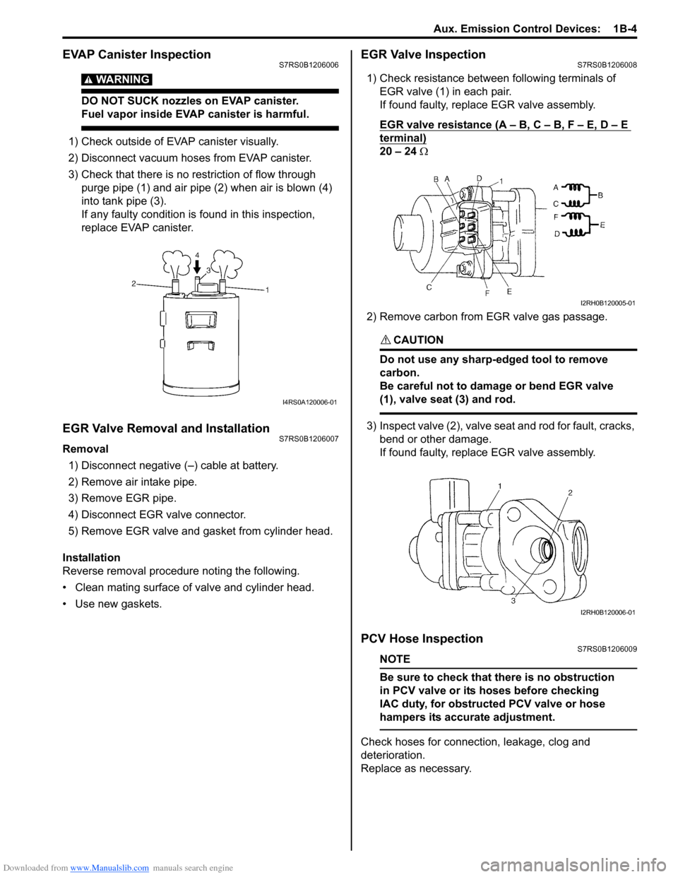
3) Check that there is no restriction of flow through purge pipe (1) and air pipe (2) when air is blown (4)
into tank pipe (3).
If any faulty condition is found in this inspection,
replace EVAP canister.
EGR Valve Removal and InstallationS7RS0B1206007
Removal
1) Disconnect negative (–) cable at battery.
2) Remove air intake pipe.
3) Remove EGR pipe.
4) Disconnect EGR valve connector.
5) Remove EGR valve and gasket from cylinder head.
Installation
Reverse removal procedure noting the following.
• Clean mating surface of valve and cylinder head.
• Use new gaskets.
EGR Valve InspectionS7RS0B1206008
1) Check resistance between following terminals of EGR valve (1) in each pair.
If found faulty, replace EGR valve assembly.
EGR valve resistance (A – B, C – B, F – E, D – E
terminal)
20 – 24 Ω
2) Remove carbon from EGR valve gas passage.
CAUTION!
Do not use any sharp-edged tool to remove
carbon.
Be careful not to damage or bend EGR valve
(1), valve seat (3) and rod.
3) Inspect valve (2), valve seat and rod for fault, cracks, bend or other damage.
If found faulty, replace EGR valve assembly.
PCV Hose InspectionS7RS0B1206009
NOTE
Be sure to check that there is no obstruction
in PCV valve or its hoses before checking
IAC duty, for obstructed PCV valve or hose
hampers its accurate adjustment.
Check hoses for connection, leakage, clog and
deterioration.
Replace as necessary.
I4RS0A120006-01
I2RH0B120005-01
I2RH0B120006-01
Page 272 of 1496
Downloaded from www.Manualslib.com manuals search engine 1B-5 Aux. Emission Control Devices:
PCV Valve InspectionS7RS0B1206010
NOTE
Be sure to check that there is no obstruction
in PCV valve or its hoses before checking
IAC duty, for obstructed PCV valve or hose
hampers its accurate adjustment.
1) Detach air cleaner assembly.
2) Disconnect PCV valve from cylinder head cover and install plug to head cover hole.
3) Install air cleaner assembly temporarily.
4) Run engine at idle.
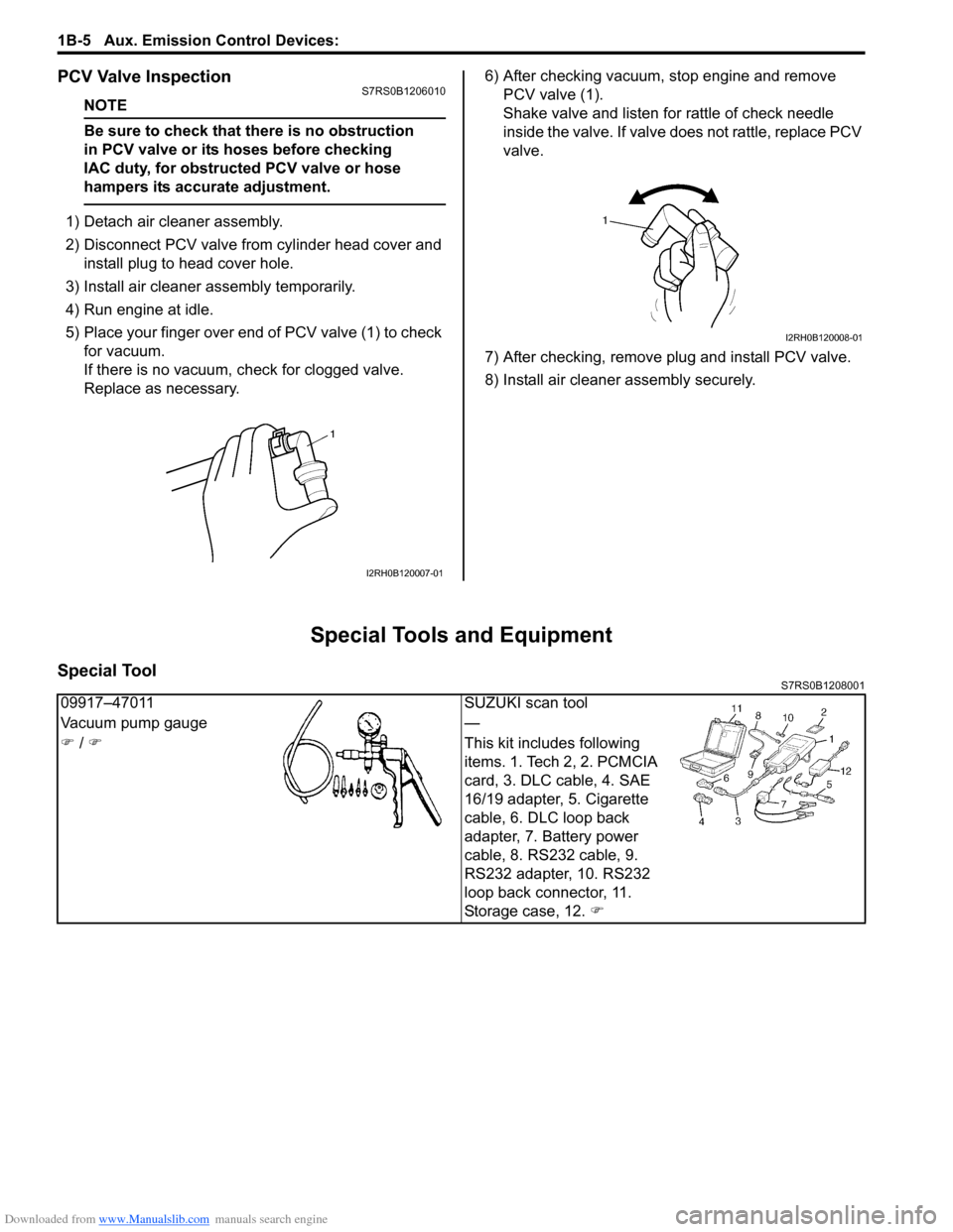
5) Place your finger over end of PCV valve (1) to check for vacuum.
If there is no vacuum, ch eck for clogged valve.
Replace as necessary. 6) After checking vacuum, stop engine and remove
PCV valve (1).
Shake valve and listen for rattle of check needle
inside the valve. If valve does not rattle, replace PCV
valve.
7) After checking, remove plug and install PCV valve.
8) Install air cleaner assembly securely.
Special Tools and Equipment
Special ToolS7RS0B1208001
I2RH0B120007-01
I2RH0B120008-01
09917–47011 SUZUKI scan tool
Vacuum pump gauge —
�) / �) This kit includes following
items. 1. Tech 2, 2. PCMCIA
card, 3. DLC cable, 4. SAE
16/19 adapter, 5. Cigarette
cable, 6. DLC loop back
adapter, 7. Battery power
cable, 8. RS232 cable, 9.
RS232 adapter, 10. RS232
loop back connector, 11.
Storage case, 12. �)
Page 274 of 1496
Downloaded from www.Manualslib.com manuals search engine 1C-2 Engine Electrical Devices:
MAP Sensor InspectionS7RS0B1306002
1) Remove air cleaner assembly.
2) Disconnect connector from MAP sensor.
3) Remove MAP sensor.
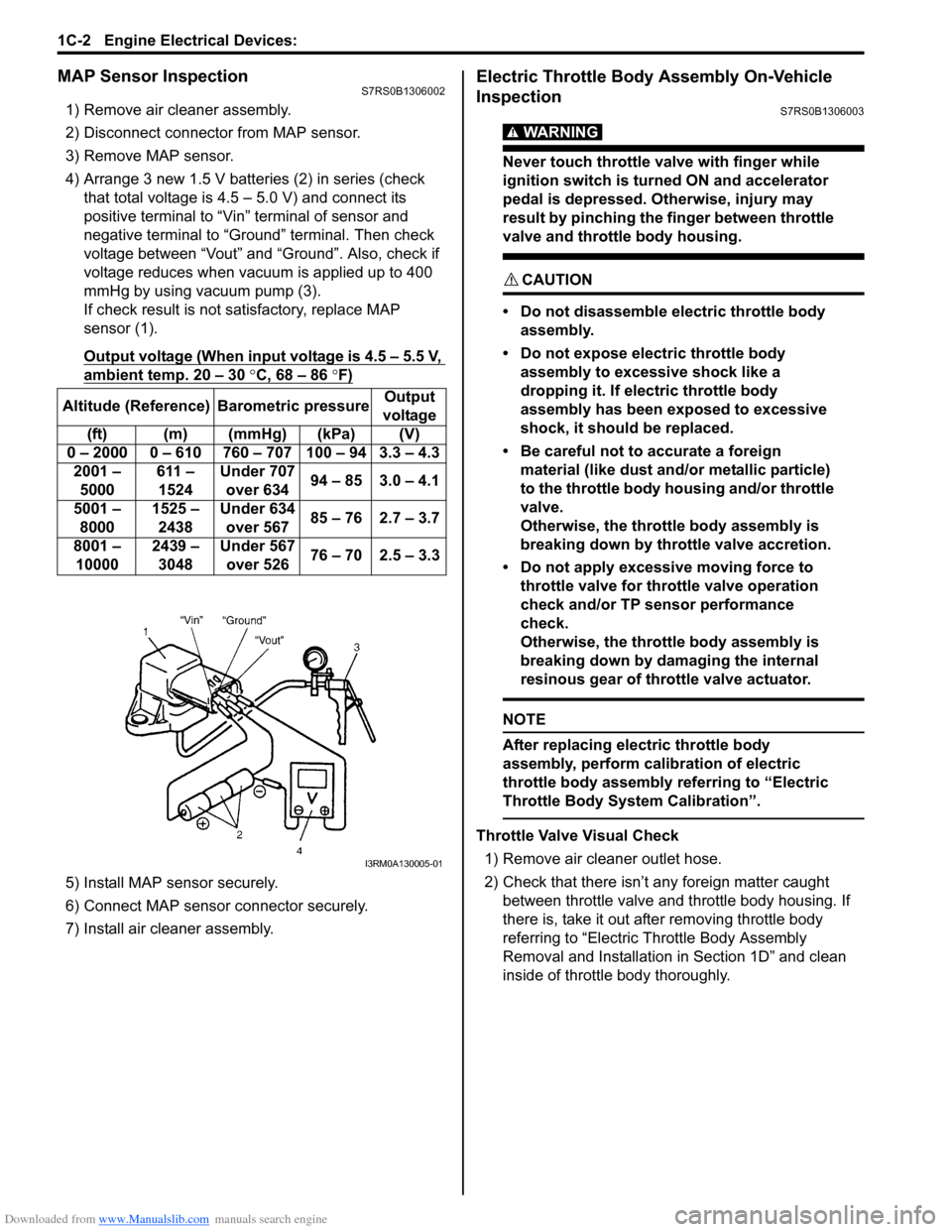
4) Arrange 3 new 1.5 V batteries (2) in series (check that total voltage is 4.5 – 5.0 V) and connect its
positive terminal to “Vin ” terminal of sensor and
negative terminal to “Ground” terminal. Then check
voltage between “Vout” and “Ground”. Also, check if
voltage reduces when vacuum is applied up to 400
mmHg by using vacuum pump (3).
If check result is not satisfactory, replace MAP
sensor (1).
Output voltage (When input voltage is 4.5 – 5.5 V,
ambient temp. 20 – 30 °C, 68 – 86 °F)
5) Install MAP sensor securely.
6) Connect MAP sensor connector securely.
7) Install air cleaner assembly.
Electric Throttle Body Assembly On-Vehicle
Inspection
S7RS0B1306003
WARNING!
Never touch throttle valve with finger while
ignition switch is turned ON and accelerator
pedal is depressed. Otherwise, injury may
result by pinching the finger between throttle
valve and throttle body housing.
CAUTION!
• Do not disassemble electric throttle body assembly.
• Do not expose electric throttle body assembly to excessive shock like a
dropping it. If electric throttle body
assembly has been exposed to excessive
shock, it should be replaced.
• Be careful not to accurate a foreign material (like dust and/ or metallic particle)
to the throttle body housing and/or throttle
valve.
Otherwise, the throttle body assembly is
breaking down by throttle valve accretion.
• Do not apply excessive moving force to throttle valve for thro ttle valve operation
check and/or TP sensor performance
check.
Otherwise, the throttle body assembly is
breaking down by damaging the internal
resinous gear of throttle valve actuator.
NOTE
After replacing electric throttle body
assembly, perform calibration of electric
throttle body assembly referring to “Electric
Throttle Body System Calibration”.
Throttle Valve Visual Check
1) Remove air cleaner outlet hose.
2) Check that there isn’t any foreign matter caught between throttle valve and throttle body housing. If
there is, take it out after removing throttle body
referring to “Electric Th rottle Body Assembly
Removal and Installation in Section 1D” and clean
inside of throttle body thoroughly.
Altitude (Reference) Barometric pressure
Output
voltage
(ft) (m) (mmHg) (kPa) (V)
0 – 2000 0 – 610 760 – 707 100 – 94 3.3 – 4.3 2001 – 5000 611 –
1524 Under 707
over 634 94 – 85 3.0 – 4.1
5001 – 8000 1525 –
2438 Under 634
over 567 85 – 76 2.7 – 3.7
8001 – 10000 2439 –
3048 Under 567
over 526 76 – 70 2.5 – 3.3
I3RM0A130005-01
Page 290 of 1496
Downloaded from www.Manualslib.com manuals search engine 1D-5 Engine Mechanical:
11) Connect negative cable at battery.
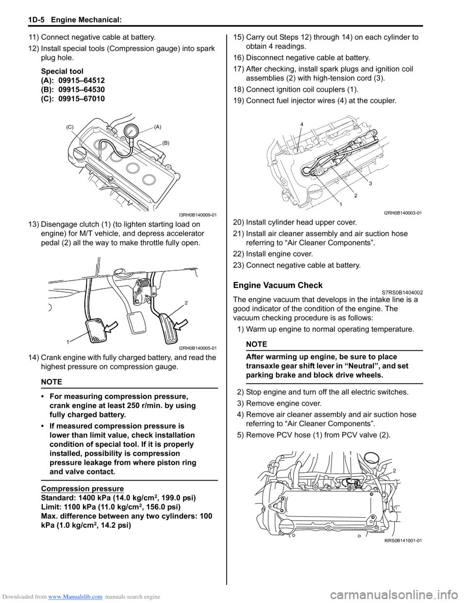
12) Install special tools (Compression gauge) into spark plug hole.
Special tool
(A): 09915–64512
(B): 09915–64530
(C): 09915–67010
13) Disengage clutch (1) (to lighten starting load on engine) for M/T vehicle, and depress accelerator
pedal (2) all the way to make throttle fully open.
14) Crank engine with fully charged battery, and read the highest pressure on compression gauge.
NOTE
• For measuring compression pressure, crank engine at least 250 r/min. by using
fully charged battery.
• If measured compression pressure is lower than limit value, check installation
condition of special tool. If it is properly
installed, possibility is compression
pressure leakage from where piston ring
and valve contact.
Compression pressure
Standard: 1400 kPa (14.0 kg/cm2, 199.0 psi)
Limit: 1100 kPa (11.0 kg/cm2, 156.0 psi)
Max. difference between any two cylinders: 100
kPa (1.0 kg/cm
2, 14.2 psi) 15) Carry out Steps 12) through 14) on each cylinder to
obtain 4 readings.
16) Disconnect negative cable at battery.
17) After checking, install spark plugs and ignition coil assemblies (2) with high-tension cord (3).
18) Connect ignition coil couplers (1).
19) Connect fuel injector wires (4) at the coupler.
20) Install cylinder head upper cover.
21) Install air cleaner assembly and air suction hose referring to “Air Cleaner Components”.
22) Install engine cover.
23) Connect negative cable at battery.
Engine Vacuum CheckS7RS0B1404002
The engine vacuum that develops in the intake line is a
good indicator of the condition of the engine. The
vacuum checking procedure is as follows:
1) Warm up engine to normal operating temperature.
NOTE
After warming up engine, be sure to place
transaxle gear shift lever in “Neutral”, and set
parking brake and block drive wheels.
2) Stop engine and turn off the all electric switches.
3) Remove engine cover.
4) Remove air cleaner assembly and air suction hose referring to “Air Cleaner Components”.
5) Remove PCV hose (1) from PCV valve (2).
(A)
(C)
(B)
I3RH0B140009-01
I2RH0B140005-01
I2RH0B140003-01
2
1
I6RS0B141001-01
Page 291 of 1496
Downloaded from www.Manualslib.com manuals search engine Engine Mechanical: 1D-6
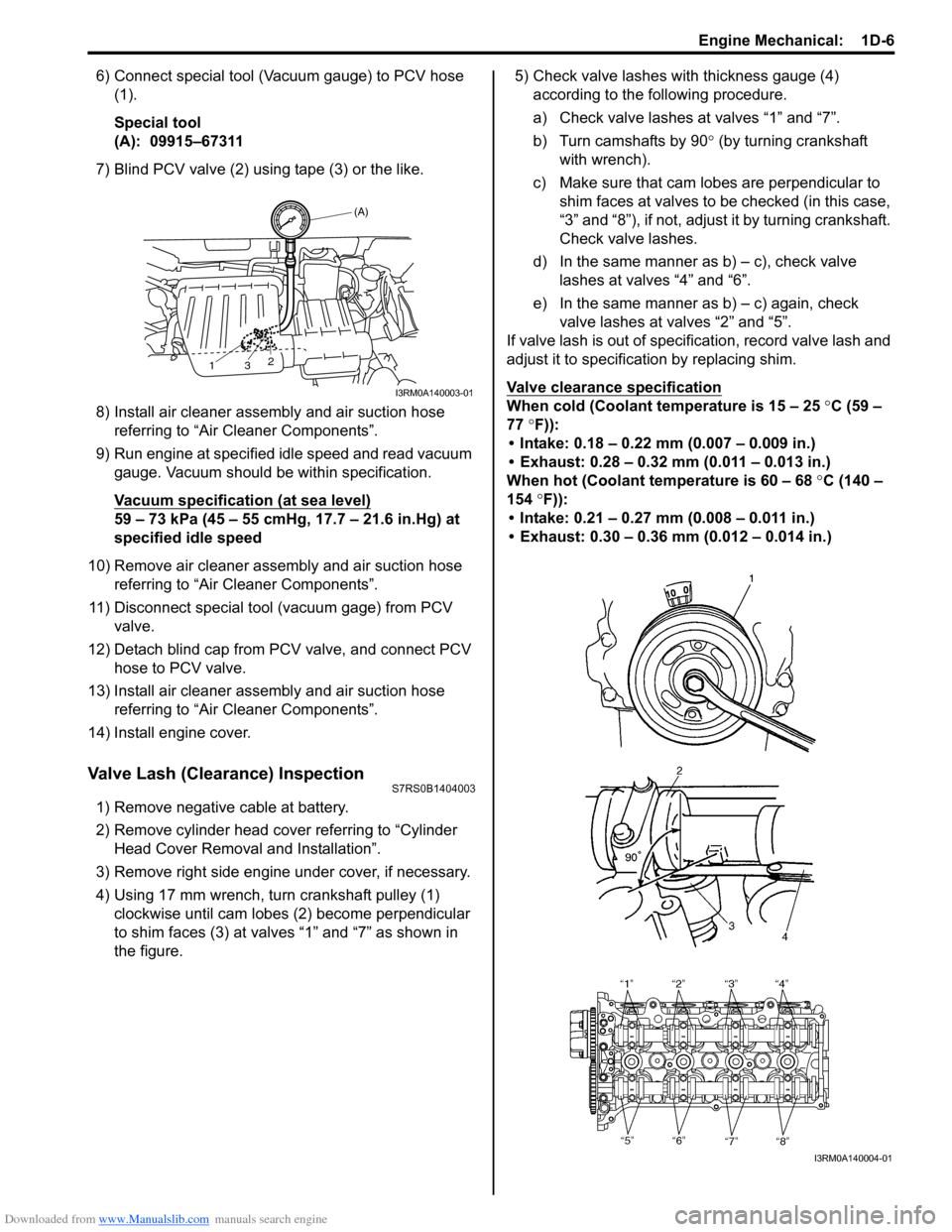
6) Connect special tool (Vacuum gauge) to PCV hose (1).
Special tool
(A): 09915–67311
7) Blind PCV valve (2) using tape (3) or the like.
8) Install air cleaner assembly and air suction hose referring to “Air Cleaner Components”.
9) Run engine at specified idle speed and read vacuum gauge. Vacuum should be within specification.
Vacuum specification (at sea level)
59 – 73 kPa (45 – 55 cmHg, 17.7 – 21.6 in.Hg) at
specified idle speed
10) Remove air cleaner assembly and air suction hose referring to “Air Cleaner Components”.
11) Disconnect special tool (vacuum gage) from PCV valve.
12) Detach blind cap from PCV valve, and connect PCV hose to PCV valve.
13) Install air cleaner assembly and air suction hose referring to “Air Cleaner Components”.
14) Install engine cover.
Valve Lash (Clearance) InspectionS7RS0B1404003
1) Remove negative cable at battery.
2) Remove cylinder head cover referring to “Cylinder Head Cover Removal and Installation”.
3) Remove right side engine under cover, if necessary.
4) Using 17 mm wrench, turn crankshaft pulley (1) clockwise until cam lobes (2) become perpendicular
to shim faces (3) at valves “1” and “7” as shown in
the figure. 5) Check valve lashes with thickness gauge (4)
according to the following procedure.
a) Check valve lashes at valves “1” and “7”.
b) Turn camshafts by 90 ° (by turning crankshaft
with wrench).
c) Make sure that cam lobes are perpendicular to shim faces at valves to be checked (in this case,
“3” and “8”), if not, adjust it by turning crankshaft.
Check valve lashes.
d) In the same manner as b) – c), check valve
lashes at valves “4” and “6”.
e) In the same manner as b) – c) again, check valve lashes at valves “2” and “5”.
If valve lash is out of specification, record valve lash and
adjust it to specification by replacing shim.
Valve clearance specification
When cold (Coolant te mperature is 15 – 25 °C (59 –
77 °F)):
• Intake: 0.18 – 0.22 mm (0.007 – 0.009 in.)
• Exhaust: 0.28 – 0.32 mm (0.011 – 0.013 in.)
When hot (Coolant temperature is 60 – 68 °C (140 –
154 °F)):
• Intake: 0.21 – 0.27 mm (0.008 – 0.011 in.)
• Exhaust: 0.30 – 0.36 mm (0.012 – 0.014 in.)
(A)
13 2
I3RM0A140003-01
I3RM0A140004-01
Page 514 of 1496
Downloaded from www.Manualslib.com manuals search engine 4A-16 Brake Control System and Diagnosis:
Booster Operation InspectionS7RS0B4106016
There are two ways to perform this inspection, with and
without a tester. Ordinarily, it is possible to roughly
determine its condition without using a tester.
NOTE
For this check, make su re that no air is in
hydraulic line.
Check Air Tightness
1) Start engine.
2) Stop engine after running for 1 to 2 minutes.
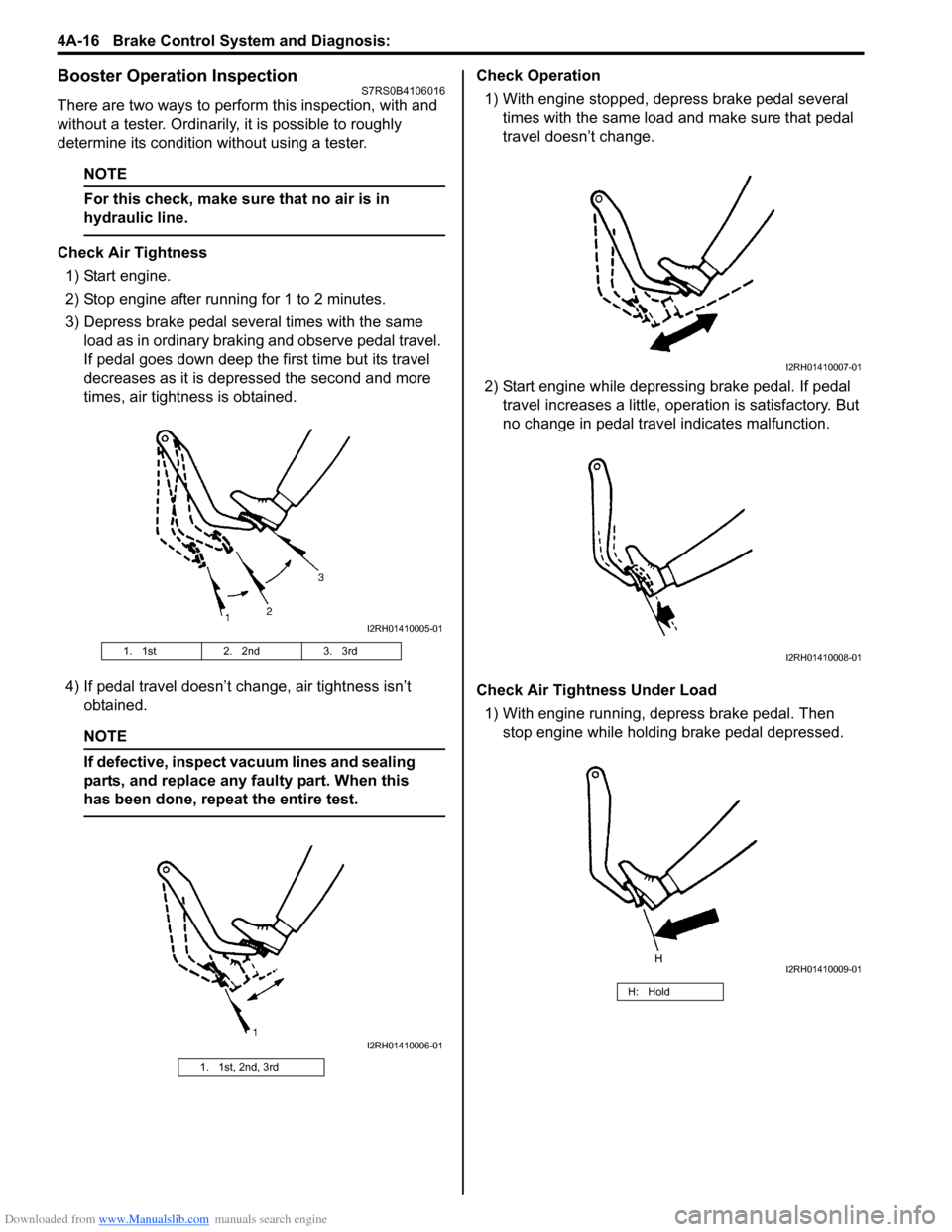
3) Depress brake pedal several times with the same load as in ordinary braking and observe pedal travel.
If pedal goes down deep the first time but its travel
decreases as it is depressed the second and more
times, air tightness is obtained.
4) If pedal travel doesn’t change, air tightness isn’t obtained.
NOTE
If defective, inspect vacuum lines and sealing
parts, and replace any faulty part. When this
has been done, repeat the entire test.
Check Operation
1) With engine stopped, depress brake pedal several times with the same load and make sure that pedal
travel doesn’t change.
2) Start engine while depressing brake pedal. If pedal travel increases a little, operation is satisfactory. But
no change in pedal travel indicates malfunction.
Check Air Tightness Under Load 1) With engine running, depress brake pedal. Then stop engine while holding brake pedal depressed.
1. 1st 2. 2nd3. 3rd
1. 1st, 2nd, 3rd
I2RH01410005-01
I2RH01410006-01
H: Hold
I2RH01410007-01
I2RH01410008-01
I2RH01410009-01
Page 966 of 1496
Downloaded from www.Manualslib.com manuals search engine 7B-18 Air Conditioning System: Manual Type
When replacing other parts
Replenish the following amount of oil to compressor.
Amount of compressor oil to be replenished
Evaporator: 25 cm3 (25 ml, 0.85 US. oz, 0.88 Imp. oz)
Condenser: 15 cm3 (15 ml, 0.51 US. oz, 0.53 Imp. oz)
Receiver/dryer: 10 cm3 (10 ml, 0.34 US. oz, 0.35 lmp.
oz)
Hoses: 10 cm
3 (10 ml, 0.34 US. oz, 0.35 Imp. oz) each
Pipes: 10 cm3 (10 ml, 0.34 US. oz, 0.35 Imp. oz) each
Evacuation
CAUTION!
Do not evacuate before recovering
refrigerant in A/C system.
NOTE
Once air conditioning system circuit is
opened (exposed) to atmospheric air, system
must be evacuated by using a vacuum pump.
The A/C system should be attached with a
manifold gauge set, and should be evacuated
for approximately 15 minutes.
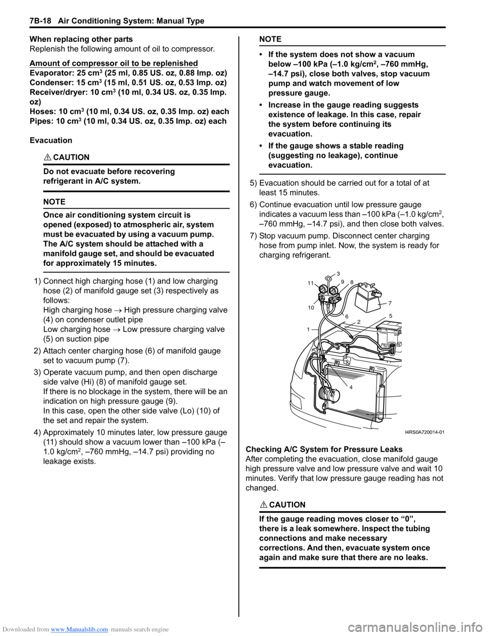
1) Connect high charging hose (1) and low charging hose (2) of manifold gauge set (3) respectively as
follows:
High charging hose → High pressure charging valve
(4) on condenser outlet pipe
Low charging hose → Low pressure charging valve
(5) on suction pipe
2) Attach center charging hose (6) of manifold gauge set to vacuum pump (7).
3) Operate vacuum pump, and then open discharge
side valve (Hi) (8) of manifold gauge set.
If there is no blockage in the system, there will be an
indication on high pressure gauge (9).
In this case, open the other side valve (Lo) (10) of
the set and repair the system.
4) Approximately 10 minutes later, low pressure gauge (11) should show a vacuum lower than –100 kPa (–
1.0 kg/cm
2, –760 mmHg, –14.7 psi) providing no
leakage exists.
NOTE
• If the system does not show a vacuum below –100 kPa (–1.0 kg/cm
2, –760 mmHg,
–14.7 psi), close both valves, stop vacuum
pump and watch movement of low
pressure gauge.
• Increase in the gauge reading suggests existence of leakage. In this case, repair
the system before continuing its
evacuation.
• If the gauge shows a stable reading (suggesting no leakage), continue
evacuation.
5) Evacuation should be carried out for a total of at least 15 minutes.
6) Continue evacuation until low pressure gauge indicates a vacuum less than –100 kPa (–1.0 kg/cm
2,
–760 mmHg, –14.7 psi), and then close both valves.
7) Stop vacuum pump. Disconnect center charging hose from pump inlet. No w, the system is ready for
charging refrigerant.
Checking A/C System for Pressure Leaks
After completing the evacuation, close manifold gauge
high pressure valve and low pressure valve and wait 10
minutes. Verify that low pressure gauge reading has not
changed.
CAUTION!
If the gauge reading moves closer to “0”,
there is a leak somewhere. Inspect the tubing
connections and make necessary
corrections. And then, evacuate system once
again and make sure that there are no leaks.
7 5
2
4
1
10
11
3
9 8
6
I4RS0A720014-01
Page 1172 of 1496
Downloaded from www.Manualslib.com manuals search engine 9A-1 Wiring Systems:
Body, Cab and Accessories
Wiring Systems
Precautions
Cautions in Body Electrical System ServicingS7RS0B9100001
When servicing the electric systems, observe the cautions described in “Precautions for Electrical Circuit Service in
Section 00” to protect electrical parts and to prevent a fire.
General Description
AbbreviationsS7RS0B9101001
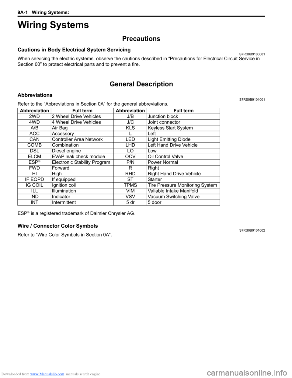
Refer to the “Abbreviations in Sect ion 0A” for the general abbreviations.
ESP
® is a registered trademark of Daimler Chrysler AG.
Wire / Connector Color SymbolsS7RS0B9101002
Refer to “Wire Color Sy mbols in Section 0A”.
Abbreviation Full term Abbreviation Full term
2WD 2 Wheel Drive Vehicles J/B Junction block
4WD 4 Wheel Drive Vehicles J/C Joint connectorA/B Air Bag KLS Keyless Start System
ACC Accessory L Left
CAN Controller Area Network LED Light Emitting Diode
COMB Combination LHD Left Hand Drive Vehicle DSL Diesel engine LO Low
ELCM EVAP leak check module OCV Oil Control Valve ESP
®Electronic Stability Program P/N Power Normal
FWD Forward R Right HI High RHD Right Hand Drive Vehicle
IF EQPD If equipped ST Starter IG COIL Ignition coil TPMS Tire Pressure Monitoring System ILL Illumination VIM Valiable Intake Manifold
IND Indicator VSV Vacuum Switching Valve INT Intermittent 5 dr 5 door