Side mirror SUZUKI SWIFT 2006 2.G Service User Guide
[x] Cancel search | Manufacturer: SUZUKI, Model Year: 2006, Model line: SWIFT, Model: SUZUKI SWIFT 2006 2.GPages: 1496, PDF Size: 34.44 MB
Page 1332 of 1496
Downloaded from www.Manualslib.com manuals search engine 9E-5 Glass / Windows / Mirrors:
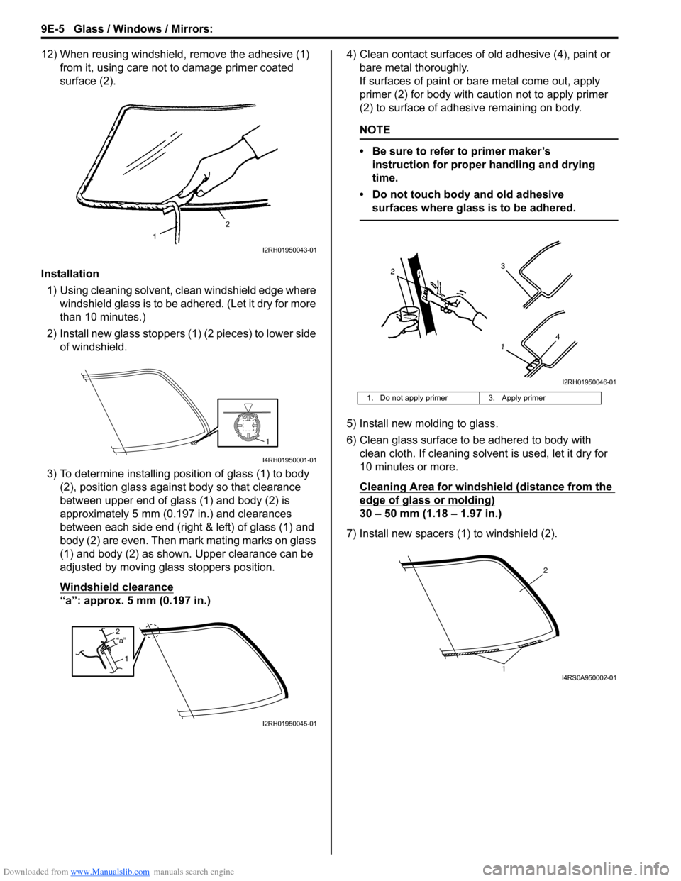
12) When reusing windshield, remove the adhesive (1) from it, using care not to damage primer coated
surface (2).
Installation 1) Using cleaning solvent, clean windshield edge where windshield glass is to be adhered. (Let it dry for more
than 10 minutes.)
2) Install new glass stoppers (1) (2 pieces) to lower side of windshield.
3) To determine installing position of glass (1) to body (2), position glass against body so that clearance
between upper end of glass (1) and body (2) is
approximately 5 mm (0.197 in.) and clearances
between each side end (right & left) of glass (1) and
body (2) are even. Then mark mating marks on glass
(1) and body (2) as shown. Upper clearance can be
adjusted by moving glass stoppers position.
Windshield clearance
“a”: approx. 5 mm (0.197 in.) 4) Clean contact surfaces of old adhesive (4), paint or
bare metal thoroughly.
If surfaces of paint or ba re metal come out, apply
primer (2) for body with caution not to apply primer
(2) to surface of adhesive remaining on body.
NOTE
• Be sure to refer to primer maker’s instruction for proper handling and drying
time.
• Do not touch body and old adhesive surfaces where glass is to be adhered.
5) Install new molding to glass.
6) Clean glass surface to be adhered to body with clean cloth. If cleaning solvent is used, let it dry for
10 minutes or more.
Cleaning Area for windshie ld (distance from the
edge of glass or molding)
30 – 50 mm (1.18 – 1.97 in.)
7) Install new spacers (1) to windshield (2).
I2RH01950043-01
1
I4RH01950001-01
2
1“a”
I2RH01950045-01
1. Do not apply primer 3. Apply primer
I2RH01950046-01
2
1I4RS0A950002-01
Page 1333 of 1496
Downloaded from www.Manualslib.com manuals search engine Glass / Windows / Mirrors: 9E-6
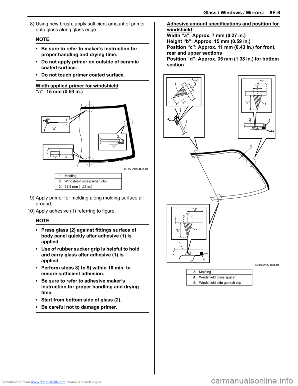
8) Using new brush, apply sufficient amount of primer onto glass along glass edge.
NOTE
• Be sure to refer to maker’s instruction for
proper handling and drying time.
• Do not apply primer on outside of ceramic coated surface.
• Do not touch primer coated surface.
Width applied primer for windshield
“a”: 15 mm (0.59 in.)
9) Apply primer for molding along molding surface all around.
10) Apply adhesive (1) referring to figure.
NOTE
• Press glass (2) against fittings surface of body panel quickly after adhesive (1) is
applied.
• Use of rubber sucker gr ip is helpful to hold
and carry glass after adhesive (1) is
applied.
• Perform steps 8) to 9) within 10 min. to ensure sufficient adhesion.
• Be sure to refer to adhesive maker’s instruction for proper handling and drying
time.
• Start from bottom side of glass (2).
• Be careful not to damage primer.
Adhesive amount specifications and position for
windshield
Width “a”: Approx. 7 mm (0.27 in.)
Height “b”: Approx. 15 mm (0.59 in.)
Position “c”: Approx. 11 mm (0.43 in.) for front,
rear and upper sections
Position “d”: Approx. 35 mm (1.38 in.) for bottom
section
1. Molding
2. Windshield side garnish clip
3. 32.5 mm (1.28 in.)
“a”
1
“a”
“a”
2
3
I4RS0A950003-01
3. Molding
4. Windshield glass spacer
5. Windshield side garnish clip
2
2
4
1
“b” “d”
“b”
“c”
2
1
“a”
3
2
1
“b”
“c”
5
“a”
“a”
I4RS0A950004-01
Page 1340 of 1496
Downloaded from www.Manualslib.com manuals search engine 9E-13 Glass / Windows / Mirrors:
Rear End Door Window ComponentsS7RS0B9506010
Rear End Door Glass Removal and InstallationS7RS0B9506011
Refer to “Windshield Removal and Installation” as
removal and installation procedures are basically the
same. However, note the following.
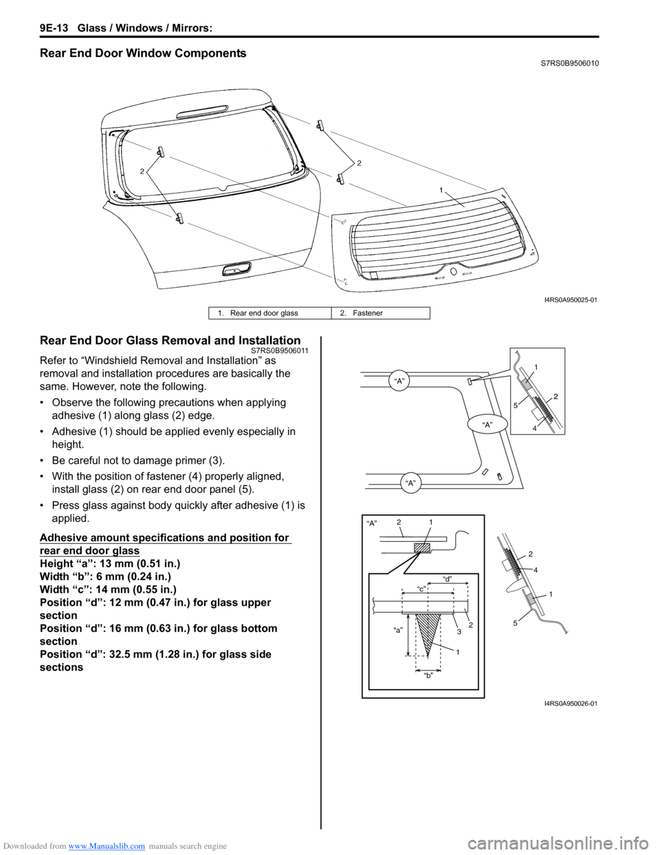
• Observe the following precautions when applying adhesive (1) along glass (2) edge.
• Adhesive (1) should be app lied evenly especially in
height.
• Be careful not to damage primer (3).
• With the position of fastener (4) properly aligned, install glass (2) on rear end door panel (5).
• Press glass against body quickly after adhesive (1) is applied.
Adhesive amount specifications and position for
rear end door glass
Height “a”: 13 mm (0.51 in.)
Width “b”: 6 mm (0.24 in.)
Width “c”: 14 mm (0.55 in.)
Position “d”: 12 mm (0.47 in.) for glass upper
section
Position “d”: 16 mm (0.63 in.) for glass bottom
section
Position “d”: 32.5 mm (1.28 in.) for glass side
sections
I4RS0A950025-01
1. Rear end door glass 2. Fastener
“A”
“A”
“A”
“A”
“c”“d”
“a” “b”
21
2
3
1
2
1
1
2
5
2
4
4
5
I4RS0A950026-01
Page 1342 of 1496
Downloaded from www.Manualslib.com manuals search engine 9E-15 Glass / Windows / Mirrors:
Rear End Door Window Defogger Wire
Inspection
S7RS0B9506014
NOTE
• When cleaning rear end door window glass, use a dry cloth to wipe it along heat
wire (1) direction.
• When cleaning glass, do not use detergent or abrasive-containing glass cleaner.
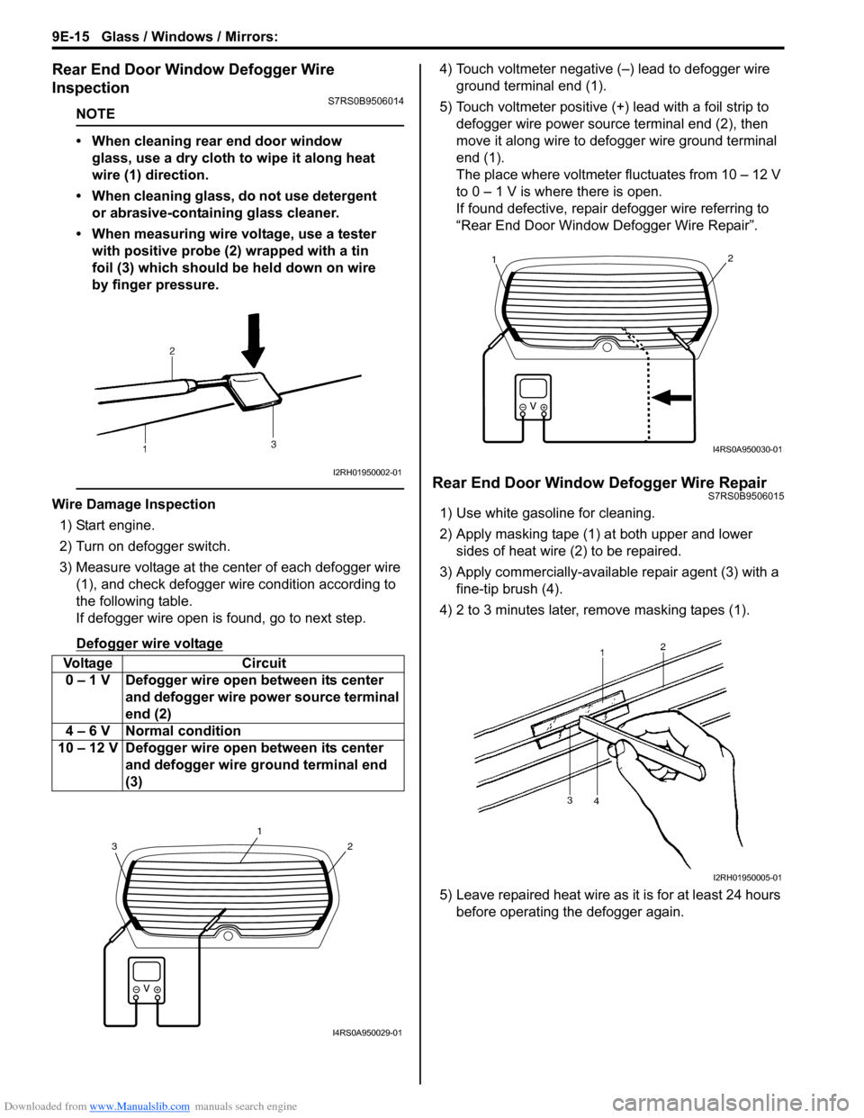
• When measuring wire voltage, use a tester with positive probe (2) wrapped with a tin
foil (3) which should be held down on wire
by finger pressure.
Wire Damage Inspection
1) Start engine.
2) Turn on defogger switch.
3) Measure voltage at the center of each defogger wire (1), and check defogger wire condition according to
the following table.
If defogger wire open is found, go to next step.
Defogger wire voltage
4) Touch voltmeter negative (–) lead to defogger wire ground terminal end (1).
5) Touch voltmeter positive (+) lead with a foil strip to defogger wire power source terminal end (2), then
move it along wire to defogger wire ground terminal
end (1).
The place where voltmeter fluctuates from 10 – 12 V
to 0 – 1 V is where there is open.
If found defective, repair defogger wire referring to
“Rear End Door Window Defogger Wire Repair”.
Rear End Door Window Defogger Wire RepairS7RS0B9506015
1) Use white gasoline for cleaning.
2) Apply masking tape (1) at both upper and lower sides of heat wire (2) to be repaired.
3) Apply commercially-available repair agent (3) with a fine-tip brush (4).
4) 2 to 3 minutes later, remove masking tapes (1).
5) Leave repaired heat wire as it is for at least 24 hours before operating the defogger again.
Voltage Circuit
0 – 1 V Defogger wire open between its center and defogger wire power source terminal
end (2)
4 – 6 V Normal condition
10 – 12 V Defogger wire open between its center and defogger wire ground terminal end
(3)
I2RH01950002-01
2
1
3
I4RS0A950029-01
21
I4RS0A950030-01
I2RH01950005-01
Page 1343 of 1496
Downloaded from www.Manualslib.com manuals search engine Glass / Windows / Mirrors: 9E-16
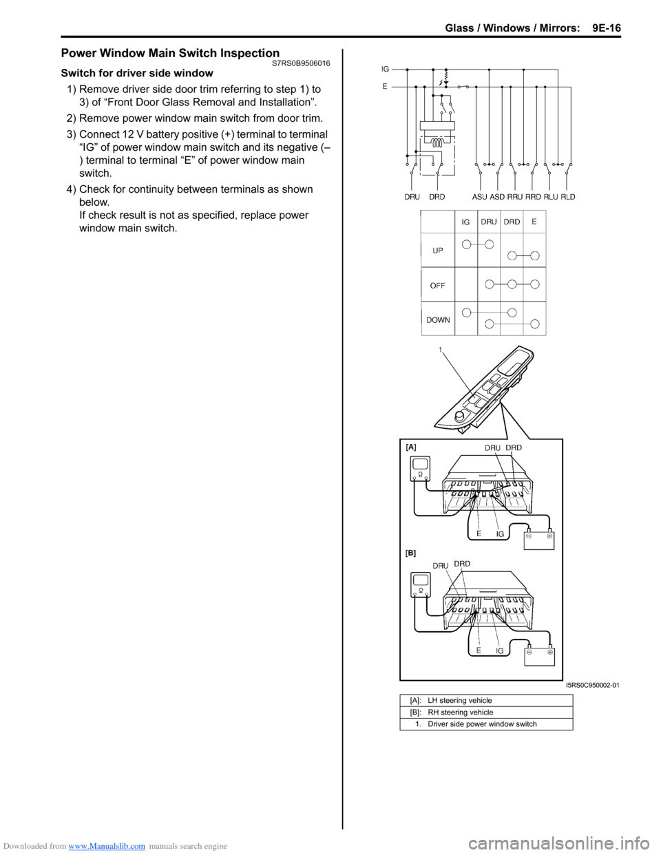
Power Window Main Switch InspectionS7RS0B9506016
Switch for driver side window 1) Remove driver side door trim referring to step 1) to 3) of “Front Door Glass Removal and Installation”.
2) Remove power window main switch from door trim.
3) Connect 12 V battery positive (+) terminal to terminal “IG” of power window main switch and its negative (–
) terminal to terminal “E” of power window main
switch.
4) Check for continuity between terminals as shown below.
If check result is not as specified, replace power
window main switch.
[A]: LH steering vehicle
[B]: RH steering vehicle
1. Driver side power window switch
I5RS0C950002-01
Page 1344 of 1496
Downloaded from www.Manualslib.com manuals search engine 9E-17 Glass / Windows / Mirrors:
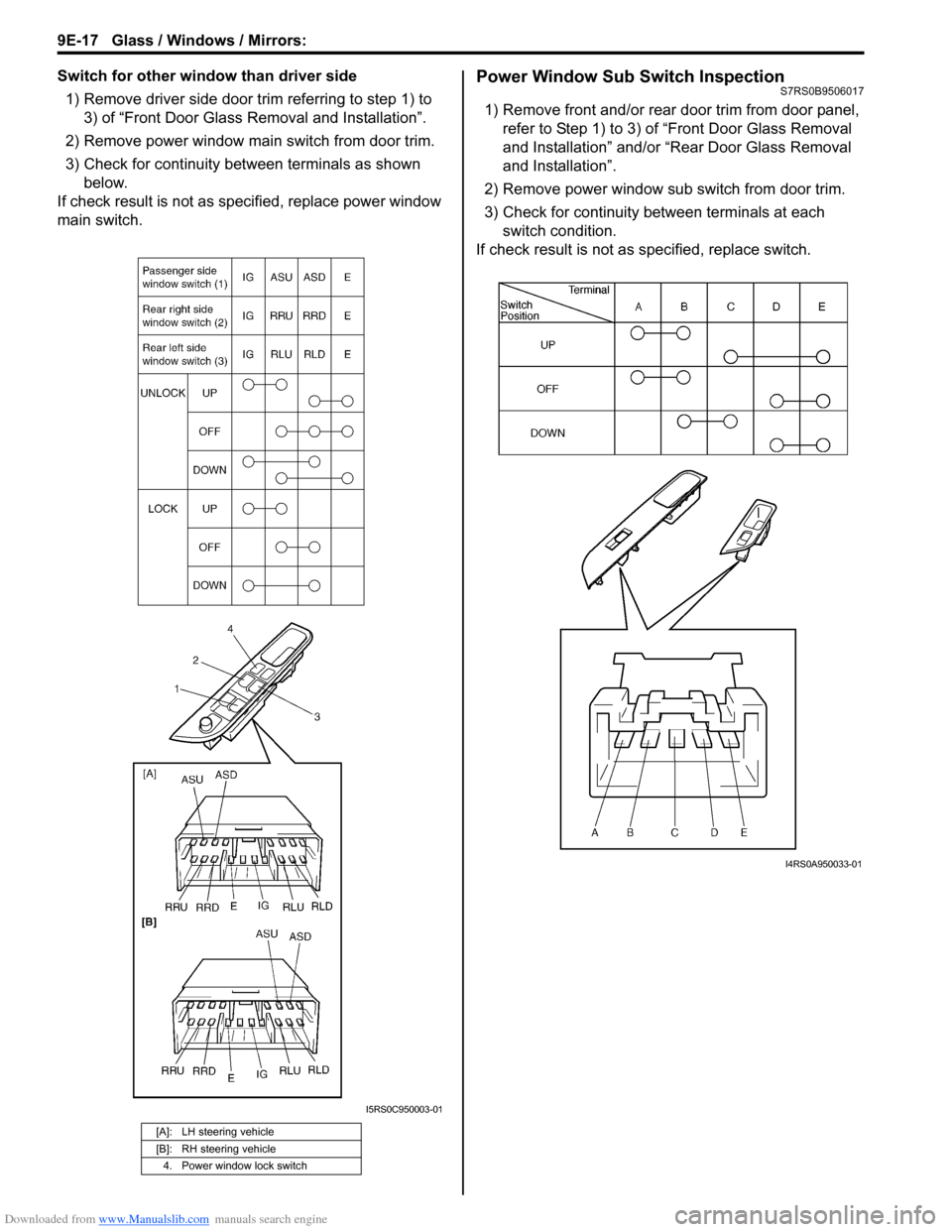
Switch for other window than driver side1) Remove driver side door trim referring to step 1) to 3) of “Front Door Glass Removal and Installation”.
2) Remove power window main switch from door trim.
3) Check for continuity between terminals as shown below.
If check result is not as sp ecified, replace power window
main switch.Power Window Sub Switch InspectionS7RS0B9506017
1) Remove front and/or rear door trim from door panel, refer to Step 1) to 3) of “Front Door Glass Removal
and Installation” and/or “Rear Door Glass Removal
and Installation”.
2) Remove power window sub switch from door trim.
3) Check for continuity between terminals at each switch condition.
If check result is not as specified, replace switch.
[A]: LH steering vehicle
[B]: RH steering vehicle
4. Power window lock switch
I5RS0C950003-01
I4RS0A950033-01
Page 1345 of 1496
Downloaded from www.Manualslib.com manuals search engine Glass / Windows / Mirrors: 9E-18
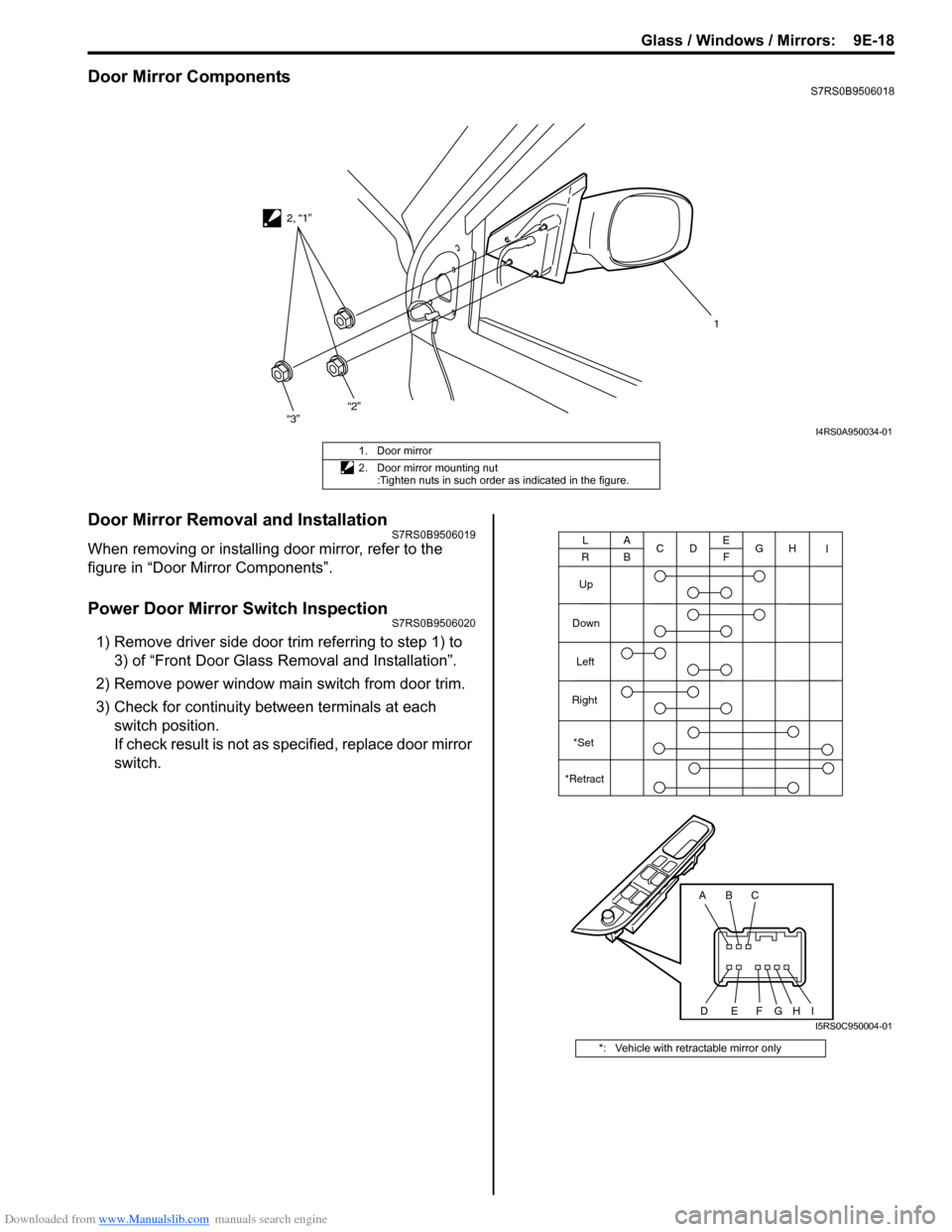
Door Mirror ComponentsS7RS0B9506018
Door Mirror Removal and InstallationS7RS0B9506019
When removing or installing door mirror, refer to the
figure in “Door Mirror Components”.
Power Door Mirror Switch InspectionS7RS0B9506020
1) Remove driver side door trim referring to step 1) to 3) of “Front Door Glass Removal and Installation”.
2) Remove power window main switch from door trim.
3) Check for continuity between terminals at each switch position.
If check result is not as specified, replace door mirror
switch.
1
2, “1”
“3”
“2”
I4RS0A950034-01
1. Door mirror
2. Door mirror mounting nut
:Tighten nuts in such order as indicated in the figure.
*: Vehicle with retractable mirror only
ABC
DEFG
A
B C
D E
F G
Up
Down Left
Right
L
RH I
*Set
*Retract
HII5RS0C950004-01
Page 1346 of 1496
Downloaded from www.Manualslib.com manuals search engine 9E-19 Glass / Windows / Mirrors:
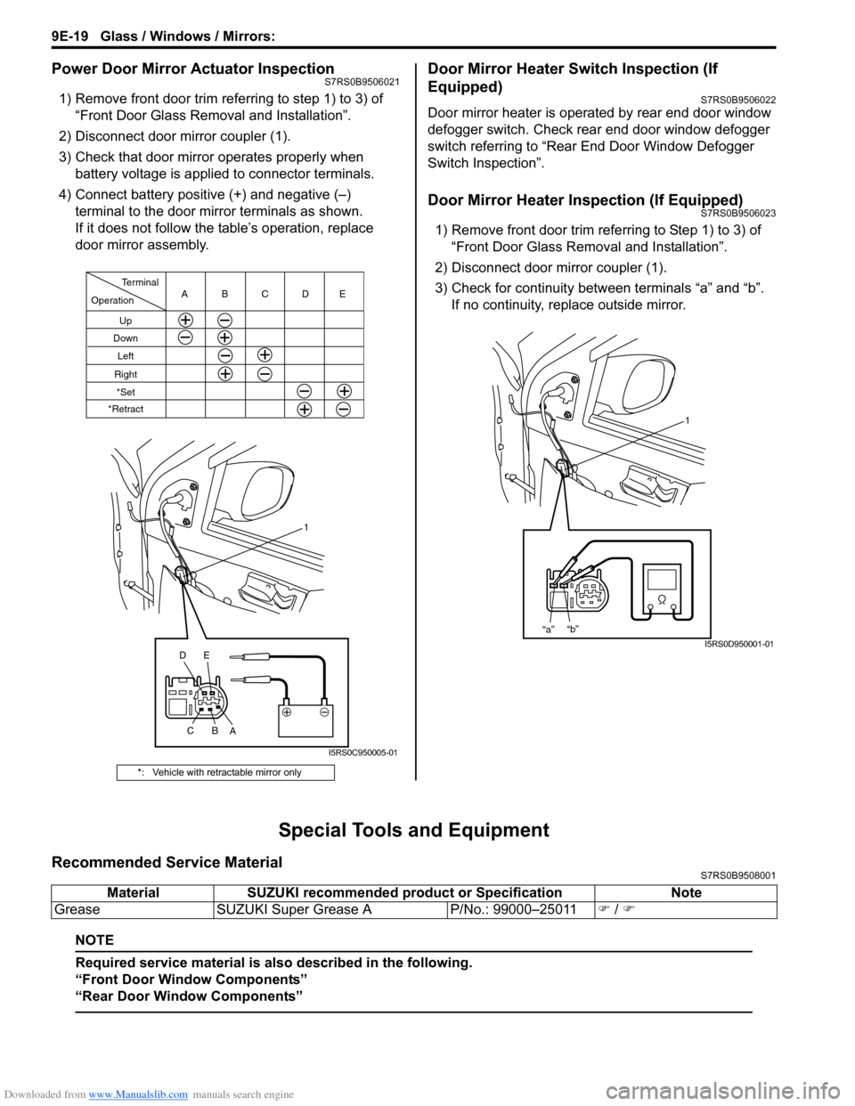
Power Door Mirror Actuator InspectionS7RS0B9506021
1) Remove front door trim referring to step 1) to 3) of “Front Door Glass Removal and Installation”.
2) Disconnect door mirror coupler (1).
3) Check that door mirror operates properly when battery voltage is applied to connector terminals.
4) Connect battery positive (+) and negative (–) terminal to the door mirror terminals as shown.
If it does not follow the table’s operation, replace
door mirror assembly.
Door Mirror Heater Switch Inspection (If
Equipped)
S7RS0B9506022
Door mirror heater is operated by rear end door window
defogger switch. Check rear end door window defogger
switch referring to “Rear End Door Window Defogger
Switch Inspection”.
Door Mirror Heater Inspection (If Equipped)S7RS0B9506023
1) Remove front door trim refe rring to Step 1) to 3) of
“Front Door Glass Removal and Installation”.
2) Disconnect door mirror coupler (1).
3) Check for continuity between terminals “a” and “b”. If no continuity, replace outside mirror.
Special Tools and Equipment
Recommended Service MaterialS7RS0B9508001
NOTE
Required service material is also described in the following.
“Front Door Window Components”
“Rear Door Window Components”
*: Vehicle with retractable mirror only
Operation
Terminal
Up
Down
Left
RightCBA
1
C B
A
*Set
*Retract
DE
DE
I5RS0C950005-01
1
“a” “b”
I5RS0D950001-01
Material
SUZUKI recommended product or Specification Note
Grease SUZUKI Super Grease A P/No.: 99000–25011�) / �)
Page 1352 of 1496
Downloaded from www.Manualslib.com manuals search engine 9F-6 Security and Locks:
Repair Instructions
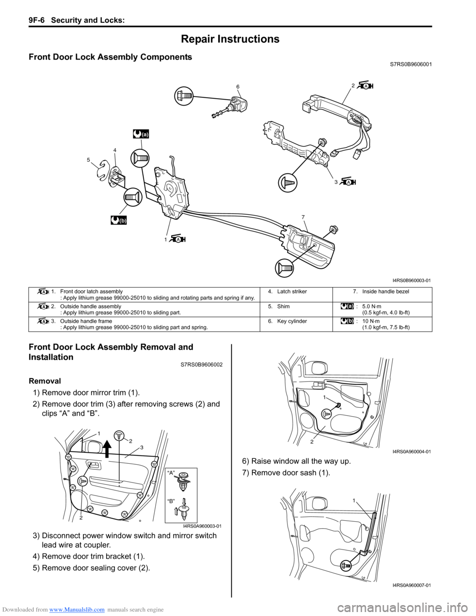
Front Door Lock Assembly ComponentsS7RS0B9606001
Front Door Lock Assembly Removal and
Installation
S7RS0B9606002
Removal1) Remove door mirror trim (1).
2) Remove door trim (3) after removing screws (2) and clips “A” and “B”.
3) Disconnect power window s witch and mirror switch
lead wire at coupler.
4) Remove door trim bracket (1).
5) Remove door sealing cover (2). 6) Raise window all the way up.
7) Remove door sash (1).
(a)
(b)
6
3
7
1
4
5
2
I4RS0B960003-01
1. Front door latch assembly : Apply lithium grease 99000-25010 to sliding and rotating parts and spring if any. 4. Latch striker 7. Inside handle bezel
2. Outside handle assembly : Apply lithium grease 99000-25010 to sliding part. 5. Shim : 5.0 N
⋅m
(0.5 kgf-m, 4.0 lb-ft)
3. Outside handle frame : Apply lithium grease 99000-25010 to sliding part and spring. 6. Key cylinder : 10 N⋅m
(1.0 kgf-m, 7.5 lb-ft)
“B”
“A”
“B”
“A”
“B”“A”
“A”
“A”“A”“A”
12
2 3
I4RS0A960003-01
1
2
I4RS0A960004-01
1
I4RS0A960007-01
Page 1367 of 1496
Downloaded from www.Manualslib.com manuals search engine Interior Trim: 9H-1
Body, Cab and Accessories
Interior Trim
Repair Instructions
Floor Carpet Removal and InstallationS7RS0B9806001
WARNING!
Refer to “Air Bag Warning in Section 00”
before starting service work.
Removal1) Remove front seats and rear seats referring to “Front Seat Removal and Installa tion in Section 9G” and
“Rear Seat Removal and Installation in Section 9G”.
2) Remove seat belt lower anchor bolt.
3) Remove dash side trims, fr ont side sill scuffs, center
pillar inner lower trims, qu arter inner front trims and
rear side sill scuffs.
4) Remove console box.
5) Remove floor carpet.
Installation
Reverse removal sequence to install floor carpet, noting
the following instruction.
• For tightening torque of rear seat mounting bolt, refer to “Rear Seat Components in Section 9G”.
• For tightening torque of front seat mounting bolt, refer to “Front Seat Components in Section 9G”.
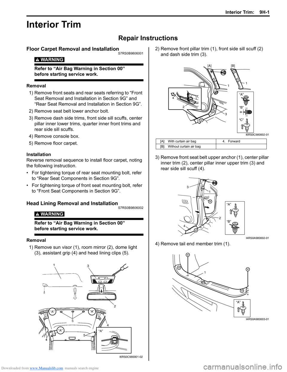
Head Lining Removal and InstallationS7RS0B9806002
WARNING!
Refer to “Air Bag Warning in Section 00”
before starting service work.
Removal
1) Remove sun visor (1), room mirror (2), dome light (3), assistant grip (4) and head lining clips (5). 2) Remove front pillar trim (1
), front side sill scuff (2)
and dash side trim (3).
3) Remove front seat belt u pper anchor (1), center pillar
inner trim (2), center pillar inner upper trim (3) and
rear side sill scuff (4).
4) Remove tail end member trim (1).
I6RS0C980001-02
[A]: With curtain air bag 4. Forward
[B]: Without curtain air bag
“A”“A”
“A”
2
4
1
3
“A”
“A”
1
[B]
[A]
“B”“B”
“C”“C”
I6RS0C980002-01
“A”
“B”
“A”
“B”
1
3
2
4
I4RS0A980002-01
“A”
“A”
“A”
“A”“A”1
I4RS0A980003-01