Suzuki scan tool SUZUKI SWIFT 2006 2.G Service User Guide
[x] Cancel search | Manufacturer: SUZUKI, Model Year: 2006, Model line: SWIFT, Model: SUZUKI SWIFT 2006 2.GPages: 1496, PDF Size: 34.44 MB
Page 266 of 1496
Downloaded from www.Manualslib.com manuals search engine 1A-216 Engine General Information and Diagnosis:
Repair Instructions
Idle Speed and IAC Throttle Valve Opening
Inspection
S7RS0B1106001
Before idle speed check, make sure of the following.
• Lead wires and hoses of electronic fuel injection and engine and emission control systems are connected
securely.
• Valve lash is checked according to maintenance schedule.
• Ignition timing is within specification.
• All accessories (wipers, heater, lights, A/C, etc.) are out of service.
• Air cleaner has been properly installed and is in good condition.
• No abnormal air drawn in from air intake system.
After all items are confirmed, check idle speed and IAC
duty as follows.
NOTE
Before starting engine, place transmission
gear shift lever in “Neutral” (shift selector
lever to “P” range for A/T vehicle), and set
parking brake and block drive wheels.
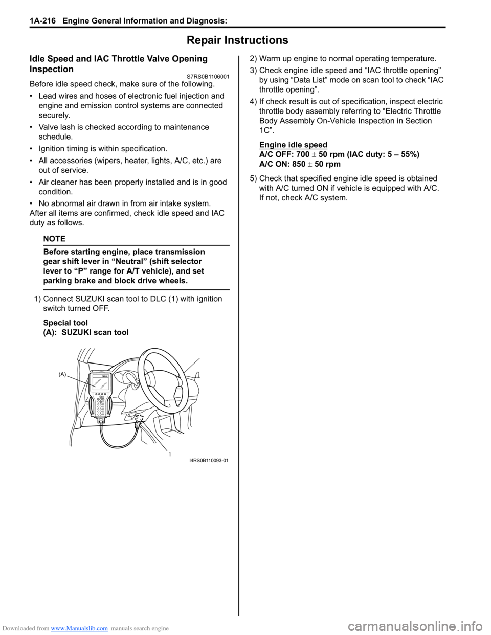
1) Connect SUZUKI scan tool to DLC (1) with ignition
switch turned OFF.
Special tool
(A): SUZUKI scan tool 2) Warm up engine to normal operating temperature.
3) Check engine idle speed and “IAC throttle opening”
by using “Data List” mode on scan tool to check “IAC
throttle opening”.
4) If check result is out of sp ecification, inspect electric
throttle body assembly referring to “Electric Throttle
Body Assembly On-Vehicle Inspection in Section
1C”.
Engine idle speed
A/C OFF: 700 ± 50 rpm (IAC duty: 5 – 55%)
A/C ON: 850 ± 50 rpm
5) Check that specified engine idle speed is obtained with A/C turned ON if vehi cle is equipped with A/C.
If not, check A/C system.
(A)
1
I4RS0B110093-01
Page 267 of 1496
Downloaded from www.Manualslib.com manuals search engine Engine General Information and Diagnosis: 1A-217
Special Tools and Equipment
Special ToolS7RS0B1108001
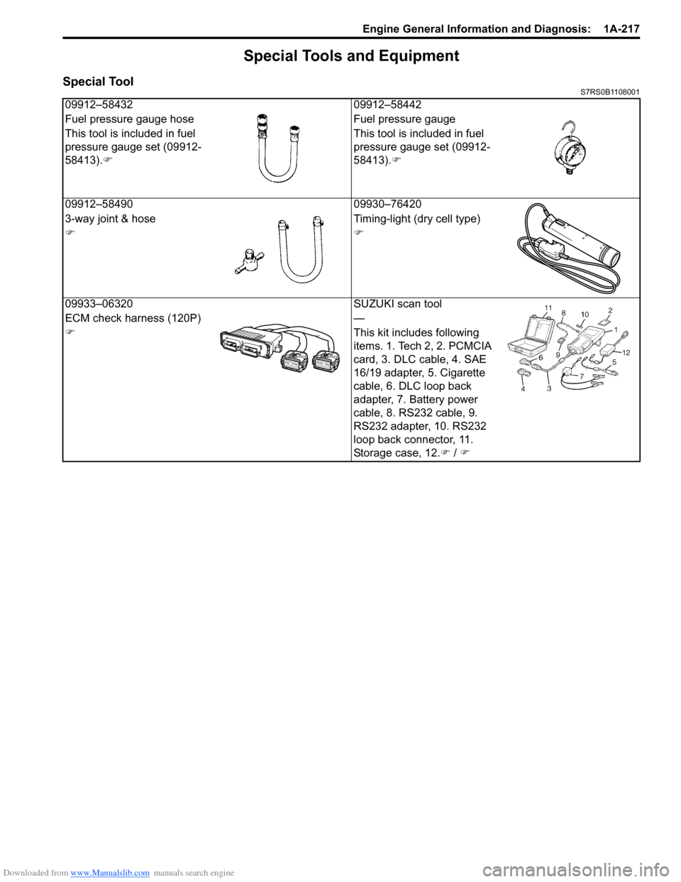
09912–5843209912–58442
Fuel pressure gauge hose Fuel pressure gauge
This tool is included in fuel
pressure gauge set (09912-
58413). �) This tool is included in fuel
pressure gauge set (09912-
58413).
�)
09912–58490 09930–76420
3-way joint & hose Timing-light (dry cell type)
�)�)
09933–06320 SUZUKI scan tool
ECM check harness (120P) —
�) This kit includes following
items. 1. Tech 2, 2. PCMCIA
card, 3. DLC cable, 4. SAE
16/19 adapter, 5. Cigarette
cable, 6. DLC loop back
adapter, 7. Battery power
cable, 8. RS232 cable, 9.
RS232 adapter, 10. RS232
loop back connector, 11.
Storage case, 12.�) / �)
Page 268 of 1496
Downloaded from www.Manualslib.com manuals search engine 1B-1 Aux. Emission Control Devices:
Engine
Aux. Emission Control Devices
Diagnostic Information and Procedures
EGR System InspectionS7RS0B1204001
1) Connect SUZUKI scan tool to data link connector (DLC) with ignition switch turned OFF.
2) Turn ON ignition switch and erase DTC using “CLEAR DTC” in “TROUBLE CODES” menu.
3) Start engine and warm it up to normal operating temperature, then select “DATA LIST” mode on scan
tool.
4) Make sure that vehicle condition is as follows.
• Vehicle speed = 0 km/h (0 KPH)
• Engine speed ≤ 900 rpm
• Engine coolant temp. ≥ 90 °C, 164 °F
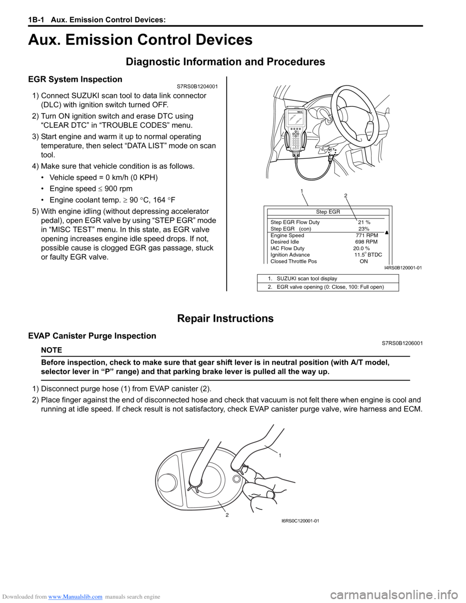
5) With engine idling (without depressing accelerator pedal), open EGR valve by using “STEP EGR” mode
in “MISC TEST” menu. In this state, as EGR valve
opening increases engine idle speed drops. If not,
possible cause is clogged EGR gas passage, stuck
or faulty EGR valve.
Repair Instructions
EVAP Canister Purge InspectionS7RS0B1206001
NOTE
Before inspection, check to make sure that gear shift lever is in neutral position (with A/T model,
selector lever in “P” range) and that parking brake lever is pulled all the way up.
1) Disconnect purge hose (1) from EVAP canister (2).
2) Place finger against the end of disconne cted hose and check that vacuum is not felt there when engine is cool and
running at idle speed. If check result is not satisfacto ry, check EVAP canister purge valve, wire harness and ECM.
1. SUZUKI scan tool display
2. EGR valve opening (0: Close, 100: Full open)
Step EGR
Step EGR Flow Duty 21 %
Step EGR (con) 23%
Engine Speed 771 RPM
Desired Idle 698 RPM
IAC Flow Duty 20.0 %
Ignition Advance 11.5 BTDC
Closed Throttle Pos ON
1 2
I4RS0B120001-01
1
2
I6RS0C120001-01
Page 269 of 1496
Downloaded from www.Manualslib.com manuals search engine Aux. Emission Control Devices: 1B-2
EVAP Canister Purge Valve and Its Circuit
Inspection
S7RS0B1206002
WARNING!
Do not apply vacuum by mouth; otherwise
harmful fuel vapor can be breathed in.
CAUTION!
Do not apply vacuum more than –86 kPa (–
12.47 psi); otherwise EVAP canister purge
valve could be damaged.
1) Prepare to operate EVAP canister purge valve as follows.
a) When using SUZUKI scan tool:
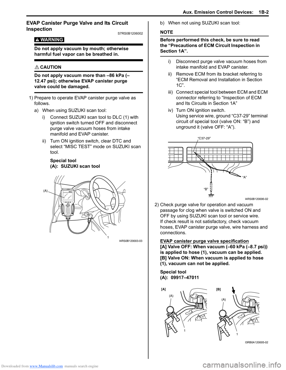
i) Connect SUZUKI scan tool to DLC (1) with ignition switch turned OFF and disconnect
purge valve vacuum hoses from intake
manifold and EVAP canister.
ii) Turn ON ignition switch, clear DTC and select “MISC TEST” mode on SUZUKI scan
tool.
Special tool
(A): SUZUKI scan tool b) When not using SUZUKI scan tool:
NOTE
Before performed this check, be sure to read
the “Precautions of ECM Circuit Inspection in
Section 1A”.
i) Disconnect purge valve vacuum hoses from
intake manifold and EVAP canister.
ii) Remove ECM from it s bracket referring to
“ECM Removal and Inst allation in Section
1C”.
iii) Connect special tool between ECM and ECM connector referring to “Inspection of ECM
and Its Circuits in Section 1A”
iv) Turn ON ignition switch. Using service wire, ground “C37-29” terminal
circuit of special tool (valve ON: “B”) and
unground it (valve OFF: “A”).
2) Check purge valve for operation and vacuum passage for clog when valve is switched ON and
OFF by using SUZUKI scan tool or service wire.
If check result is not satisfactory, check vacuum
hoses, EVAP canister purge valve, wire harness and
connections.
EVAP canister purge valve specification
[A] Valve OFF: When vacuum (–60 kPa (–8.7 psi))
is applied to hose (1), vacuum can be applied.
[B] Valve ON: When vacuum is applied to hose
(1), vacuum can not be applied.
Special tool
(A): 09917–47011
(A)
1
I4RS0B120003-03
“C37-29”“A”
“B”
I4RS0B120006-02
[A] [B]
1
(A)1
(A)
I3RB0A120005-02
Page 272 of 1496
Downloaded from www.Manualslib.com manuals search engine 1B-5 Aux. Emission Control Devices:
PCV Valve InspectionS7RS0B1206010
NOTE
Be sure to check that there is no obstruction
in PCV valve or its hoses before checking
IAC duty, for obstructed PCV valve or hose
hampers its accurate adjustment.
1) Detach air cleaner assembly.
2) Disconnect PCV valve from cylinder head cover and install plug to head cover hole.
3) Install air cleaner assembly temporarily.
4) Run engine at idle.
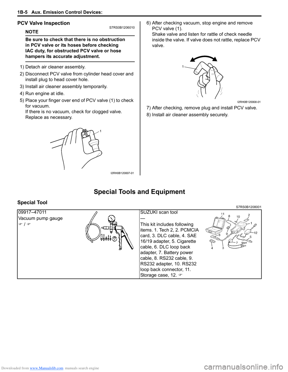
5) Place your finger over end of PCV valve (1) to check for vacuum.
If there is no vacuum, ch eck for clogged valve.
Replace as necessary. 6) After checking vacuum, stop engine and remove
PCV valve (1).
Shake valve and listen for rattle of check needle
inside the valve. If valve does not rattle, replace PCV
valve.
7) After checking, remove plug and install PCV valve.
8) Install air cleaner assembly securely.
Special Tools and Equipment
Special ToolS7RS0B1208001
I2RH0B120007-01
I2RH0B120008-01
09917–47011 SUZUKI scan tool
Vacuum pump gauge —
�) / �) This kit includes following
items. 1. Tech 2, 2. PCMCIA
card, 3. DLC cable, 4. SAE
16/19 adapter, 5. Cigarette
cable, 6. DLC loop back
adapter, 7. Battery power
cable, 8. RS232 cable, 9.
RS232 adapter, 10. RS232
loop back connector, 11.
Storage case, 12. �)
Page 284 of 1496
Downloaded from www.Manualslib.com manuals search engine 1C-12 Engine Electrical Devices:
MAF and IAT Sensor InspectionS7RS0B1306020
CAUTION!
Do not heat up MAF and IAT sensor more
than 100 °C (212 °F). Otherwise, MAF and IAT
sensor will be damaged.
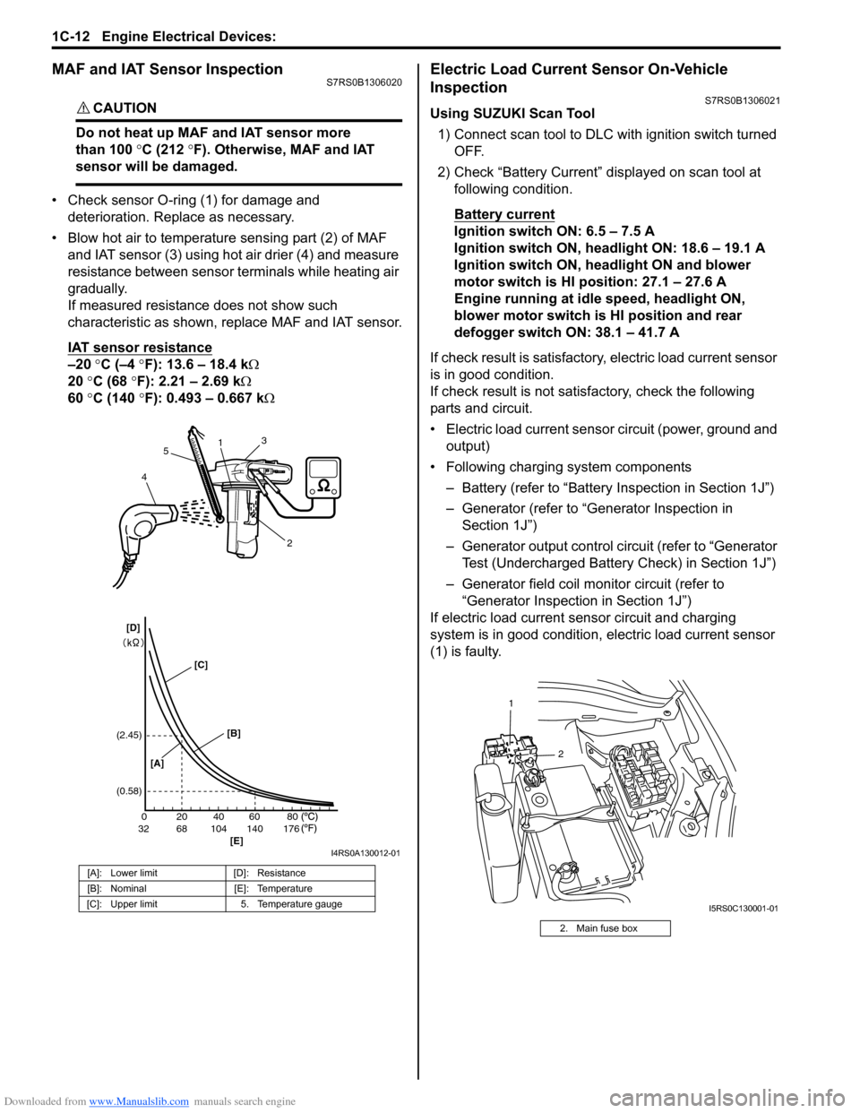
• Check sensor O-ring (1) for damage and deterioration. Replace as necessary.
• Blow hot air to temperature sensing part (2) of MAF and IAT sensor (3) using hot air drier (4) and measure
resistance between sensor terminals while heating air
gradually.
If measured resistance does not show such
characteristic as shown, replace MAF and IAT sensor.
IAT sensor resistance
–20 °C (–4 °F): 13.6 – 18.4 k Ω
20 °C (68 °F): 2.21 – 2.69 k Ω
60 °C (140 °F): 0.493 – 0.667 k Ω
Electric Load Current Sensor On-Vehicle
Inspection
S7RS0B1306021
Using SUZUKI Scan Tool
1) Connect scan tool to DLC with ignition switch turned OFF.
2) Check “Battery Current” displayed on scan tool at following condition.
Battery current
Ignition switch ON: 6.5 – 7.5 A
Ignition switch ON, headlight ON: 18.6 – 19.1 A
Ignition switch ON, headlight ON and blower
motor switch is HI position: 27.1 – 27.6 A
Engine running at idle speed, headlight ON,
blower motor switch is HI position and rear
defogger switch ON: 38.1 – 41.7 A
If check result is satisfactory, electric load current sensor
is in good condition.
If check result is not satisf actory, check the following
parts and circuit.
• Electric load current sensor circuit (power, ground and output)
• Following charging system components
– Battery (refer to “Battery Inspection in Section 1J”)
– Generator (refer to “Generator Inspection in Section 1J”)
– Generator output control ci rcuit (refer to “Generator
Test (Undercharged Battery Check) in Section 1J”)
– Generator field coil monitor circuit (refer to “Generator Inspection in Section 1J”)
If electric load current sensor circuit and charging
system is in good condition, electric load current sensor
(1) is faulty.
[A]: Lower limit [D]: Resistance
[B]: Nominal [E]: Temperature
[C]: Upper limit 5. Temperature gauge
200
6832104 140 17640 60 80
(2.45)
(0.58)
1
2
3
4 5
[A] [B]
[E]
[C]
[D]
I4RS0A130012-01
2. Main fuse box
2
1
I5RS0C130001-01
Page 285 of 1496
Downloaded from www.Manualslib.com manuals search engine Engine Electrical Devices: 1C-13
Without Using SUZUKI Scan Tool1) Measure sensor voltage between “C37-23” terminal of ECM connector and vehicle body ground referring
to “Inspection of ECM and Its Circuits in Section 1A”.
If check result is satisfactory, electric load current
sensor is in good condition.
If check result is not satisfactory, check the following
parts and circuit.
• Electric load current sensor circuit (power, ground and output)
• Following charging system components – Battery (refer to “Battery Inspection in Section
1J”)
– Generator (refer to “Generator Inspection in Section 1J”)
– Generator output control circuit (refer to “Generator Test (Undercharged Battery Check)
in Section 1J”)
– Generator field coil monitor circuit (refer to “Generator Inspection in Section 1J”) If electric load current sensor circuit and charging
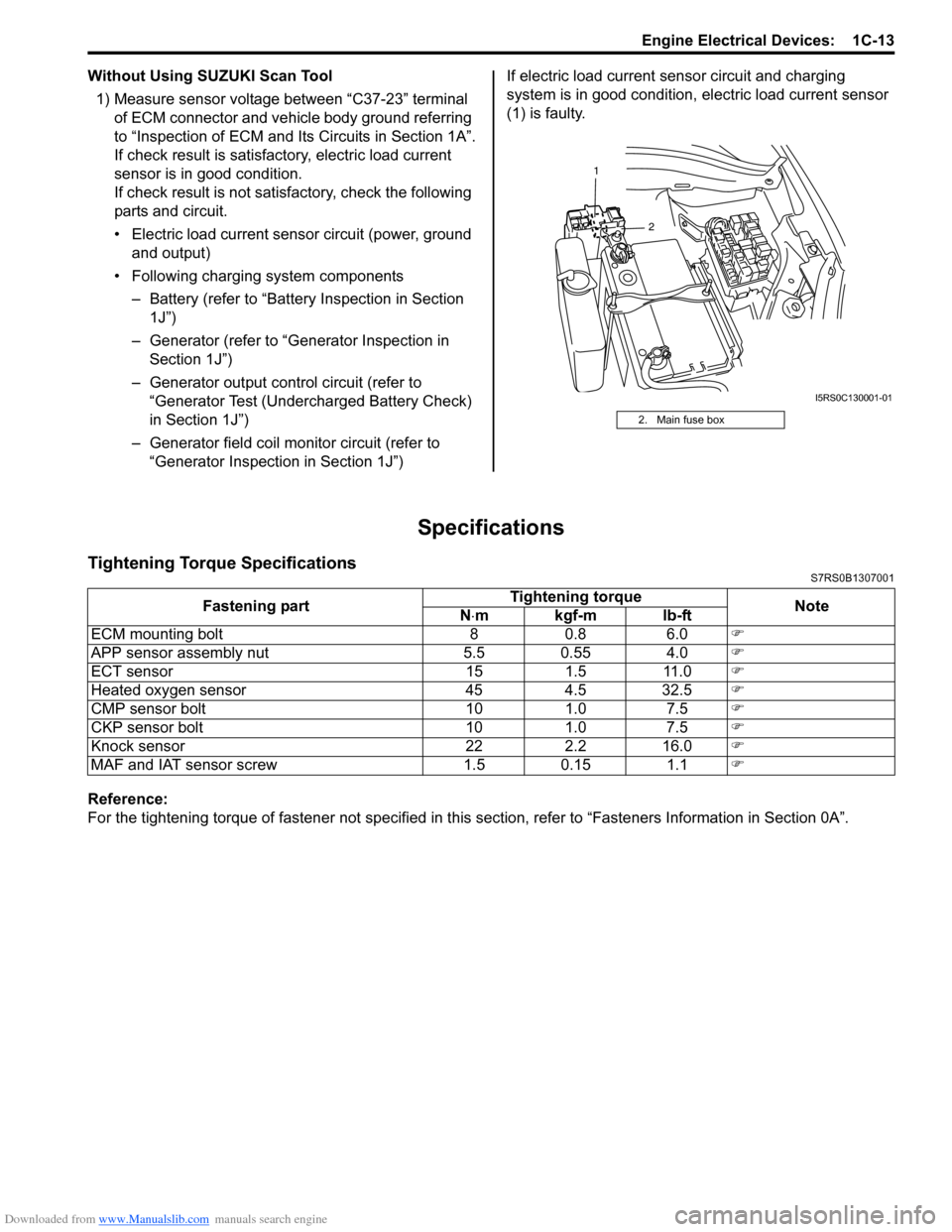
system is in good condition,
electric load current sensor
(1) is faulty.
Specifications
Tightening Torque SpecificationsS7RS0B1307001
Reference:
For the tightening torque of fastener not specified in this section, refer to “Fasteners Information in Section 0A”.
2. Main fuse box
2
1
I5RS0C130001-01
Fastening part
Tightening torque
Note
N ⋅mkgf-mlb-ft
ECM mounting bolt 8 0.8 6.0 �)
APP sensor assembly nut 5.5 0.55 4.0 �)
ECT sensor 15 1.5 11.0 �)
Heated oxygen sensor 45 4.5 32.5 �)
CMP sensor bolt 10 1.0 7.5 �)
CKP sensor bolt 10 1.0 7.5 �)
Knock sensor 22 2.2 16.0 �)
MAF and IAT sensor screw 1.5 0.15 1.1 �)
Page 385 of 1496
Downloaded from www.Manualslib.com manuals search engine Fuel System: 1G-10
4) Install suitable vinyl tube onto injector nozzle to
prevent fuel from splashing out when injecting.
5) Put graduated cylinder under injector.
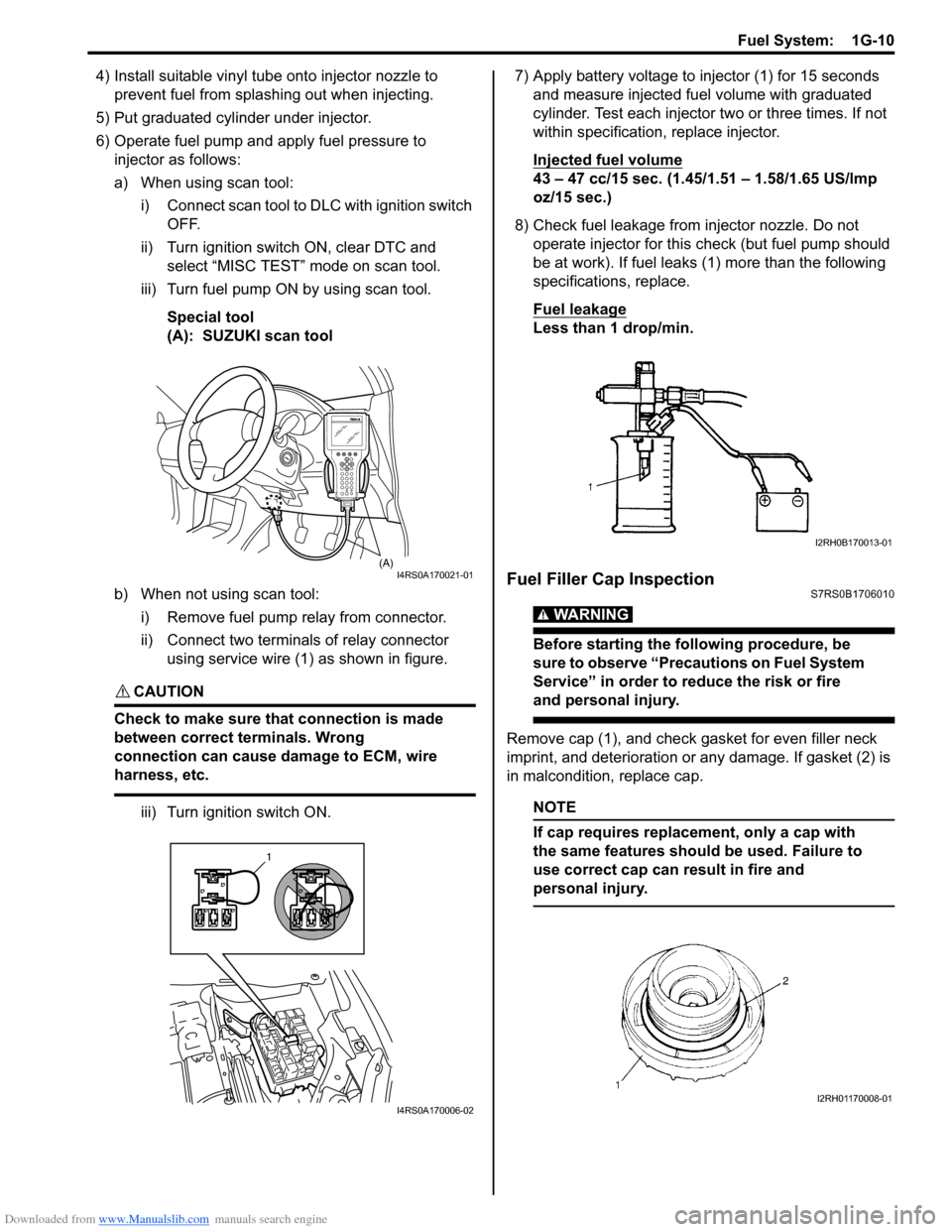
6) Operate fuel pump and apply fuel pressure to
injector as follows:
a) When using scan tool:
i) Connect scan tool to DLC with ignition switch OFF.
ii) Turn ignition switch ON, clear DTC and select “MISC TEST” mode on scan tool.
iii) Turn fuel pump ON by using scan tool.
Special tool
(A): SUZUKI scan tool
b) When not using scan tool: i) Remove fuel pump relay from connector.
ii) Connect two terminals of relay connector using service wire (1) as shown in figure.
CAUTION!
Check to make sure that connection is made
between correct terminals. Wrong
connection can cause damage to ECM, wire
harness, etc.
iii) Turn ignition switch ON. 7) Apply battery voltage to in
jector (1) for 15 seconds
and measure injected fuel volume with graduated
cylinder. Test each injector two or three times. If not
within specification, replace injector.
Injected fuel volume
43 – 47 cc/15 sec. (1.45/1.51 – 1.58/1.65 US/lmp
oz/15 sec.)
8) Check fuel leakage from injector nozzle. Do not operate injector for this check (but fuel pump should
be at work). If fuel leaks (1) more than the following
specifications, replace.
Fuel leakage
Less than 1 drop/min.
Fuel Filler Cap InspectionS7RS0B1706010
WARNING!
Before starting the following procedure, be
sure to observe “Precautions on Fuel System
Service” in order to reduce the risk or fire
and personal injury.
Remove cap (1), and che ck gasket for even filler neck
imprint, and deterioration or any damage. If gasket (2) is
in malcondition, replace cap.
NOTE
If cap requires replacement, only a cap with
the same features should be used. Failure to
use correct cap can result in fire and
personal injury.
(A)I4RS0A170021-01
1
I4RS0A170006-02
I2RH0B170013-01
I2RH01170008-01
Page 392 of 1496
Downloaded from www.Manualslib.com manuals search engine 1G-17 Fuel System:
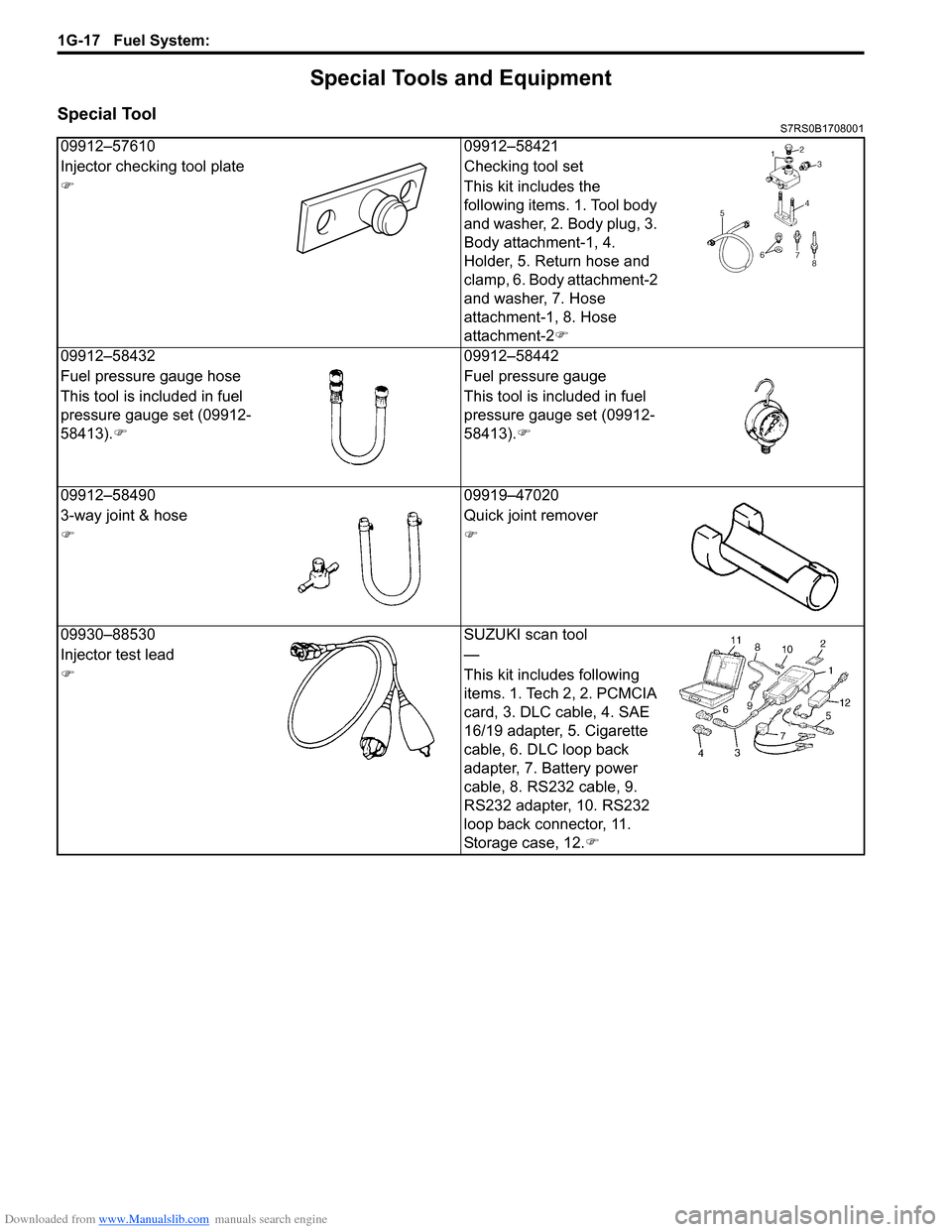
Special Tools and Equipment
Special ToolS7RS0B1708001
09912–5761009912–58421
Injector checking tool plate Checking tool set
�) This kit includes the
following items. 1. Tool body
and washer, 2. Body plug, 3.
Body attachment-1, 4.
Holder, 5. Return hose and
clamp, 6. Body attachment-2
and washer, 7. Hose
attachment-1, 8. Hose
attachment-2�)
09912–58432 09912–58442
Fuel pressure gauge hose Fuel pressure gauge
This tool is included in fuel
pressure gauge set (09912-
58413). �) This tool is included in fuel
pressure gauge set (09912-
58413).
�)
09912–58490 09919–47020
3-way joint & hose Quick joint remover
�)�)
09930–88530 SUZUKI scan tool
Injector test lead —
�) This kit includes following
items. 1. Tech 2, 2. PCMCIA
card, 3. DLC cable, 4. SAE
16/19 adapter, 5. Cigarette
cable, 6. DLC loop back
adapter, 7. Battery power
cable, 8. RS232 cable, 9.
RS232 adapter, 10. RS232
loop back connector, 11.
Storage case, 12.�)
Page 400 of 1496

Downloaded from www.Manualslib.com manuals search engine 1H-8 Ignition System:
Ignition Coil Assembly (Including ignitor)
Removal and Installation
S7RS0B1806005
Removal1) Disconnect negative (–) cable at battery.
2) Remove air cleaner assembly with air intake pipe and cylinder head upper cover.
3) Disconnect ignition coil coupler.
4) Disconnect high-tension cord (3) from ignition coil assembly (2).
5) Remove ignition coil bolts (1) and then pull out ignition coil assembly.
Installation 1) Install ignition coil assembly (2).
2) Tighten ignition coil bolts (1) to specified torque, and then connect igni tion coil coupler.
Tightening torque
Ignition coil bolt (a): 10 N·m (1.0 kgf-m, 7.5 lb-ft)
3) Install high-tension cord (3) to ignition coil assembly while gripping its cap.
4) Install cylinder head upper cover and air cleaner assembly with air intake pipe.
5) Connect negative (–) cable to battery.
Ignition Coil Assembly (Including ignitor)
Inspection
S7RS0B1806006
Measure secondary coil for resistance.
If resistance is out of specification, replace ignition coil
assembly.
Secondary coil resistance
7.5 – 10.3 k Ω at 20 °C, 68 ° F
Ignition Timing InspectionS7RS0B1806007
NOTE
• Ignition timing is not adjustable. If ignition
timing is out of specification, check
system related parts.
• Before starting engine, place transmission gear shift lever in “Neutral” (shift selector
lever to “P” range for A/T model), and set
parking brake.
1) Connect scan tool to DLC (1) with ignition switch OFF.
Special tool
(A): SUZUKI scan tool
2) Start engine and warm it up to normal operating temperature.
3) Make sure that all of electrical loads except ignition are switched off.
4) Check to be sure that idle speed is within specification referring to “Idle Speed and IAC
Throttle Valve Opening Inspection in Section 1A”
5) Fix ignition timing by using “Fixed Spark” of “Misc Test” mode on scan tool.
I2RH0B180006-01
I3RM0A180004-01
I2RH0B180007-01
(A)
1
I4RS0B180003-01