exhaust SUZUKI SWIFT 2006 2.G Service User Guide
[x] Cancel search | Manufacturer: SUZUKI, Model Year: 2006, Model line: SWIFT, Model: SUZUKI SWIFT 2006 2.GPages: 1496, PDF Size: 34.44 MB
Page 49 of 1496
Downloaded from www.Manualslib.com manuals search engine Table of Contents 1-v
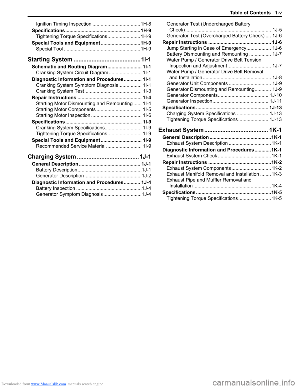
Ignition Timing Inspection ................................... 1H-8
Specifications ....................................................... 1H-9
Tightening Torque Specifications ........................ 1H-9
Special Tools and Equipmen t ............................. 1H-9
Special Tool ........................................................ 1H-9
Starting System ................. ........................ 1I-1
Schematic and Routing Diagram ......................... 1I-1
Cranking System Circuit Diagram ........................ 1I-1
Diagnostic Information and Procedures ............. 1I-1
Cranking System Symptom Diagnosis ................. 1I-1
Cranking System Test.......................................... 1I-3
Repair Instructions ............................................... 1I-4 Starting Motor Dismounting and Remounting ...... 1I-4
Starting Motor Components ................................. 1I-5
Starting Motor Inspection ..................................... 1I-6
Specifications ........................................................ 1I-9
Cranking System Specifications........................... 1I-9
Tightening Torque Specifications ......................... 1I-9
Special Tools and Equipment .............................. 1I-9
Recommended Service Material .......................... 1I-9
Charging System ............ .......................... 1J-1
General Description ......... .................................... 1J-1
Battery Description ...............................................1J-1
Generator Descripti on ..........................................1J-2
Diagnostic Information and Procedures ............ 1J-4 Battery Inspection ................................................1J-4
Generator Symptom Diagnosis ............................1J-4 Generator Test (Undercharged Battery
Check) ............................................................... 1J-5
Generator Test (Overcharg ed Battery Check) .... 1J-6
Repair Instructions ........... ................................... 1J-6
Jump Starting in Case of Emergency.................. 1J-6
Battery Dismounting and Remounting ................ 1J-7
Water Pump / Generator Drive Belt Tension Inspection and Adjustment ................................ 1J-7
Water Pump / Generator Drive Belt Removal and Installation .................................................. 1J-8
Generator Unit Co mponents ............................... 1J-9
Generator Dismounting a nd Remounting............ 1J-9
Generator Components........ ............................. 1J-10
Generator Insp ection......................................... 1J-11
Specifications ..................................................... 1J-13 Charging System Specifications ....................... 1J-13
Tightening Torque Specifications ...................... 1J-13
Exhaust System .............. ......................... 1K-1
General Description .............................................1K-1
Exhaust System Description ............................... 1K-1
Diagnostic Information and Procedures ............1K-1 Exhaust System Check ....................................... 1K-1
Repair Instructions ........... ...................................1K-2
Exhaust System Components ............................. 1K-2
Exhaust Manifold Removal and Installation ........ 1K-3
Exhaust Pipe and Muffler Removal and Installation ......................................................... 1K-4
Specifications .................... ...................................1K-5
Tightening Torque Specifications ........................ 1K-5
Page 53 of 1496
Downloaded from www.Manualslib.com manuals search engine Engine General Information and Diagnosis: 1A-3
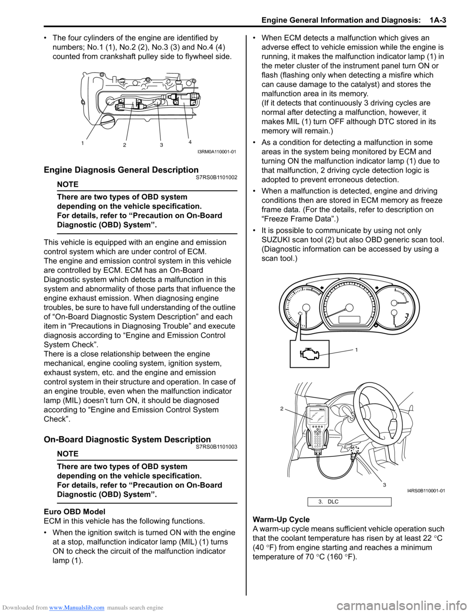
• The four cylinders of the engine are identified by numbers; No.1 (1), No.2 (2 ), No.3 (3) and No.4 (4)
counted from crankshaft pulley side to flywheel side.
Engine Diagnosis General DescriptionS7RS0B1101002
NOTE
There are two types of OBD system
depending on the vehicle specification.
For details, refer to “Precaution on On-Board
Diagnostic (OBD) System”.
This vehicle is equipped with an engine and emission
control system which are under control of ECM.
The engine and emission control system in this vehicle
are controlled by ECM. ECM has an On-Board
Diagnostic system which detects a malfunction in this
system and abnormality of those parts that influence the
engine exhaust emission. When diagnosing engine
troubles, be sure to have full understanding of the outline
of “On-Board Diagnostic System Description” and each
item in “Precautions in Diagnosing Trouble” and execute
diagnosis according to “Engine and Emission Control
System Check”.
There is a close relationship between the engine
mechanical, engine cooling system, ignition system,
exhaust system, etc. and the engine and emission
control system in their structure and operation. In case of
an engine trouble, even when the malfunction indicator
lamp (MIL) doesn’t turn ON, it should be diagnosed
according to “Engine and Emission Control System
Check”.
On-Board Diagnostic System DescriptionS7RS0B1101003
NOTE
There are two types of OBD system
depending on the vehicle specification.
For details, refer to “Precaution on On-Board
Diagnostic (OBD) System”.
Euro OBD Model
ECM in this vehicle has the following functions.
• When the ignition switch is turned ON with the engine at a stop, malfunction indicator lamp (MIL) (1) turns
ON to check the circuit of the malfunction indicator
lamp (1). • When ECM detects a malfunction which gives an
adverse effect to vehicle emission while the engine is
running, it makes the malfunction indicator lamp (1) in
the meter cluster of the inst rument panel turn ON or
flash (flashing only when detecting a misfire which
can cause damage to the catalyst) and stores the
malfunction area in its memory.
(If it detects that contin uously 3 driving cycles are
normal after detecting a malfunction, however, it
makes MIL (1) turn OFF although DTC stored in its
memory will remain.)
• As a condition for detecting a malfunction in some areas in the system being monitored by ECM and
turning ON the malfunction indicator lamp (1) due to
that malfunction, 2 driving cycle detection logic is
adopted to prevent erroneous detection.
• When a malfunction is detected, engine and driving conditions then are stored in ECM memory as freeze
frame data. (For the details, refer to description on
“Freeze Frame Data”.)
• It is possible to communicate by using not only SUZUKI scan tool (2) but also OBD generic scan tool.
(Diagnostic information can be accessed by using a
scan tool.)
Warm-Up Cycle
A warm-up cycle means sufficie nt vehicle operation such
that the coolant temperature has risen by at least 22 °C
(40 °F) from engine starting and reaches a minimum
temperature of 70 °C (160 ° F).
1
23 4
I3RM0A110001-01
3. DLC
2
3
1
I4RS0B110001-01
Page 63 of 1496
Downloaded from www.Manualslib.com manuals search engine Engine General Information and Diagnosis: 1A-13
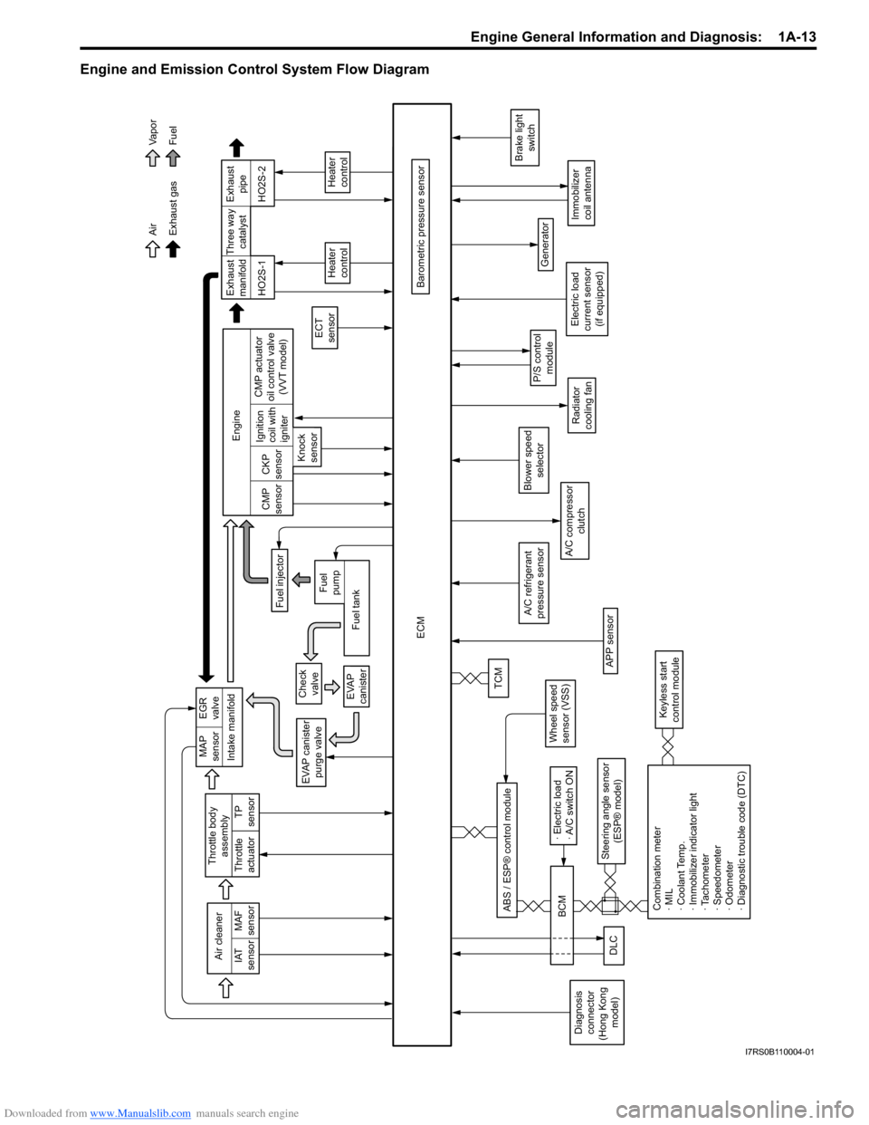
Engine and Emission Control System Flow Diagram
Intake manifold
Exhaust gas AirFuel
Va p o r
EVAP canister purge valve
ECM
Barometric pressure sensor
A/C compressor clutch
Generator
Immobilizer
coil antenna
P/S controlmodule
Brake light switch
Air cleaner
IAT
sensor MAF
sensor
A/C refrigerant
pressure sensor
TP
sensor
Throttle body
assembly
Throttle
actuator
Wheel speed
sensor (VSS)
Steering angle sensor (ESP® model)
ABS / ESP® control module
Blower speed
selector
MAP
sensor EGR
valve
Check valve
EVAP
canisterTCM
Exhaust
manifold Exhaust
pipe
Fuel injector
ECT
sensor
Heater
control
HO2S-1 HO2S-2
Engine
CMP
sensor CKP
sensor
Knock
sensor Ignition
coil with
igniter
Fuel tank
Fuel
pump CMP actuator
oil control valve (VVT model) Three way
catalyst
Heater
control
Radiator
cooling fan
Combination meter
· MIL
· Coolant Temp.
· Immobilizer indicator light
· Tachometer
· Speedometer
· Odometer
· Diagnostic trouble code (DTC)
Keyless start
control module
DLC
· Electric load
· A/C switch ON
BCM
Diagnosis
connector
(Hong Kong model) Electric load
current sensor (if equipped)
APP sensor
I7RS0B110004-01
Page 79 of 1496
Downloaded from www.Manualslib.com manuals search engine Engine General Information and Diagnosis: 1A-29
�) *P0140 O2 sensor (HO2S) circuit no
activity detected (Sensor-2) Output voltage of HO2S-2 is more than specification after
warming up engine. 2 driving
cycles
�)
�{ *P0171 System too lean Total fuel trim is larger than
specification for specified time
or longer. (Fuel trim towa rd rich side is large.) 2 driving
cycles
�)
�{ *P0172 System too rich Total fuel trim is smaller th
an specification for specified
time or longer. (Fue l trim toward lean side is large.) 2 driving
cycles
�) *P0222 Throttle/pedal position sensor
(sub)/switch “B” circuit low Output voltage of TP sensor (sub) is lower than
specification 1 driving
cycle
�) *P0223 Throttle/pedal position sensor
(sub)/switch “B” circuit high Output voltage of TP sensor (sub) is higher than
specification 1 driving
cycle
�)
�U *P0300 Random/multiple cylinder
misfire detected Misfire of such level as to cause damage to three way
catalyst. *2 driving
cycles
�)
�U *P0301 /
�U *P0302 /
�U *P0303 /
�U *P0304 Cylinder 1 misfire detected
Cylinder 2 misfire detected
Cylinder 3 misfire detected
Cylinder 4 misfire detected
Misfire of such level as to deteriorate emission but not to
cause damage to three way catalyst.
*2 driving
cycles
�) *P0327 Knock sensor 1 circuit low Output voltage of knock sensor is less than specification.1 driving
cycle
�) *P0328 Knock sensor 1 circuit high Output volta ge of knock sensor is more than specification.1 driving
cycle
�) *P0335 Crankshaft position sensor “A”
circuit No signal of CKP sensor for sp
ecified time even if starting
motor signal is input. 1 driving
cycle
�) *P0340 Camshaft position sensor “A”
circuit CMP sensor pulse is out of specification. 1 driving
cycle
�) �† P0350 Ignition c
oil primary /
secondary circuit Ignition signal is not inputted to monitor circuit 5 times or
more continuously. 1 driving
cycle
�)
�{ *P0401 Exhaust gas recirculation flow
insufficient detected Difference in intake manifold absolute pressure between
opened EGR valve and closed EGR valve is less than
specification. 2 driving
cycles
�)
�{ *P0402 Exhaust gas recirculation flow
excessive detected Difference in intake manifold absolute pressure between
opened EGR valve and closed EGR valve is more than
specification. 2 driving
cycles
�) *P0403 Exhaust gas recirculation
control circuit Output voltage is different from output command with
more than one pole out of 4 poles. 1 driving
cycle
�)
�U *P0420 Catalyst system efficiency
below threshold
Output waveforms of HO2S-1 and HO2S-2 are similar. 2 driving
cycles
�) *P0443 Evaporative emission system
purge control valve circuit Monitor signal of EVAP canister purge valve is different
from command signal. (circuit open or shorted to ground) 2 driving
cycles
�) *P0480 Fan 1 (Radiator cooling fan)
control circuit Monitor signal of radiator cooling fan relay is different from
command signal. 1 driving
cycle
�) *P0500 Vehicle speed sensor “A” No VSS signal during fuel cut fo
r specified time or longer,
or VSS signal is not input even if vehicle is driving with
more than specified engine speed and D-range (for A/T
model). 2 driving
cycles
�) P0532 A/C refrigerant pressure sensor
“A” circuit low Output voltage of A/C refrigerant pressure sensor is less
than specification.
—
�) P0533 A/C refrigerant pressure sensor
“A” circuit high Output voltage of A/C refrigerant pressure sensor is more
than specification.
—
�) *P0601 Internal control module
memory check sum error Data write error or check sum error. 1 driving
cycle
�) P0602 Control module programming
error Data programming error.
—
�) *P0607 Control module performance Data programming error. 1 driving
cycle
�)
�U *P061
6Starter relay circuit low Starter signal is low voltage even though engine is started
with vehicle at stop. 2 driving
cycles
DTC No. Detecting item
Detecting condition
(DTC will set when detecting:) MIL
Page 85 of 1496
Downloaded from www.Manualslib.com manuals search engine Engine General Information and Diagnosis: 1A-35
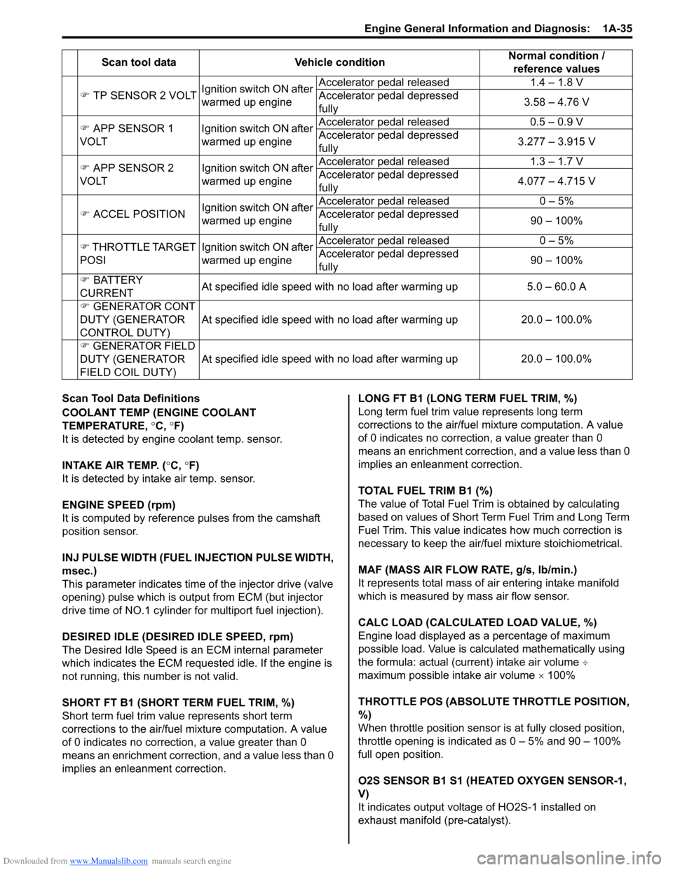
Scan Tool Data Definitions
COOLANT TEMP (ENGINE COOLANT
TEMPERATURE, °C, °F)
It is detected by engine coolant temp. sensor.
INTAKE AIR TEMP. ( °C, °F)
It is detected by intake air temp. sensor.
ENGINE SPEED (rpm)
It is computed by reference pulses from the camshaft
position sensor.
INJ PULSE WIDTH (FUEL INJECTION PULSE WIDTH,
msec.)
This parameter indicates time of the injector drive (valve
opening) pulse which is output from ECM (but injector
drive time of NO.1 cylinder fo r multiport fuel injection).
DESIRED IDLE (DESIRED IDLE SPEED, rpm)
The Desired Idle Speed is an ECM internal parameter
which indicates the ECM requested idle. If the engine is
not running, this number is not valid.
SHORT FT B1 (SHORT TERM FUEL TRIM, %)
Short term fuel trim valu e represents short term
corrections to the air/fuel mixture computation. A value
of 0 indicates no correction, a value greater than 0
means an enrichment correction, and a value less than 0
implies an enleanment correction. LONG FT B1 (LONG TERM FUEL TRIM, %)
Long term fuel trim value represents long term
corrections to the air/fuel mixture computation. A value
of 0 indicates no correction, a value greater than 0
means an enrichment correction, and a value less than 0
implies an enleanment correction.
TOTAL FUEL TRIM B1 (%)
The value of Total Fuel Trim is obtained by calculating
based on values of Short Term Fuel Trim and Long Term
Fuel Trim. This value indica
tes how much correction is
necessary to keep the air/fuel mixture stoichiometrical.
MAF (MASS AIR FLOW RATE, g/s, lb/min.)
It represents total mass of air entering intake manifold
which is measured by mass air flow sensor.
CALC LOAD (CALCULATED LOAD VALUE, %)
Engine load displayed as a percentage of maximum
possible load. Value is calculated mathematically using
the formula: actual (current) intake air volume ÷
maximum possible intake air volume × 100%
THROTTLE POS (ABSOLUTE THROTTLE POSITION,
%)
When throttle position sensor is at fully closed position,
throttle opening is indicated as 0 – 5% and 90 – 100%
full open position.
O2S SENSOR B1 S1 (HEA TED OXYGEN SENSOR-1,
V)
It indicates output voltage of HO2S-1 installed on
exhaust manifold (pre-catalyst).
�)
TP SENSOR 2 VOLT Ignition switch ON after
warmed up engine Accelerator pedal released
1.4 – 1.8 V
Accelerator pedal depressed
fully 3.58 – 4.76 V
�) APP SENSOR 1
VOLT Ignition switch ON after
warmed up engineAccelerator pedal released
0.5 – 0.9 V
Accelerator pedal depressed
fully 3.277 – 3.915 V
�) APP SENSOR 2
VOLT Ignition switch ON after
warmed up engineAccelerator pedal released
1.3 – 1.7 V
Accelerator pedal depressed
fully 4.077 – 4.715 V
�) ACCEL POSITION Ignition switch ON after
warmed up engine Accelerator pedal released
0 – 5%
Accelerator pedal depressed
fully 90 – 100%
�) THROTTLE TARGET
POSI Ignition switch ON after
warmed up engineAccelerator pedal released
0 – 5%
Accelerator pedal depressed
fully 90 – 100%
�) BATTERY
CURRENT At specified idle speed with no load after warming up
5.0 – 60.0 A
�) GENERATOR CONT
DUTY (GENERATOR
CONTROL DUTY) At specified idle speed with no load after warming up
20.0 – 100.0%
�) GENERATOR FIELD
DUTY (GENERATOR
FIELD COIL DUTY) At spe
cified idle speed with no load after warming up
20.0 – 100.0%
Scan tool data
Vehicle condition Normal condition /
reference values
Page 86 of 1496
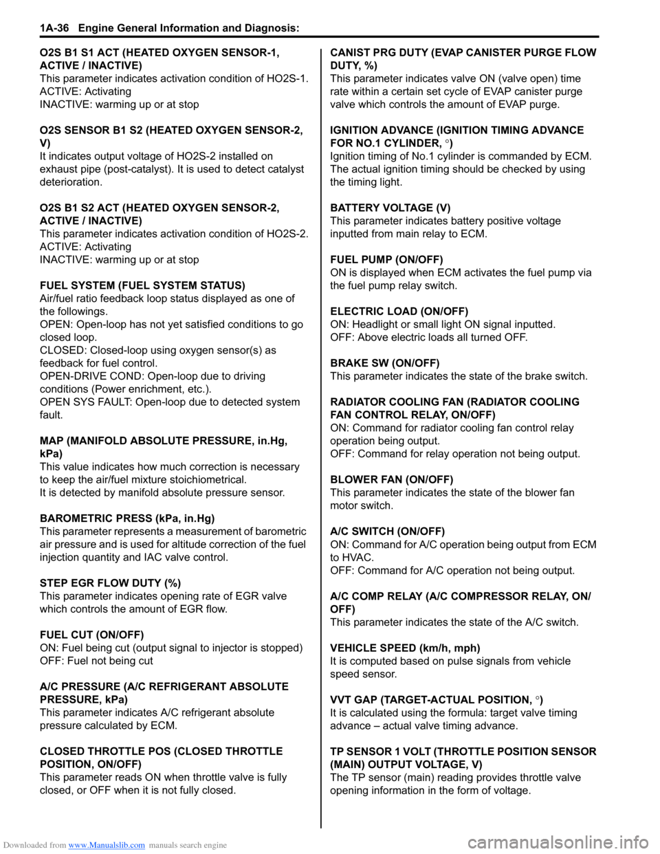
Downloaded from www.Manualslib.com manuals search engine 1A-36 Engine General Information and Diagnosis:
O2S B1 S1 ACT (HEATED OXYGEN SENSOR-1,
ACTIVE / INACTIVE)
This parameter indicates activation condition of HO2S-1.
ACTIVE: Activating
INACTIVE: warming up or at stop
O2S SENSOR B1 S2 (HEATED OXYGEN SENSOR-2,
V)
It indicates output voltage of HO2S-2 installed on
exhaust pipe (post-catalyst). It is used to detect catalyst
deterioration.
O2S B1 S2 ACT (HEATED OXYGEN SENSOR-2,
ACTIVE / INACTIVE)
This parameter indicates acti vation condition of HO2S-2.
ACTIVE: Activating
INACTIVE: warming up or at stop
FUEL SYSTEM (FUEL SYSTEM STATUS)
Air/fuel ratio feedback loop status displayed as one of
the followings.
OPEN: Open-loop has not yet satisfied conditions to go
closed loop.
CLOSED: Closed-loop using oxygen sensor(s) as
feedback for fuel control.
OPEN-DRIVE COND: Open-loop due to driving
conditions (Power enrichment, etc.).
OPEN SYS FAULT: Open-loop due to detected system
fault.
MAP (MANIFOLD ABSOLUTE PRESSURE, in.Hg,
kPa)
This value indicates how much correction is necessary
to keep the air/fuel mixture stoichiometrical.
It is detected by manifold absolute pressure sensor.
BAROMETRIC PRESS (kPa, in.Hg)
This parameter represents a measurement of barometric
air pressure and is used for al titude correction of the fuel
injection quantity and IAC valve control.
STEP EGR FLOW DUTY (%)
This parameter indicates opening rate of EGR valve
which controls the amount of EGR flow.
FUEL CUT (ON/OFF)
ON: Fuel being cut (output signal to injector is stopped)
OFF: Fuel not being cut
A/C PRESSURE (A/C REFRIGERANT ABSOLUTE
PRESSURE, kPa)
This parameter indicates A/C refrigerant absolute
pressure calculated by ECM.
CLOSED THROTTLE PO S (CLOSED THROTTLE
POSITION, ON/OFF)
This parameter reads ON wh en throttle valve is fully
closed, or OFF when it is not fully closed. CANIST PRG DUTY (EVAP CANISTER PURGE FLOW
DUTY, %)
This parameter indicates valve ON (valve open) time
rate within a certain set cycle of EVAP canister purge
valve which controls the amount of EVAP purge.
IGNITION ADVANCE (IGNITION TIMING ADVANCE
FOR NO.1 CYLINDER,
°)
Ignition timing of No.1 cylinder is commanded by ECM.
The actual ignition timing should be checked by using
the timing light.
BATTERY VOLTAGE (V)
This parameter indicates battery positive voltage
inputted from main relay to ECM.
FUEL PUMP (ON/OFF)
ON is displayed when ECM activates the fuel pump via
the fuel pump relay switch.
ELECTRIC LOAD (ON/OFF)
ON: Headlight or small light ON signal inputted.
OFF: Above electric loads all turned OFF.
BRAKE SW (ON/OFF)
This parameter indicates the state of the brake switch.
RADIATOR COOLING FAN (RADIATOR COOLING
FAN CONTROL RELAY, ON/OFF)
ON: Command for radiator cooling fan control relay
operation being output.
OFF: Command for relay operation not being output.
BLOWER FAN (ON/OFF)
This parameter indicates the state of the blower fan
motor switch.
A/C SWITCH (ON/OFF)
ON: Command for A/C operatio n being output from ECM
to HVAC.
OFF: Command for A/C oper ation not being output.
A/C COMP RELAY (A/C COMPRESSOR RELAY, ON/
OFF)
This parameter indicates the state of the A/C switch.
VEHICLE SPEED (km/h, mph)
It is computed based on pulse signals from vehicle
speed sensor.
VVT GAP (TARGET-ACTUAL POSITION, °)
It is calculated using the formula: target valve timing
advance – actual valve timing advance.
TP SENSOR 1 VOLT (THROTTLE POSITION SENSOR
(MAIN) OUTPUT VOLTAGE, V)
The TP sensor (main) reading provides throttle valve
opening information in the form of voltage.
Page 87 of 1496
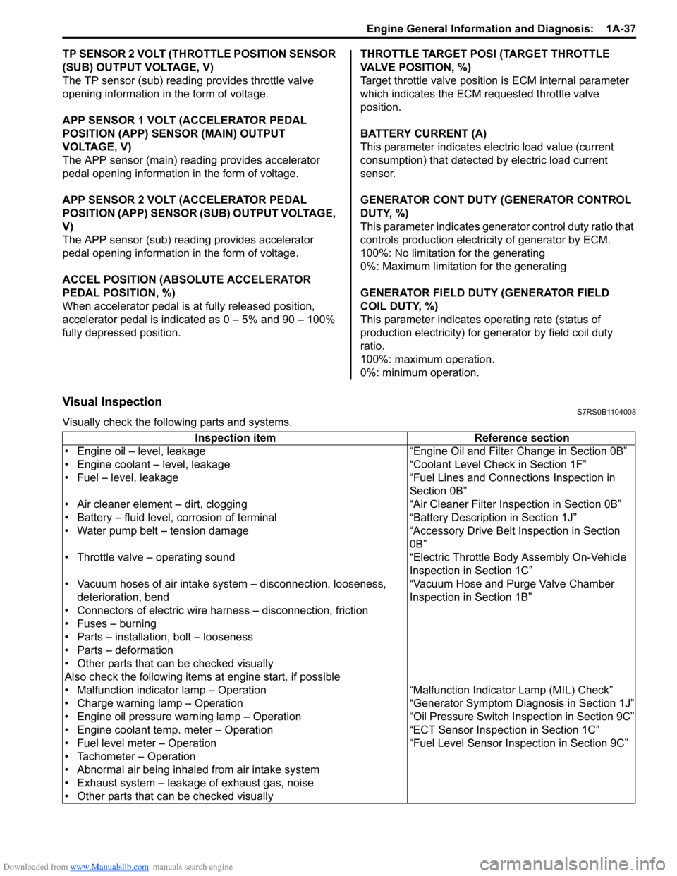
Downloaded from www.Manualslib.com manuals search engine Engine General Information and Diagnosis: 1A-37
TP SENSOR 2 VOLT (THROTTLE POSITION SENSOR
(SUB) OUTPUT VOLTAGE, V)
The TP sensor (sub) reading provides throttle valve
opening information in the form of voltage.
APP SENSOR 1 VOLT (ACCELERATOR PEDAL
POSITION (APP) SENSOR (MAIN) OUTPUT
VOLTAGE, V)
The APP sensor (main) read ing provides accelerator
pedal opening information in the form of voltage.
APP SENSOR 2 VOLT (ACCELERATOR PEDAL
POSITION (APP) SENSOR (S UB) OUTPUT VOLTAGE,
V)
The APP sensor (sub) reading provides accelerator
pedal opening information in the form of voltage.
ACCEL POSITION (ABSOLUTE ACCELERATOR
PEDAL POSITION, %)
When accelerator pedal is at fully released position,
accelerator pedal is indicated as 0 – 5% and 90 – 100%
fully depressed position. THROTTLE TARGET POSI (TARGET THROTTLE
VALVE POSITION, %)
Target throttle valve position is ECM internal parameter
which indicates the ECM requested throttle valve
position.
BATTERY CURRENT (A)
This parameter indicates elec
tric load value (current
consumption) that detected by electric load current
sensor.
GENERATOR CONT DUTY (GENERATOR CONTROL
DUTY, %)
This parameter indicates generator control duty ratio that
controls production electricity of generator by ECM.
100%: No limitation for the generating
0%: Maximum limitation for the generating
GENERATOR FIELD DUTY (GENERATOR FIELD
COIL DUTY, %)
This parameter indicates ope rating rate (status of
production electricity) for gen erator by field coil duty
ratio.
100%: maximum operation.
0%: minimum operation.
Visual InspectionS7RS0B1104008
Visually check the following parts and systems.
Inspection item Reference section
• Engine oil – level, leakage “Engine Oil and Filter Change in Section 0B”
• Engine coolant – level, leakage “Co olant Level Check in Section 1F”
• Fuel – level, leakage “Fuel Lines and Connections Inspection in Section 0B”
• Air cleaner element – dirt, clogging “Air Cleaner Filter Inspection in Section 0B”
• Battery – fluid level, corrosion of terminal “Battery Description in Section 1J”
• Water pump belt – tension damage “Accessory Drive Belt Inspection in Section 0B”
• Throttle valve – operating sound “Electric Throttle Body Assembly On-Vehicle Inspection in Section 1C”
• Vacuum hoses of air intake system – disconnection, looseness,
deterioration, bend “Vacuum Hose and Purge Valve Chamber
Inspection in Section 1B”
• Connectors of electric wire harness – disconnection, friction
• Fuses – burning
• Parts – installation, bolt – looseness
• Parts – deformation
• Other parts that can be checked visually
Also check the following items at engine start, if possible
• Malfunction indicator lamp – Operation “Malfunction Indicator Lamp (MIL) Check”
• Charge warning lamp – Operation “Genera tor Symptom Diagnosis in Section 1J”
• Engine oil pressure warning lamp – Operation “O il Pressure Switch Inspection in Section 9C”
• Engine coolant temp. meter – Operation “ECT Sensor Inspection in Section 1C”
• Fuel level meter – Operation “Fuel Level Sensor Inspection in Section 9C”
• Tachometer – Operation
• Abnormal air being inhaled from air intake system
• Exhaust system – leakage of exhaust gas, noise
• Other parts that can be checked visually
Page 138 of 1496
Downloaded from www.Manualslib.com manuals search engine 1A-88 Engine General Information and Diagnosis:
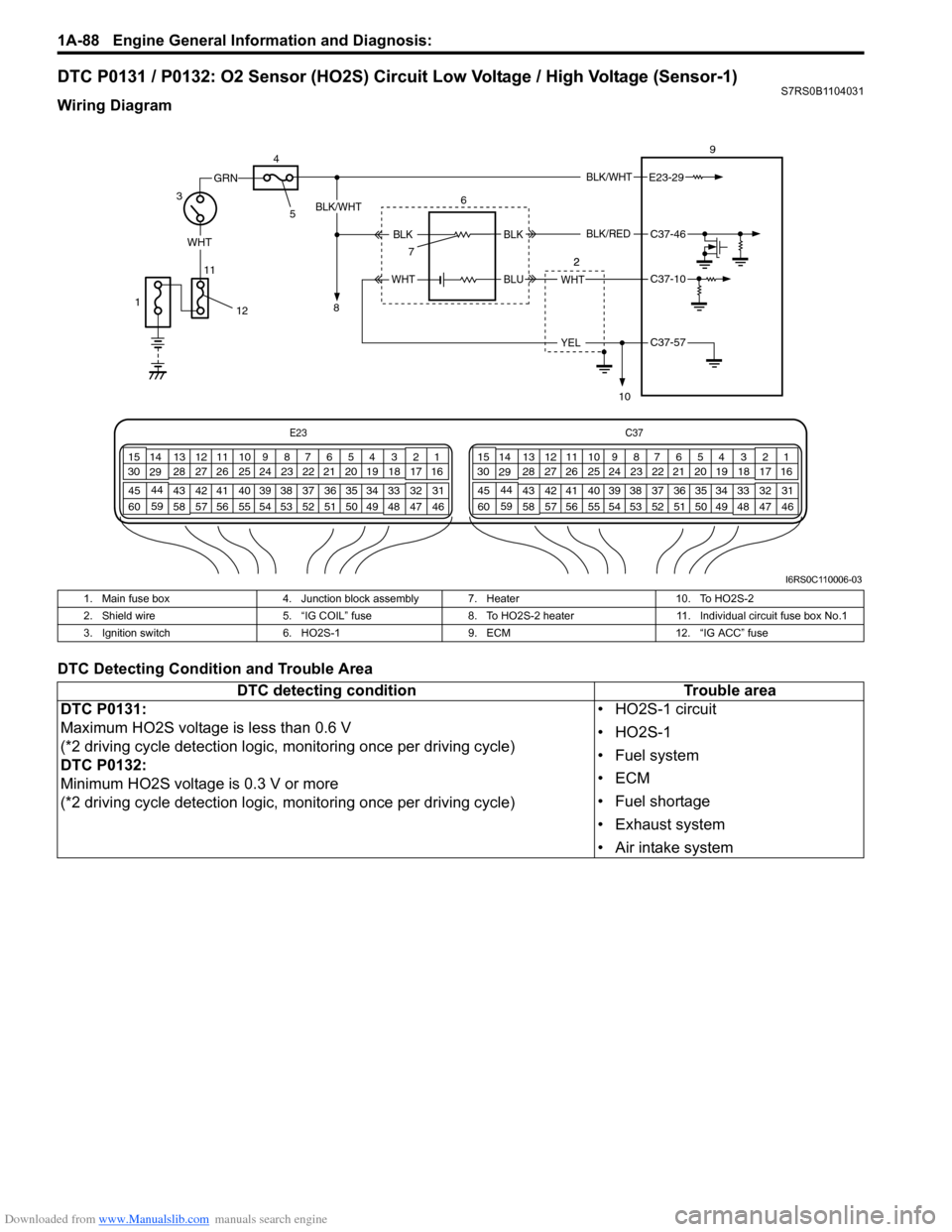
DTC P0131 / P0132: O2 Sensor (HO2S) Circuit Low Voltage / High Voltage (Sensor-1)S7RS0B1104031
Wiring Diagram
DTC Detecting Condition and Trouble Area
E23C37
34
1819
567
1011
17
20
47 46
495051
2122
52 16
25 9
24
14
29
55
57 54 53
59
60 58 2
262728
15
30
56 4832 31
34353637
40
42 39 38
44
45 43 41 331
1213
238
34
1819
567
1011
17
20
47 46
495051
2122
52 16
25 9
24
14
29
55
57 54 53
59
60 58 2
262728
15
30
56 4832 31
34353637
40
42 39 38
44
45 43 41 331
1213
238
BLK/WHT
WHT
11
GRN
3 9
E23-29
WHT
YEL
BLK/WHT
BLKC37-46
C37-10
C37-57
6
7
10
BLK
BLUWHT
BLK/RED
4
5
8
12
1
I6RS0C110006-03
1. Main fuse box
4. Junction block assembly 7. Heater 10. To HO2S-2
2. Shield wire 5. “IG COIL” fuse8. To HO2S-2 heater 11. Individual circuit fuse box No.1
3. Ignition switch 6. HO2S-19. ECM 12. “IG ACC” fuse
DTC detecting condition Trouble area
DTC P0131:
Maximum HO2S voltage is less than 0.6 V
(*2 driving cycle detection logic, monitoring once per driving cycle)
DTC P0132:
Minimum HO2S voltage is 0.3 V or more
(*2 driving cycle detection logic, monitoring once per driving cycle) • HO2S-1 circuit
•HO2S-1
• Fuel system
•ECM
• Fuel shortage
• Exhaust system
• Air intake system
Page 140 of 1496
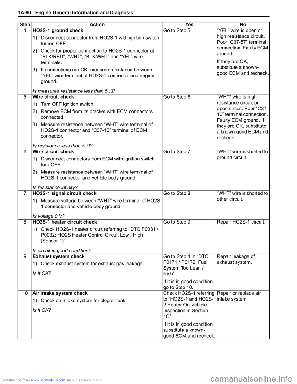
Downloaded from www.Manualslib.com manuals search engine 1A-90 Engine General Information and Diagnosis:
4HO2S-1 ground check
1) Disconnect connector from HO 2S-1 with ignition switch
turned OFF.
2) Check for proper connection to HO2S-1 connector at “BLK/RED”, “WHT”, “BLK /WHT” and “YEL” wire
terminals.
3) If connections are OK, m easure resistance between
“YEL” wire terminal of HO2S-1 connector and engine
ground.
Is measured resistance less than 5
Ω? Go to Step 5. “YEL” wire is open or
high resistance circuit.
Poor “C37-57” terminal
connection. Faulty ECM
ground.
If they are OK,
substitute a known-
good ECM and recheck.
5 Wire circuit check
1) Turn OFF ignition switch.
2) Remove ECM from its br acket with ECM connectors
connected.
3) Measure resistance between “WHT” wire terminal of HO2S-1 connector and “C37-10” terminal of ECM
connector.
Is resistance less than 5
Ω? Go to Step 6. “WHT” wire is high
resistance circuit or
open circuit. Poor “C37-
10” terminal connection.
Faulty ECM ground. If
they are OK, substitute
a known-good ECM and
recheck.
6 Wire circuit check
1) Disconnect connectors from ECM with ignition switch
turn OFF.
2) Measure resistance between “WHT” wire terminal of HO2S-1 connector and vehicle body ground.
Is resistance infinity? Go to Step 7. “WHT” wire is shorted to
ground circuit.
7 HO2S-1 signal circuit check
1) Measure voltage between “WHT” wire terminal of HO2S-
1 connector and vehicle body ground.
Is voltage 0 V? Go to Step 8. “WHT” wire is shorted to
other circuit.
8 HO2S-1 heater circuit check
1) Check HO2S-1 heater circuit referring to “DTC P0031 /
P0032: HO2S Heater Control Circuit Low / High
(Sensor-1)”.
Is circuit in good condition? Go to Step 9. Repair HO2S-1 circuit.
9 Exhaust system check
1) Check exhaust system for exhaust gas leakage.
Is it OK? Go to Step 4 in “DTC
P0171 / P0172: Fuel
System Too Lean /
Rich”.
If it is in good condition,
go to Step 10.Repair leakage of
exhaust system.
10 Air intake system check
1) Check air intake system for clog or leak.
Is it OK? Check HO2S-1 referring
to “HO2S-1 and HO2S-
2 Heater On-Vehicle
Inspection in Section
1C”.
If it is in good condition,
substitute a known-
good ECM and recheck.Repair or replace air
intake system.
Step Action Yes No
Page 142 of 1496
Downloaded from www.Manualslib.com manuals search engine 1A-92 Engine General Information and Diagnosis:
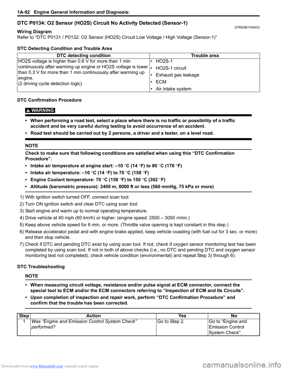
DTC P0134: O2 Sensor (HO2S) Circuit No Activity Detected (Sensor-1)S7RS0B1104033
Wiring Diagram
Refer to “DTC P0131 / P0132: O2 Sensor (HO2S) Circuit Low Voltage / High Voltage (Sensor-1)”
DTC Detecting Condition and Trouble Area
DTC Confirmation Procedure
WARNING!
• When performing a road test, select a place where there is no traffic or possibility of a traffic accident and be very careful during testing to avoid occurrence of an accident.
• Road test should be carried out by 2 persons, a driver and a tester, on a level road.
NOTE
Check to make sure that following conditions ar e satisfied when using this “DTC Confirmation
Procedure”.
• Intake air temperature at engine start: –10 °C (14 ° F) to 80 °C (176 °F)
• Intake air temperature: –10 °C (14 °F) to 70 °C (158 °F)
• Engine Coolant temperature: 70 °C (158 °F) to 150 °C (302 ° F)
• Altitude (barometric pressure): 2400 m, 8000 ft or less (560 mmHg, 75 kPa or more)
1) With ignition switch turned OFF, connect scan tool.
2) Turn ON ignition switch and clear DTC using scan tool.
3) Start engine and warm up to normal operating temperature.
4) Drive vehicle at 40 mph (60 km/h) or higher. (engine speed: 2500 – 3000 r/min.)
5) Keep above vehicle speed for 6 min. or more. (Throt tle valve opening is kept constant in this step.)
6) Release accelerator pedal and with engine brake applied, keep vehicle coasting (with fuel cut for 3 sec. or more)
and then stop vehicle.
7) Check if DTC and pending DTC exist by using scan tool. If not, check if oxygen sensor monitoring test has been
completed by using scan tool. If not in both of above c hecks (i.e., no DTC and pending DTC and oxygen sensor
monitoring test not completed), check vehicle cond ition (environmental) and repeat Step 3) through 6).
DTC Troubleshooting
NOTE
• When measuring circuit voltage, resistance and/ or pulse signal at ECM connector, connect the
special tool to ECM and/or the ECM connectors re ferring to “Inspection of ECM and Its Circuits”.
• Upon completion of inspection and repair work, perform “DTC Confirmation Procedure” and confirm that the trouble has been corrected.
DTC detecting condition Trouble area
HO2S voltage is higher than 0.6 V for more than 1 min
continuously after warming up engine or HO2S voltage is lower
than 0.3 V for more than 1 min continuously after warming up
engine.
(2 driving cycle detection logic) •HO2S-1
• HO2S-1 circuit
• Exhaust gas leakage
•ECM
• Air intake system
Step
Action YesNo
1 Was “Engine and Emission Control System Check”
performed? Go to Step 2.
Go to “Engine and
Emission Control
System Check”.