model battery SUZUKI SWIFT 2006 2.G Service User Guide
[x] Cancel search | Manufacturer: SUZUKI, Model Year: 2006, Model line: SWIFT, Model: SUZUKI SWIFT 2006 2.GPages: 1496, PDF Size: 34.44 MB
Page 382 of 1496
Downloaded from www.Manualslib.com manuals search engine 1G-7 Fuel System:
Fuel Pressure Relief ProcedureS7RS0B1706003
CAUTION!
This work must not be done when engine is
hot. If done so, it may cause adverse effect to
catalyst.
NOTE
If ECM detects DTC(s) after servicing, clear
DTC(s) referring to “DTC Clearance in
Section 1A”.
1) Make sure that engine is cold.
2) Shift transaxle gear shift lever in “Neutral” (shift select lever in “P” range for A/T model), set parking
brake and block drive wheels.
3) Remove relay / fuse box cover.
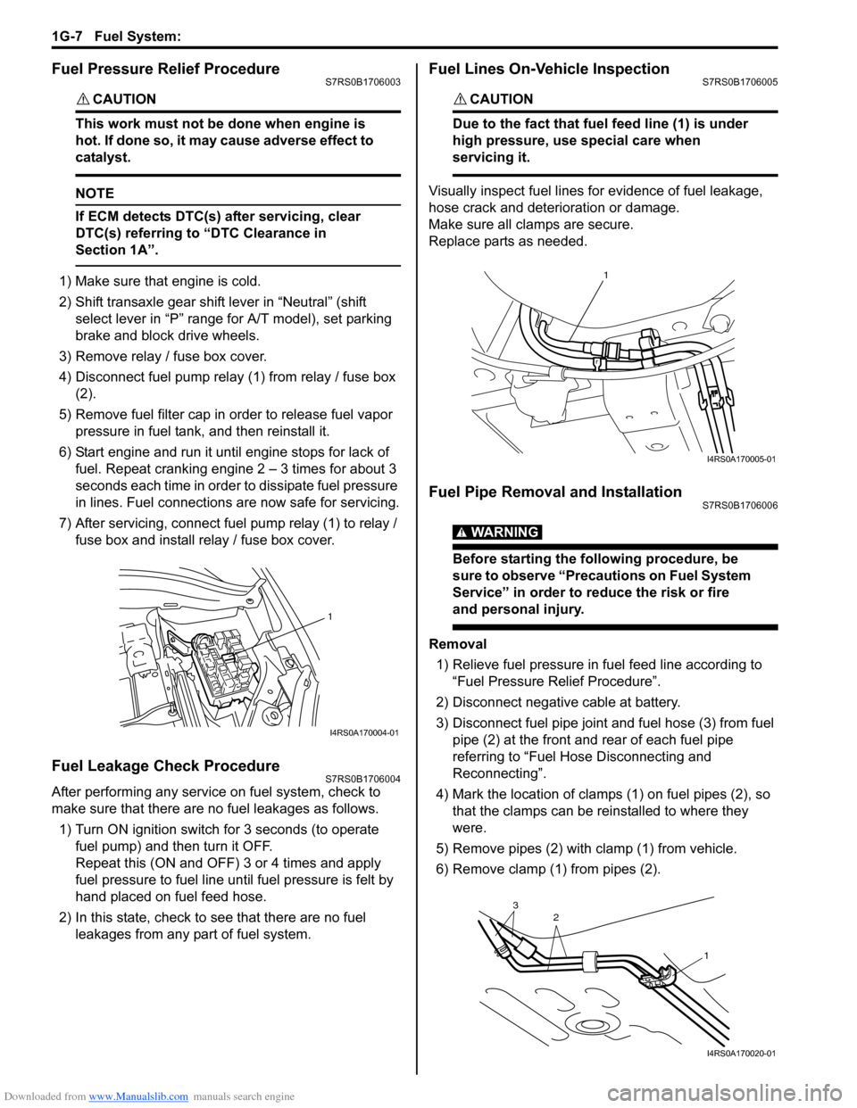
4) Disconnect fuel pump relay (1) from relay / fuse box (2).
5) Remove fuel filter cap in order to release fuel vapor pressure in fuel tank, and then reinstall it.
6) Start engine and run it until engine stops for lack of fuel. Repeat cranking engine 2 – 3 times for about 3
seconds each time in order to dissipate fuel pressure
in lines. Fuel connections are now safe for servicing.
7) After servicing, connect fuel pump relay (1) to relay / fuse box and install re lay / fuse box cover.
Fuel Leakage Check ProcedureS7RS0B1706004
After performing any service on fuel system, check to
make sure that there are no fuel leakages as follows.
1) Turn ON ignition switch for 3 seconds (to operate fuel pump) and then turn it OFF.
Repeat this (ON and OFF) 3 or 4 times and apply
fuel pressure to fuel line until fuel pressure is felt by
hand placed on fuel feed hose.
2) In this state, check to see that there are no fuel leakages from any part of fuel system.
Fuel Lines On-Vehicle InspectionS7RS0B1706005
CAUTION!
Due to the fact that fuel feed line (1) is under
high pressure, use special care when
servicing it.
Visually inspect fuel lines for evidence of fuel leakage,
hose crack and deterioration or damage.
Make sure all cl amps are secure.
Replace parts as needed.
Fuel Pipe Removal and InstallationS7RS0B1706006
WARNING!
Before starting the following procedure, be
sure to observe “Precautions on Fuel System
Service” in order to reduce the risk or fire
and personal injury.
Removal
1) Relieve fuel pressure in fuel feed line according to “Fuel Pressure Relief Procedure”.
2) Disconnect negative cable at battery.
3) Disconnect fuel pipe joint and fuel hose (3) from fuel pipe (2) at the front and rear of each fuel pipe
referring to “Fuel Hose Disconnecting and
Reconnecting”.
4) Mark the location of clamps (1) on fuel pipes (2), so that the clamps can be reinstalled to where they
were.
5) Remove pipes (2) with clamp (1) from vehicle.
6) Remove clamp (1) from pipes (2).
1
I4RS0A170004-01
1
I4RS0A170005-01
2
13
I4RS0A170020-01
Page 400 of 1496

Downloaded from www.Manualslib.com manuals search engine 1H-8 Ignition System:
Ignition Coil Assembly (Including ignitor)
Removal and Installation
S7RS0B1806005
Removal1) Disconnect negative (–) cable at battery.
2) Remove air cleaner assembly with air intake pipe and cylinder head upper cover.
3) Disconnect ignition coil coupler.
4) Disconnect high-tension cord (3) from ignition coil assembly (2).
5) Remove ignition coil bolts (1) and then pull out ignition coil assembly.
Installation 1) Install ignition coil assembly (2).
2) Tighten ignition coil bolts (1) to specified torque, and then connect igni tion coil coupler.
Tightening torque
Ignition coil bolt (a): 10 N·m (1.0 kgf-m, 7.5 lb-ft)
3) Install high-tension cord (3) to ignition coil assembly while gripping its cap.
4) Install cylinder head upper cover and air cleaner assembly with air intake pipe.
5) Connect negative (–) cable to battery.
Ignition Coil Assembly (Including ignitor)
Inspection
S7RS0B1806006
Measure secondary coil for resistance.
If resistance is out of specification, replace ignition coil
assembly.
Secondary coil resistance
7.5 – 10.3 k Ω at 20 °C, 68 ° F
Ignition Timing InspectionS7RS0B1806007
NOTE
• Ignition timing is not adjustable. If ignition
timing is out of specification, check
system related parts.
• Before starting engine, place transmission gear shift lever in “Neutral” (shift selector
lever to “P” range for A/T model), and set
parking brake.
1) Connect scan tool to DLC (1) with ignition switch OFF.
Special tool
(A): SUZUKI scan tool
2) Start engine and warm it up to normal operating temperature.
3) Make sure that all of electrical loads except ignition are switched off.
4) Check to be sure that idle speed is within specification referring to “Idle Speed and IAC
Throttle Valve Opening Inspection in Section 1A”
5) Fix ignition timing by using “Fixed Spark” of “Misc Test” mode on scan tool.
I2RH0B180006-01
I3RM0A180004-01
I2RH0B180007-01
(A)
1
I4RS0B180003-01
Page 405 of 1496
Downloaded from www.Manualslib.com manuals search engine Starting System: 1I-4
Repair Instructions
Starting Motor Dismounting and RemountingS7RS0B1906001
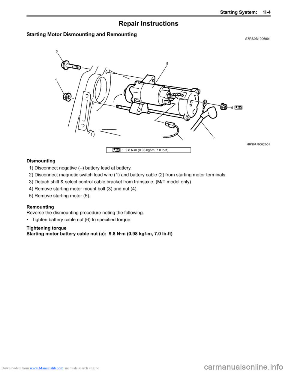
Dismounting1) Disconnect negative (–) battery lead at battery.
2) Disconnect magnetic switch lead wire (1) and battery cable (2) from starting motor terminals.
3) Detach shift & select control cable bracket from transaxle. (M/T model only)
4) Remove starting motor mount bolt (3) and nut (4).
5) Remove starting motor (5).
Remounting
Reverse the dismounting procedure noting the following.
• Tighten battery cable nut (6) to specified torque.
Tightening torque
Starting motor battery cable nut (a): 9.8 N·m (0.98 kgf-m, 7.0 lb-ft)
I4RS0A190002-01
: 9.8 N ⋅m (0.98 kgf-m, 7.0 lb-ft)
Page 416 of 1496
Downloaded from www.Manualslib.com manuals search engine 1J-6 Charging System:
Generator Test (Overcharged Battery Check)S7RS0B1A04004
1) To determine battery condition, refer to “Battery Description”.
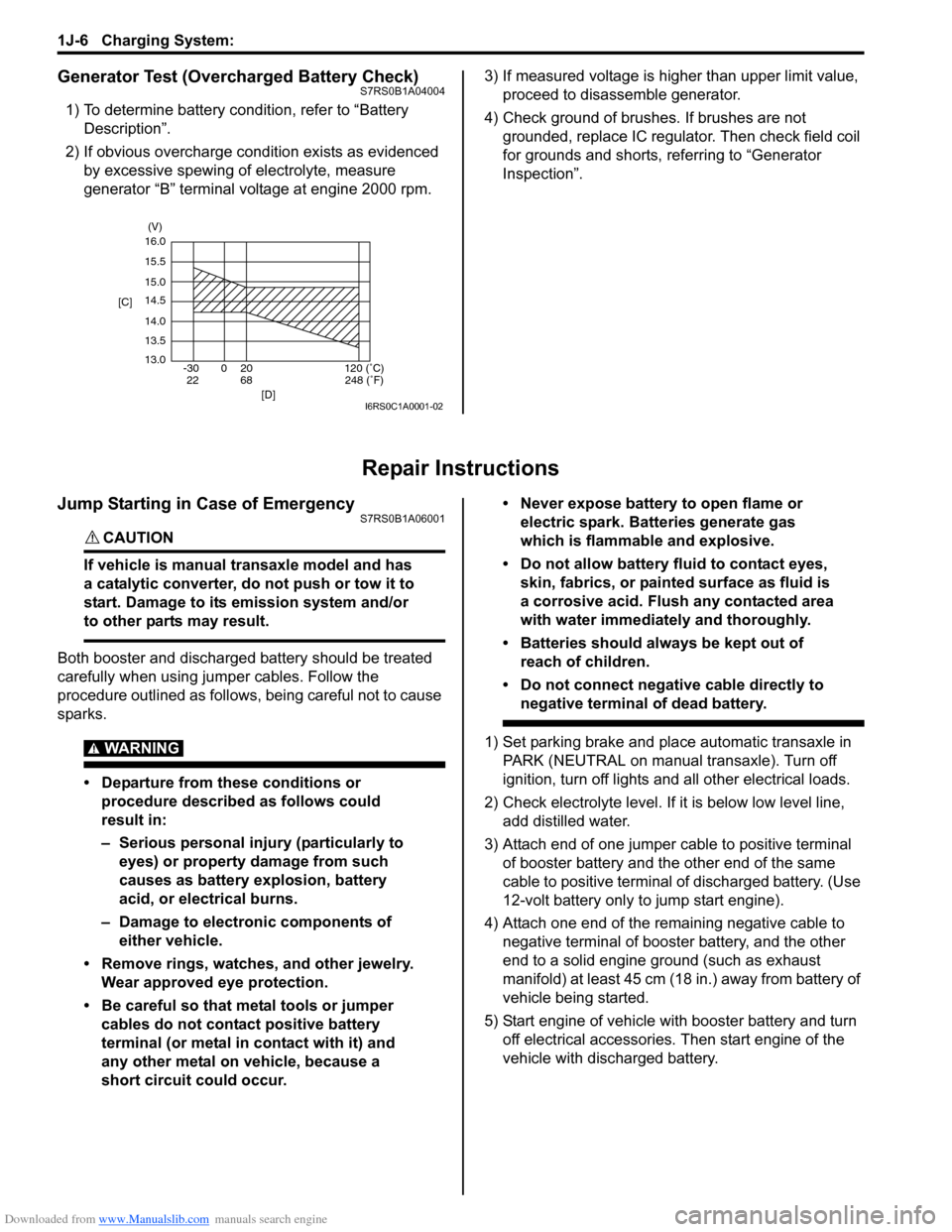
2) If obvious overcharge condition exists as evidenced by excessive spewing of electrolyte, measure
generator “B” terminal voltage at engine 2000 rpm. 3) If measured voltage is higher than upper limit value,
proceed to disassemble generator.
4) Check ground of brushes. If brushes are not grounded, replace IC regulator. Then check field coil
for grounds and shorts, referring to “Generator
Inspection”.
Repair Instructions
Jump Starting in Case of EmergencyS7RS0B1A06001
CAUTION!
If vehicle is manual transaxle model and has
a catalytic converter, do not push or tow it to
start. Damage to its emission system and/or
to other parts may result.
Both booster and discharged battery should be treated
carefully when using ju mper cables. Follow the
procedure outlined as follows, being careful not to cause
sparks.
WARNING!
• Departure from these conditions or procedure described as follows could
result in:
– Serious personal injury (particularly to eyes) or property damage from such
causes as battery explosion, battery
acid, or electrical burns.
– Damage to electronic components of either vehicle.
• Remove rings, watches, and other jewelry. Wear approved eye protection.
• Be careful so that metal tools or jumper cables do not contact positive battery
terminal (or metal in contact with it) and
any other metal on vehicle, because a
short circuit could occur. • Never expose battery to open flame or
electric spark. Batteries generate gas
which is flammable and explosive.
• Do not allow battery fluid to contact eyes, skin, fabrics, or painted surface as fluid is
a corrosive acid. Flush any contacted area
with water immediately and thoroughly.
• Batteries should always be kept out of reach of children.
• Do not connect negative cable directly to negative terminal of dead battery.
1) Set parking brake and place automatic transaxle in PARK (NEUTRAL on manual transaxle). Turn off
ignition, turn off lights and all other electrical loads.
2) Check electrolyte level. If it is below low level line, add distilled water.
3) Attach end of one jumper cable to positive terminal of booster battery and the other end of the same
cable to positive terminal of discharged battery. (Use
12-volt battery only to jump start engine).
4) Attach one end of the remaining negative cable to negative terminal of booster battery, and the other
end to a solid engine ground (such as exhaust
manifold) at least 45 cm (18 in.) away from battery of
vehicle being started.
5) Start engine of vehicle with booster battery and turn off electrical accessories. Then start engine of the
vehicle with discharged battery.
16.0
15.5
15.0
14.5
14.0
13.5
13.0 -30 0 20
[C]
[D]
68
22120 (˚C)
248 (˚F)
(V)
I6RS0C1A0001-02
Page 880 of 1496
Downloaded from www.Manualslib.com manuals search engine 6B-9 Steering Wheel and Column:
Ignition Switch Cylinder Assembly Removal
and Installation (Non- Keyless Start Model)
S7RS0B6206008
Removal1) Disconnect negative (–) cable at battery.
2) Disable air bag system referring to “Disabling Air Bag System in Section 8B”.
3) Remove steering column upper and lower covers.
4) Remove immobilizer co ntrol module referring to
“Immobilizer Control Modu le (ICM) Removal and
Installation in Section 10C”.
5) Remove ignition switch cy linder assembly as follows.
a) Turn ignition key to “ACC” position.
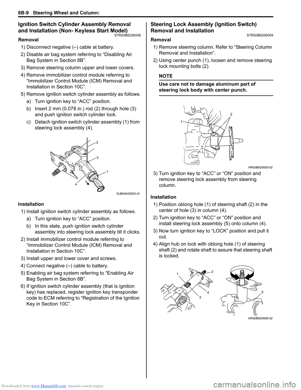
b) Insert 2 mm (0.078 in.) rod (2) through hole (3) and push ignition switch cylinder lock.
c) Detach ignition switch cylinder assembly (1) from steering lock assembly (4).
Installation 1) Install ignition switch cy linder assembly as follows.
a) Turn ignition key to “ACC” position.
b) In this state, push ignition switch cylinder assembly into steering lock assembly till it clicks.
2) Install immobilizer cont rol module referring to
“Immobilizer Control Modu le (ICM) Removal and
Installation in Section 10C”.
3) Install upper and lower cover and screws.
4) Connect negative (–) cable to battery.
5) Enabling air bag system referring to “Enabling Air Bag System in Section 8B”.
6) If ignition switch cylinder assembly (that is ignition
key) has replaced, register ignition key transponder
code to ECM referring to “R egistration of the Ignition
Key in Section 10C”.
Steering Lock Assembly (Ignition Switch)
Removal and Installation
S7RS0B6206009
Removal
1) Remove steering column. Refer to “Steering Column
Removal and Installation”.
2) Using center punch (1), loosen and remove steering lock mounting bolts (2).
NOTE
Use care not to damage aluminum part of
steering lock body with center punch.
3) Turn ignition key to “ACC” or “ON” position and remove steering lock a ssembly from steering
column.
Installation 1) Position oblong hole (1) of steering shaft (2) in the center of hole (3) in column (4).
2) Turn ignition key to “ACC” or “ON” position and install steering lock assemb ly (5) onto column (4).
3) Now turn ignition key to “LOCK” position and pull it out.
4) Align hub on lock with oblong hole (1) of steering shaft (2) and rotate shaft to assure that steering shaft
is locked.
2
3
1
4
I5JB0A620025-01
I4RS0B620005-02
1
32
4
5
I4RS0B620006-02
Page 928 of 1496
Downloaded from www.Manualslib.com manuals search engine 6C-46 Power Assisted Steering System:
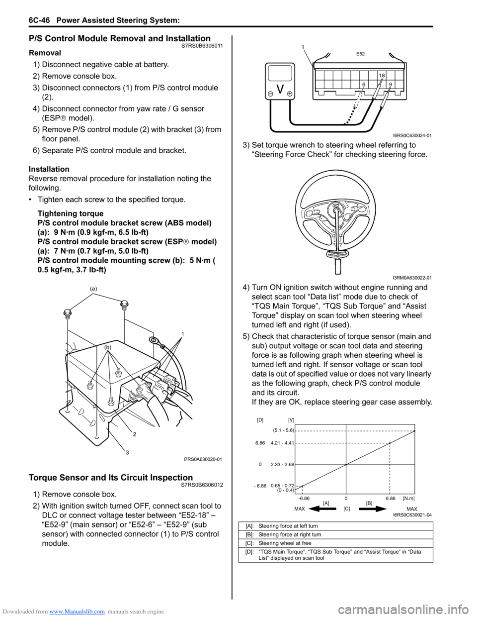
P/S Control Module Removal and InstallationS7RS0B6306011
Removal1) Disconnect negative cable at battery.
2) Remove console box.
3) Disconnect connectors (1) from P/S control module (2).
4) Disconnect connector from yaw rate / G sensor
(ESP ® model).
5) Remove P/S control module (2) with bracket (3) from floor panel.
6) Separate P/S control module and bracket.
Installation
Reverse removal procedure for installation noting the
following.
• Tighten each screw to the specified torque. Tightening torque
P/S control module bracket screw (ABS model)
(a): 9 N·m (0.9 kgf-m, 6.5 lb-ft)
P/S control module bracket screw (ESP ® model)
(a): 7 N·m (0.7 kgf-m, 5.0 lb-ft)
P/S control module mounting screw (b): 5 N·m (
0.5 kgf-m, 3.7 lb-ft)
Torque Sensor and Its Circuit InspectionS7RS0B6306012
1) Remove console box.
2) With ignition switch turned OFF, connect scan tool to DLC or connect voltage tester between “E52-18” –
“E52-9” (main sensor) or “E52-6” – “E52-9” (sub
sensor) with connected connector (1) to P/S control
module. 3) Set torque wrench to stee
ring wheel referring to
“Steering Force Check” for checking steering force.
4) Turn ON ignition switch without engine running and select scan tool “Data list” mode due to check of
“TQS Main Torque”, “TQS Sub Torque” and “Assist
Torque” display on scan tool when steering wheel
turned left and right (if used).
5) Check that characteristic of torque sensor (main and sub) output voltage or scan tool data and steering
force is as following graph when steering wheel is
turned left and right. If sensor voltage or scan tool
data is out of specified value or does not vary linearly
as the following graph, check P/S control module
and its circuit.
If they are OK, replace steering gear case assembly.
1
(a)
2
3
(b)
I7RS0A630020-01
[A]: Steering force at left turn
[B]: Steering force at right turn
[C]: Steering wheel at free
[D]: “TQS Main Torque”, “TQS Sub Torque” and “Assist Torque” in “Data List” displayed on scan tool
E52
18
9
6
9
6 18
1
I6RS0C630024-01
I3RM0A630022-01
0
[C] [N.m]
MAX MAX
[B]
[A]
2.33 - 2.68 [V]
[D]
0.65 - 0.72
(0 - 0.4)
4.21 - 4.41
(5.1 - 5.6)
6.86
-6.86
0
6.86
- 6.86
I6RS0C630021-04
Page 1023 of 1496
Downloaded from www.Manualslib.com manuals search engine Air Conditioning System: Automatic Type 7B-75
6) Connect connector to air flow control actuator.
7) Set air flow selector of HVAC control module to VENT position with ignition switch ON, and make
sure if the position of act uator lever is VENT position
(8).
8) Turn ignition switch OFF, and then disconnect connector from air flow control actuator.
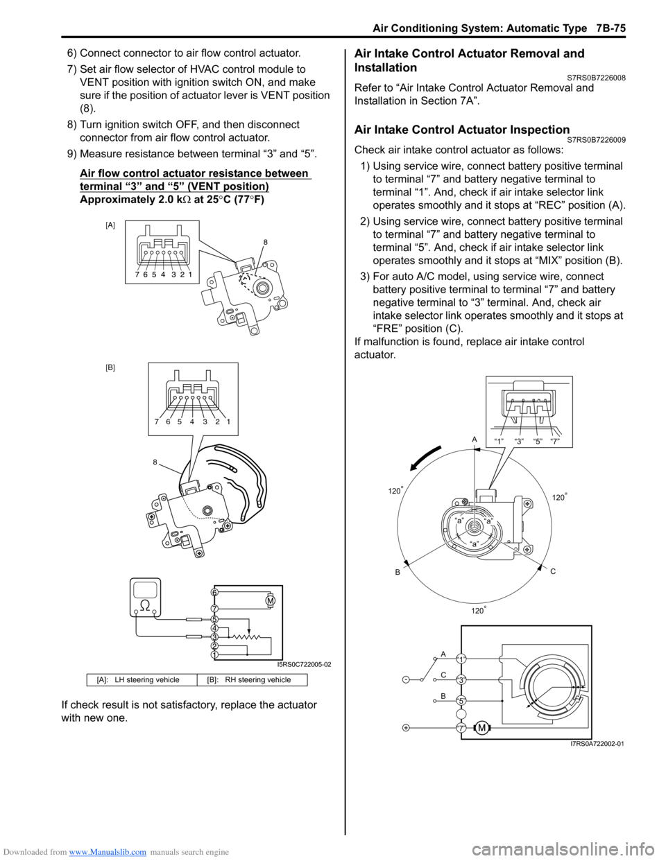
9) Measure resistance between terminal “3” and “5”.
Air flow control actuator resistance between
terminal “3” and “5” (VENT position)
Approximately 2.0 k Ω at 25 °C (77 °F)
If check result is not satisfactory, replace the actuator
with new one.
Air Intake Control Actuator Removal and
Installation
S7RS0B7226008
Refer to “Air Intake Control Actuator Removal and
Installation in Section 7A”.
Air Intake Control Actuator InspectionS7RS0B7226009
Check air intake contro l actuator as follows:
1) Using service wire, connect battery positive terminal
to terminal “7” and battery negative terminal to
terminal “1”. And, check if air intake selector link
operates smoothly and it stops at “REC” position (A).
2) Using service wire, connect battery positive terminal
to terminal “7” and battery negative terminal to
terminal “5”. And, check if air intake selector link
operates smoothly and it stops at “MIX” position (B).
3) For auto A/C model, using service wire, connect battery positive terminal to terminal “7” and battery
negative terminal to “3” terminal. And, check air
intake selector link operates smoothly and it stops at
“FRE” position (C).
If malfunction is found, replace air intake control
actuator.
[A]: LH steering vehicl e [B]: RH steering vehicle
[A]
[B]
8
8765 4 3 21
I5RS0C722005-02
A
C
B“a”
“a”“a”
-
+
A
C
B “1” “3” “5” “7”
“1”
“3”
“5”
“7”
120
°
120° 120
°
I7RS0A722002-01
Page 1341 of 1496
Downloaded from www.Manualslib.com manuals search engine Glass / Windows / Mirrors: 9E-14
Rear End Door Window Defogger Switch
Inspection
S7RS0B9506012
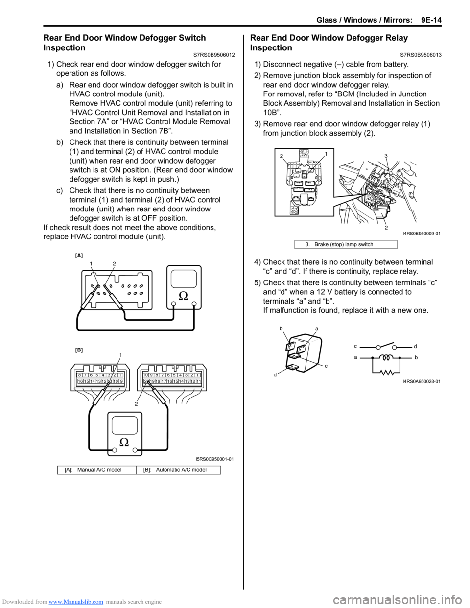
1) Check rear end door window defogger switch for operation as follows.
a) Rear end door window defogger switch is built in HVAC control module (unit).
Remove HVAC control module (unit) referring to
“HVAC Control Unit Removal and Installation in
Section 7A” or “HVAC Control Module Removal
and Installation in Section 7B”.
b) Check that there is continuity between terminal (1) and terminal (2) of HVAC control module
(unit) when rear end door window defogger
switch is at ON position. (Rear end door window
defogger switch is kept in push.)
c) Check that there is no continuity between terminal (1) and terminal (2) of HVAC control
module (unit) when rear end door window
defogger switch is at OFF position.
If check result does not meet the above conditions,
replace HVAC control module (unit).
Rear End Door Window Defogger Relay
Inspection
S7RS0B9506013
1) Disconnect negative (–) cable from battery.
2) Remove junction block assembly for inspection of rear end door window defogger relay.
For removal, refer to “BCM (Included in Junction
Block Assembly) Removal a nd Installation in Section
10B”.
3) Remove rear end door window defogger relay (1) from junction block assembly (2).
4) Check that there is no continuity between terminal “c” and “d”. If there is continuity, replace relay.
5) Check that there is continuity between terminals “c” and “d” when a 12 V battery is connected to
terminals “a” and “b”.
If malfunction is found, replace it with a new one.
[A]: Manual A/C model [B]: Automatic A/C model
12
7812910
65 431516 14 13 12 11789101920121112
65 431718 16 15 14 13
1
2
[A]
[B]
I5RS0C950001-01
3. Brake (stop) lamp switch
1
3
2
2
I4RS0B950009-01
ba
c
dc
a
d
bI4RS0A950028-01
Page 1404 of 1496
Downloaded from www.Manualslib.com manuals search engine 10B-1 Body Electrical Control System:
Control Systems
Body Electrical Control System
Precautions
Precautions in Diagnosing TroubleS7RS0BA200001
• Diagnostic information stored in BCM memory can be cleared as well as checked by using SUZUKI scan tool.
Before using scan tool, read its Operator ’s (Instruction) Manual carefully to have good understanding as to what
functions are available and how to use it.
• Be sure to read “Precautions for Electrical Circuit Serv ice in Section 00” before inspection and observe what is
written there.
• Communication of ECM, TCM (if equipped), ABS/ESP ® control module, steering angle sensor (ESP ® model),
keyless start control module (if equipped), combinatio n meter and BCM is established by CAN (Controller Area
Network). For detail of CAN communication for BCM, refer to “CAN Communication System Description”.
Therefore, handle CAN communication line with care referr ing to “Precaution for CAN Communication System in
Section 00”.
General Description
BCM General DescriptionS7RS0BA201001
The Body electrical Control Module (BCM) is incorporated in junction block assembly. Do not attempt removal of BCM
from junction block assembly as it may cause contact failure.
The BCM incorporates relays and controllers which are used for the following systems and controls them.
• Power door lock
• Keyless entry (if equipped)
• Door lock function of keyle ss start system (if equipped)
• Rear wiper
• Combination meter
• Interior light
• Warning buzzer
• Rear end door window defogger and door mirror heater (if equipped)
• Rear end door opener
• Theft deterrent light
Also, the BCM has a function to cause the interior light and open door warning lamp in the combination meter to turn
off when any door is left open for longer than 15 minutes to reduce wasteful battery consumption.
In addition, it is possible to check operation of actuator whic h is controlled by BCM by using the output test function of
SUZUKI scan tool to operate actuator simulatively.
Page 1409 of 1496
![SUZUKI SWIFT 2006 2.G Service User Guide Downloaded from www.Manualslib.com manuals search engine Body Electrical Control System: 10B-6
[A]: Vehicle not equipped with diagnosis connector 19. Door key cylinder switch (included in door lock a SUZUKI SWIFT 2006 2.G Service User Guide Downloaded from www.Manualslib.com manuals search engine Body Electrical Control System: 10B-6
[A]: Vehicle not equipped with diagnosis connector 19. Door key cylinder switch (included in door lock a](/img/20/7607/w960_7607-1408.png)
Downloaded from www.Manualslib.com manuals search engine Body Electrical Control System: 10B-6
[A]: Vehicle not equipped with diagnosis connector 19. Door key cylinder switch (included in door lock actuator)40. SDM
[B]: Vehicle equipped with diagnosis conn ector 20. Manual door lock switch 41. Rear end door window defogger relay
[C]: ESP ® model 21. Rear end door window defogger switch 42. Rear end door window defogger
1. BCM (included in junction block assembly) 22. Rear end door opener switch 43. Rear end door window defogger indicator lamp
2. Rear washer motor 23. “3” position switch (A/T model)44. Horn relay
3. Rear wiper motor 24. A/C switch45. Horn switch
4. Rear wiper relay 25. Rear end door opener relay46. Horn
5. Rear wiper and washer switch 26. Rear end door opener actuator47. Lighting switch
6. Outside air temperature sensor 27. TCM (A/T model)48. Ignition switch
7. Key reminder switch 28. ECM49. Battery
8. Theft deterrent light 29. Combination meter50. To turn signal light
9. Oil pressure switch 30. Data link connector (DLC)51. Body ground
10. Generator 31. To ECM, ABS/ESP®, P/S control module 52. Engine ground
11. Information display (if equipped) 32. To SDM53. Keyless start control module (if equipped)
12. Keyless entry receiver (if equipped) 33. Door lock actuator relay 54. Right side door mirror heater (if equipped)
13. Driver side door switch 34. Driver side door lock actuator55. Left side door mirror heater (if equipped)
14. Other than driver side door switch 35. Passenger side door lock actuator56. ABS/ESP® control module
15. Rear end door switch 36. Rear door lock actuator57. To HVAC control module
16. Driver side seat belt switch 37. Turn signal and hazard warning relay 58. CAN junction connector
17. Brake fluid level switch 38. Hazard warning switch59. Steering angle sensor
18. Parking brake switch 39. Interior light