passing SUZUKI SWIFT 2006 2.G Service User Guide
[x] Cancel search | Manufacturer: SUZUKI, Model Year: 2006, Model line: SWIFT, Model: SUZUKI SWIFT 2006 2.GPages: 1496, PDF Size: 34.44 MB
Page 1048 of 1496

Downloaded from www.Manualslib.com manuals search engine 8B-10 Air Bag System:
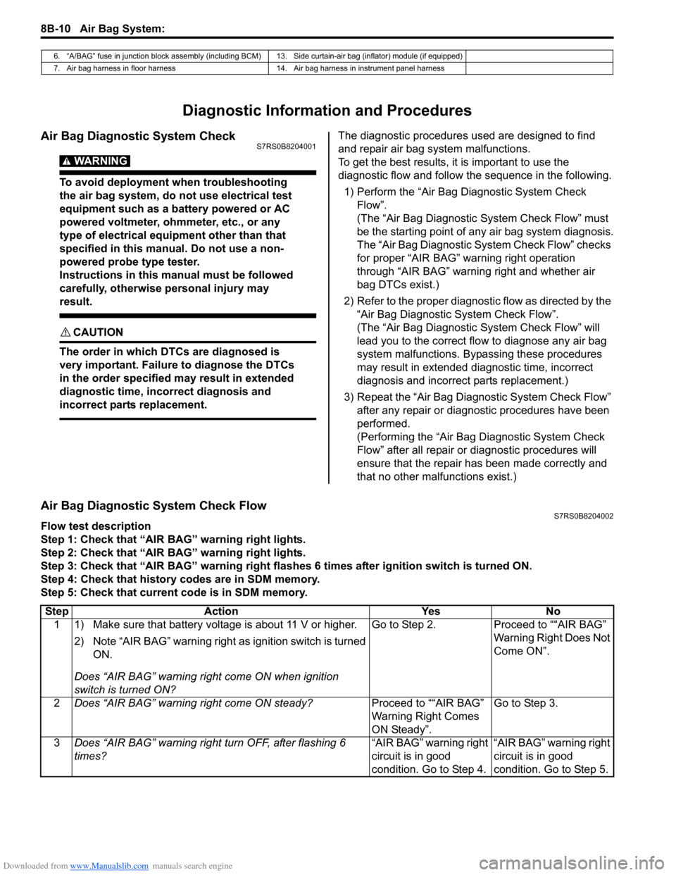
Diagnostic Information and Procedures
Air Bag Diagnostic System CheckS7RS0B8204001
WARNING!
To avoid deployment when troubleshooting
the air bag system, do not use electrical test
equipment such as a battery powered or AC
powered voltmeter, ohmmeter, etc., or any
type of electrical equipment other than that
specified in this manual. Do not use a non-
powered probe type tester.
Instructions in this manual must be followed
carefully, otherwise personal injury may
result.
CAUTION!
The order in which DTCs are diagnosed is
very important. Failure to diagnose the DTCs
in the order specified may result in extended
diagnostic time, incorrect diagnosis and
incorrect parts replacement.
The diagnostic procedures used are designed to find
and repair air bag system malfunctions.
To get the best results, it is important to use the
diagnostic flow and follow the sequence in the following.1) Perform the “Air Bag Diagnostic System Check Flow”.
(The “Air Bag Diagnostic System Check Flow” must
be the starting point of any air bag system diagnosis.
The “Air Bag Diagnostic System Check Flow” checks
for proper “AIR BAG” warning right operation
through “AIR BAG” warning right and whether air
bag DTCs exist.)
2) Refer to the proper diagnost ic flow as directed by the
“Air Bag Diagnostic System Check Flow”.
(The “Air Bag Diagnostic System Check Flow” will
lead you to the correct flow to diagnose any air bag
system malfunctions. Bypassing these procedures
may result in extended diagnostic time, incorrect
diagnosis and incorrect parts replacement.)
3) Repeat the “Air Bag Diagnostic System Check Flow” after any repair or diagnostic procedures have been
performed.
(Performing the “Air Bag Diagnostic System Check
Flow” after all repair or diagnostic procedures will
ensure that the repair has been made correctly and
that no other malfunctions exist.)
Air Bag Diagnostic System Check FlowS7RS0B8204002
Flow test description
Step 1: Check that “AIR BAG” warning right lights.
Step 2: Check that “AIR BAG” warning right lights.
Step 3: Check that “AIR BAG” warning right flas hes 6 times after ignition switch is turned ON.
Step 4: Check that history codes are in SDM memory.
Step 5: Check that current code is in SDM memory.
6. “A/BAG” fuse in junction block assembly (including BCM) 13. Side curtain-air bag (inflator) module (if equipped)
7. Air bag harness in floor harness 14. Air bag harness in instrument panel harness
Step Action YesNo
1 1) Make sure that battery voltage is about 11 V or higher.
2) Note “AIR BAG” warning right as ignition switch is turned
ON.
Does “AIR BAG” warning ri ght come ON when ignition
switch is turned ON? Go to Step 2.
Proceed to ““AIR BAG”
Warning Right Does Not
Come ON”.
2 Does “AIR BAG” warning right come ON steady? Proceed to ““AIR BAG”
Warning Right Comes
ON Steady”.Go to Step 3.
3 Does “AIR BAG” warning right turn OFF, after flashing 6
times? “AIR BAG” warning right
circuit is in good
condition. Go to Step 4.“AIR BAG” warning right
circuit is in good
condition. Go to Step 5.
Page 1245 of 1496

Downloaded from www.Manualslib.com manuals search engine Wiring Systems: 9A-74
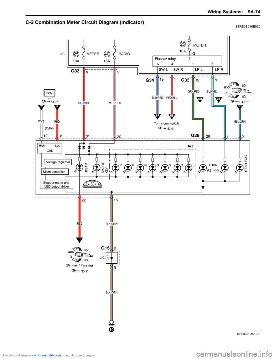
C-2 Combination Meter Circuit Diagram (Indicator)S7RS0B910E020
RADIO
15A40METER
10A25
WHT/RED
32
31 5
Stepper motor and
LED output driver
Voltage regulator
Micro controllerSMART
KEY
G336
RED/BLK
"D-1"
BEAM
REAR FOG
22 A/T
RED
(Dimmer / Passing)
(CAN)
J/B
L23DNRP
16
B
B
BLK /ORN
BLK /ORN
J/C
G15
10
CAN
High Low
R
G28
WHTREDBLU/ORN
"A-8""D-10"RW
10 8
BCM
261
"D-6"
TURN
(R)
GRN/REDBLU/YEL
912G33
1
64
SW-L SW-R LP-L IG
LP-R
Flasher relay
5
7
119G34
10A METER
Turn signal switch
25
RED/BLUBLU/RED
21
GR
RB
BO
BR
(L)
BY
I6RS0C910921-01
Page 1248 of 1496

Downloaded from www.Manualslib.com manuals search engine 9A-77 Wiring Systems:
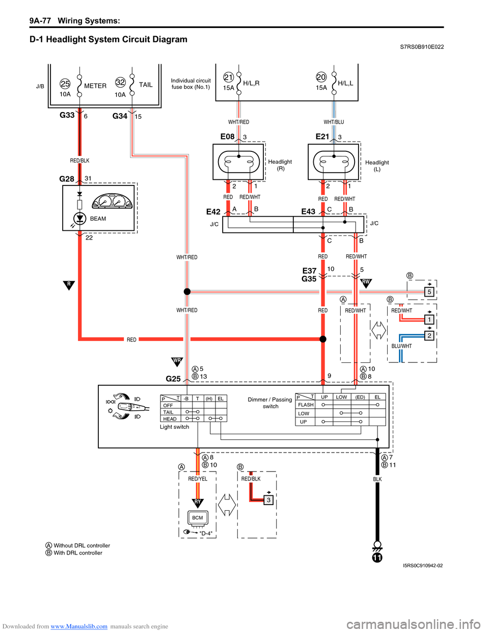
D-1 Headlight System Circuit DiagramS7RS0B910E022
1
Headlight (R) Headlight
(L)
WHT/BLU
RED
Dimmer / Passing switch
Light switch
2
2
BA BC
B
C
33
15
1
22G28
E08
G34
E21
G336
31
RED/BLK
WHT/RED
WHT/RED
10A
25METER
WHT/RED
9
BLK
11
G25
15A
21
15A
20H/L,R H/L,L
RED/WHTRED
10
RED
RED
J/B
10ATAIL
32
RED/WHTRED/WHT
BLU/WHT
5
RED/WHT
E37
G35
E42
J/C
REDRED/WHT
BEAM
FLASH UPLOW
T
P(ED)EL
UP
LOW
OFF
TAIL
HEAD -BT
T
P(H) EL
RY
RED/YEL
"D-4"
BCM
R
WR
RW
E43
J/C
Individual circuit
fuse box (No.1)
Without DRL controller
AWith DRL controller
B
A
5
1
2
3
AB
B
RED/BLK
B
AB5
13AB10
8
AB7
11AB8
10
I5RS0C910942-02