Vin SUZUKI SWIFT 2006 2.G Service Workshop Manual
[x] Cancel search | Manufacturer: SUZUKI, Model Year: 2006, Model line: SWIFT, Model: SUZUKI SWIFT 2006 2.GPages: 1496, PDF Size: 34.44 MB
Page 1150 of 1496

Downloaded from www.Manualslib.com manuals search engine 8B-112 Air Bag System:
• Check sensor (1) for dents, crack, deformation.
• Check sensor connector (sensor side and harness side), lock mechanism or sensor lead wire for
damage, crack, scorching or melting.
• Check connector terminals for bent, corrosion or rust. If any faulty condition is found in above checks,
replace.
Passenger Air Bag (Inflator) Module Repair
Harness Installation
S7RS0B8206017
Replace passenger air bag (inflator) module repair
harness (4) according to the following procedure when
the harness (1) connect ed with passenger air bag
(inflator) module of the air bag harness included in
instrument panel harness (2) and passenger air bag
(inflator) module connector (3) is damaged. 1) Disable air bag system. Re
fer to “Disabling Air Bag
System”.
2) Disconnect “L32” connector from floor harness located near the glove box.
3) Cut off passenger air bag (inflator) module harness (1) included in instrument panel harness (2) as
shown, and then fasten it to instrument panel
harness with vinyl tape for avoiding interference with
other parts.
4) Install passenger air bag (inflator) module repair harness (1) to floor harness (2), instrument panel
harness (3) and passenger air bag (inflator) module.CAUTION!
To avoid interference with other parts, fasten
the repair harness to in strument wire harness
with a clamp or vinyl tape as shown in figure.
5) Connect each connector securely till click is heard.
5. Driver air bag (inflator) module 7. Floor harness
6. Passenger air bag (inflator) module 8. Vinyl tape
1I4RS0A820082-01
7
4
6
6
2
28
1
3
5
5
7I4RS0A820103-01
1
I4RS0A820083-01
1
2
3
I4RS0A820085-01
Page 1152 of 1496
Downloaded from www.Manualslib.com manuals search engine 8B-114 Air Bag System:
Deployment / Activation Outside of Vehicle
When you intend to return the vehicle to service, deploy
the air bag (inflator) module(s) or activate seat belt
pretensioner(s) outside of the vehicle.1) Turn ignition switch to LOCK position and remove key.
2) Wear safety glasses during this deployment / activation procedure.
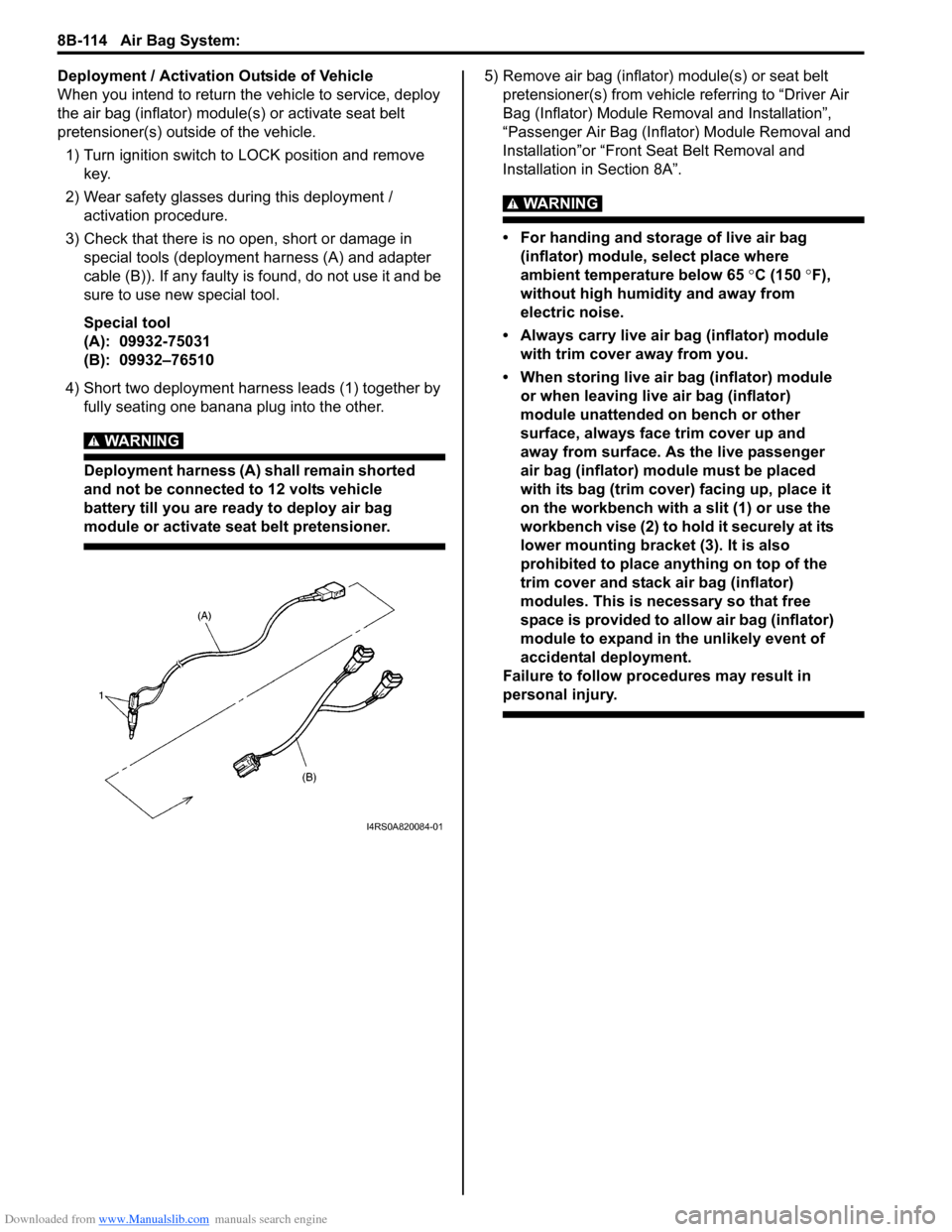
3) Check that there is no open, short or damage in special tools (deployment harness (A) and adapter
cable (B)). If any faulty is found, do not use it and be
sure to use new special tool.
Special tool
(A): 09932-75031
(B): 09932–76510
4) Short two deployment harness leads (1) together by fully seating one banana plug into the other.
WARNING!
Deployment harness (A) shall remain shorted
and not be connected to 12 volts vehicle
battery till you are ready to deploy air bag
module or activate seat belt pretensioner.
5) Remove air bag (inflator) module(s) or seat belt pretensioner(s) from vehicle referring to “Driver Air
Bag (Inflator) Module Re moval and Installation”,
“Passenger Air Bag (Inflator) Module Removal and
Installation”or “Front Seat Belt Removal and
Installation in Section 8A”.
WARNING!
• For handing and storage of live air bag (inflator) module, select place where
ambient temperature below 65 °C (150 °F),
without high humidity and away from
electric noise.
• Always carry live air bag (inflator) module with trim cover away from you.
• When storing live air bag (inflator) module or when leaving live air bag (inflator)
module unattended on bench or other
surface, always face trim cover up and
away from surface. As the live passenger
air bag (inflator) module must be placed
with its bag (trim cover) facing up, place it
on the workbench with a slit (1) or use the
workbench vise (2) to hold it securely at its
lower mounting bracket (3). It is also
prohibited to place anything on top of the
trim cover and stack air bag (inflator)
modules. This is necessary so that free
space is provided to allow air bag (inflator)
module to expand in the unlikely event of
accidental deployment.
Failure to follow procedures may result in
personal injury.
I4RS0A820084-01
Page 1153 of 1496
Downloaded from www.Manualslib.com manuals search engine Air Bag System: 8B-115
WARNING!
• For handling and storage of seat belt pretensioner, select place where ambient
temperature is below 65 °C (150 °F),
without high humidity and away from
electric noise.
• Never carry seat belt pretensioner by webbing.
• When placing seat belt pretensioner on workbench or other surface, be sure to lay
it with its exhaust hole (1) side facing up. It
is also prohibited to put something on seat
belt pretensioner.
Otherwise, personal injury may result.
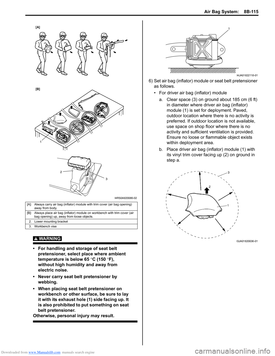
6) Set air bag (inflator) module or seat belt pretensioner
as follows.
• For driver air bag (inflator) module
a. Clear space (3) on ground about 185 cm (6 ft) in diameter where driver air bag (inflator)
module (1) is set for deployment. Paved,
outdoor location where there is no activity is
preferred. If outdoor location is not available,
use space on shop floor where there is no
activity and sufficient ventilation is provided.
Ensure no loose or flammable object exists
within deployment area.
b. Place driver air bag (inflator) module (1) with its vinyl trim cover facing up (2) on ground in
step a.
[A]: Always carry air bag (inflator) module with trim cover (air bag opening) away from body.
[B]: Always place air bag (inflator) module on workbench with trim cover (air bag opening) up, away from loose objects.
2. Lower mounting bracket
3. Workbench vise
1
2
3
[A]
[B]
I4RS0A820086-02
1
I4JA01822118-01
I3JA01820036-01
Page 1156 of 1496
Downloaded from www.Manualslib.com manuals search engine 8B-118 Air Bag System:
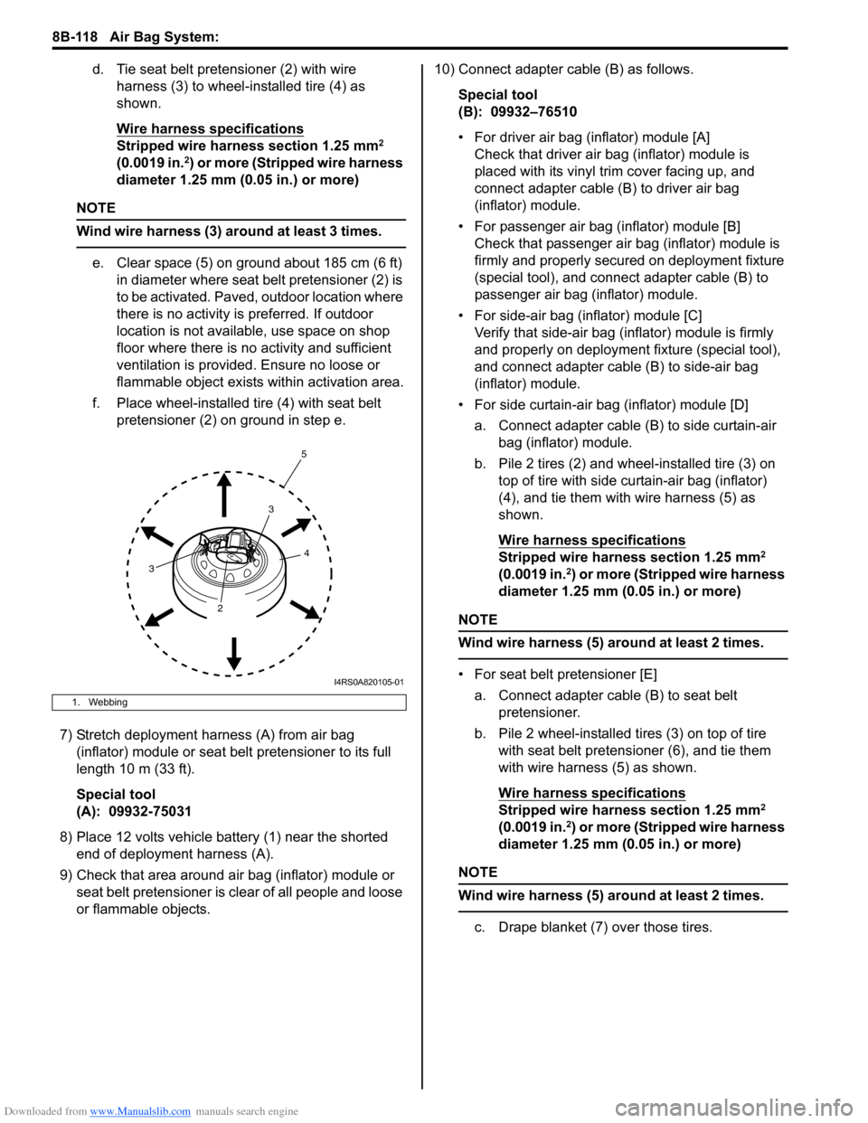
d. Tie seat belt pretensioner (2) with wire harness (3) to wheel-installed tire (4) as
shown.
Wire harness specifications
Stripped wire harness section 1.25 mm2
(0.0019 in.2) or more (Stripped wire harness
diameter 1.25 mm (0.05 in.) or more)
NOTE
Wind wire harness (3) around at least 3 times.
e. Clear space (5) on ground about 185 cm (6 ft) in diameter where seat belt pretensioner (2) is
to be activated. Paved, outdoor location where
there is no activity is preferred. If outdoor
location is not available, use space on shop
floor where there is no activity and sufficient
ventilation is provided. Ensure no loose or
flammable object exists within activation area.
f. Place wheel-installed tire (4) with seat belt pretensioner (2) on ground in step e.
7) Stretch deployment harness (A) from air bag (inflator) module or seat belt pretensioner to its full
length 10 m (33 ft).
Special tool
(A): 09932-75031
8) Place 12 volts vehicle battery (1) near the shorted end of deployment harness (A).
9) Check that area around air bag (inflator) module or seat belt pretensioner is clear of all people and loose
or flammable objects. 10) Connect adapter cable (B) as follows.
Special tool
(B): 09932–76510
• For driver air bag (inflator) module [A]Check that driver air bag (inflator) module is
placed with its vinyl trim cover facing up, and
connect adapter cable (B) to driver air bag
(inflator) module.
• For passenger air bag (inflator) module [B] Check that passenger air bag (inflator) module is
firmly and properly secured on deployment fixture
(special tool), and connect adapter cable (B) to
passenger air bag (inflator) module.
• For side-air bag (inflator) module [C] Verify that side-air bag (inflator) module is firmly
and properly on deployment fixture (special tool),
and connect adapter cable (B) to side-air bag
(inflator) module.
• For side curtain-air bag (inflator) module [D] a. Connect adapter cable (B) to side curtain-air bag (inflator) module.
b. Pile 2 tires (2) and wheel-installed tire (3) on top of tire with side curtain-air bag (inflator)
(4), and tie them with wire harness (5) as
shown.
Wire harness specifications
Stripped wire harness section 1.25 mm2
(0.0019 in.2) or more (Stripped wire harness
diameter 1.25 mm (0.05 in.) or more)
NOTE
Wind wire harness (5) around at least 2 times.
• For seat belt pretensioner [E]
a. Connect adapter cable (B) to seat belt pretensioner.
b. Pile 2 wheel-installed tires (3) on top of tire with seat belt pretensioner (6), and tie them
with wire harness (5) as shown.
Wire harness specifications
Stripped wire harness section 1.25 mm2
(0.0019 in.2) or more (Stripped wire harness
diameter 1.25 mm (0.05 in.) or more)
NOTE
Wind wire harness (5) around at least 2 times.
c. Drape blanket (7) over those tires.
1. Webbing
4
3
3 2 5
I4RS0A820105-01
Page 1158 of 1496
Downloaded from www.Manualslib.com manuals search engine 8B-120 Air Bag System:
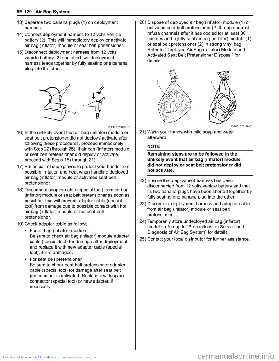
13) Separate two banana plugs (1) on deployment harness.
14) Connect deployment harness to 12 volts vehicle battery (2). This will immedi ately deploy or activate
air bag (inflator) module or seat belt pretensioner.
15) Disconnect deployment harness from 12 volts vehicle battery (2) and short two deployment
harness leads together by fully seating one banana
plug into the other.
16) In the unlikely event that air bag (inflator) module or seat belt pretensioner did not deploy / activate after
following these procedur es, proceed immediately
with Step 22) through 25). If air bag (inflator) module
or seat belt pretensioner did deploy or activate,
proceed with Steps 18) through 21).
17) Put on pair of shop gloves to protect your hands from possible irritation and heat when handling deployed
air bag (inflator) module or activated seat belt
pretensioner.
18) Disconnect adapter cable (special tool) from air bag (inflator) module or seat belt pretensioner as soon as
possible. This will preven t adapter cable (special
tool) from damage due to possible contact with hot
air bag (inflator) module or hot seat belt
pretensioner.
19) Check adapter cable as follows. • For air bag (inflator) moduleBe sure to check air bag (inflator) module adapter
cable (special tool) for damage after deployment
and replace it with new adapter cable (special
tool), if it is damaged.
• For seat belt pretensioner Be sure to check seat belt pretensioner adapter
cable (special tool) for damage after seat belt
pretensioner is activated. Replace it with spare
connector (special tool) or new adapter, if
necessary. 20) Dispose of deployed air bag (inflator) module (1) or
activated seat belt preten sioner (2) through normal
refuse channels after it has cooled for at least 30
minutes and tightly seal air bag (inflator) module (1)
or seat belt pretensioner (2) in strong vinyl bag.
Refer to “Deployed Air B ag (Inflator) Module and
Activated Seat Belt Pretensioner Disposal” for
details.
21) Wash your hands with mild soap and water afterward.
NOTE
Remaining steps are to be followed in the
unlikely event that air bag (inflator) module
did not deploy or seat belt pretensioner did
not activate.
22) Ensure that deployment harness has been disconnected from 12 volts vehicle battery and that
its two banana plugs have been shorted together by
fully seating one banana plug into the other.
23) Disconnect deployment harness and adapter cable from air bag (inflator) module or seat belt
pretensioner.
24) Temporarily store undeployed air bag (inflator) module referring to “Precautions on Service and
Diagnosis of Air Bag System” for details.
25) Contact your local distributor for further assistance.
I2RH01820069-01I3JA01820116-01
Page 1162 of 1496
Downloaded from www.Manualslib.com manuals search engine 8B-124 Air Bag System:
21) Disconnect adapter cable (special tool) from air bag (inflator) module or seat belt pretensioner as soon as
possible. This will preven t adapter cable (special
tool) from damage due to possible contact with hot
air bag (inflator) module or hot seat belt
pretensioner.
22) Check adapter cable connector as follows. Adapter cable connector (special tool) is designed to
be reused. However it should be inspected for
damage after deployment and replaced if necessary.
23) With air bag (inflator) modules deployed and seat belt pretensioners acti vated, vehicle may be
scrapped in the same manner as non-air bag system
/ seat belt pretensioner equipped vehicle.
NOTE
Remaining steps are to be followed in the
unlikely event that air bag (inflator) module
did not deploy or seat belt pretensioner did
not activate.
24) Remove undeployed air bag (inflator) module(s) and/ or inactivated seat belt pretensioner(s) from vehicle.
For driver air bag (inflator) module, refer to “Driver
Air Bag (Inflator) Module Removal and Installation”.
For passenger air bag (inflator) module, refer to
“Passenger Air Bag (Inflator) Module Removal and
Installation”. For seat belt pretensioner, refer to
“Front Seat Belt Removal an d Installation in Section
8A”.
25) Temporarily store undeployed air bag (inflator) module referring to “Precautions on Service and
Diagnosis of Air Bag System” for details.
26) Contact your local distribu tor for further assistance.
Deployed Air Bag (Inflator) Module and
Activated Seat Belt Pretensioner Disposal
S7RS0B8206019
WARNING!
Failure to follow proper air bag (inflator)
module and seat belt pretensioner disposal
procedures can result in air bag deployment
and pretensioner activation which may cause
personal injury. The undeployed air bag
(inflator) module and the inactivated seat belt
pretensioner must not be disposed of
through normal refuse channels.
The undeployed air bag (inflator) module and
the inactivated seat belt pretensioner
contains substances that can cause severe
illness or personal injury if the sealed
container is damaged during disposal.
Deployed air bag (inflator) module and the activated seat
belt pretensioner can be disposed of through normal
refuse channels just like any other parts. For their
disposal, however, the following points should be noted.
• The air bag (inflator) module and the seat belt
pretensioner immediately after deployment / activation
is very hot. Wait for 30 minu tes to cool it off before
handling it.
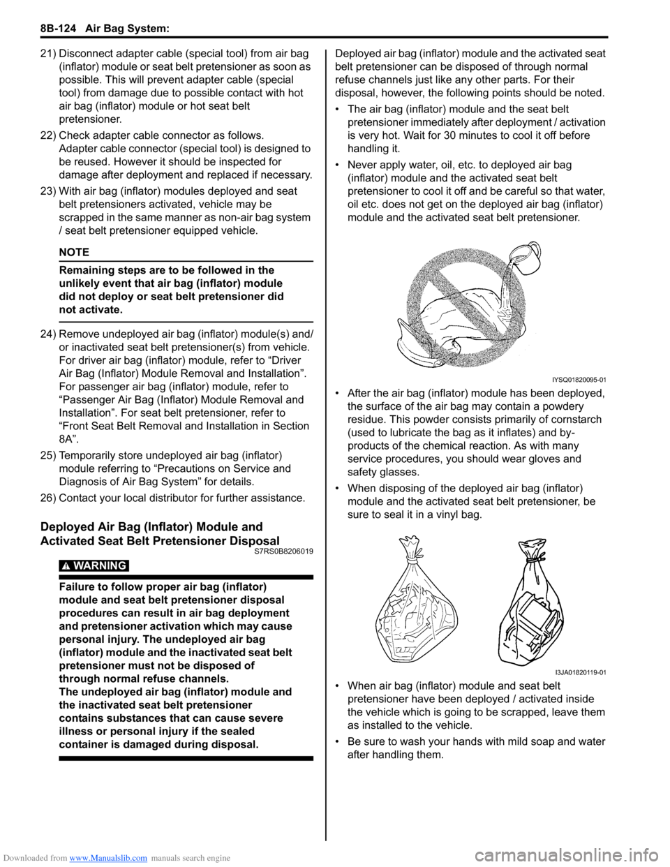
• Never apply water, oil, etc. to deployed air bag (inflator) module and the activated seat belt
pretensioner to cool it off and be careful so that water,
oil etc. does not get on the deployed air bag (inflator)
module and the activated seat belt pretensioner.
• After the air bag (inflator) module has been deployed, the surface of the air bag may contain a powdery
residue. This powder consists primarily of cornstarch
(used to lubricate the bag as it inflates) and by-
products of the chemical reaction. As with many
service procedures, you should wear gloves and
safety glasses.
• When disposing of the deployed air bag (inflator) module and the activated seat belt pretensioner, be
sure to seal it in a vinyl bag.
• When air bag (inflator) module and seat belt pretensioner have been deployed / activated inside
the vehicle which is going to be scrapped, leave them
as installed to the vehicle.
• Be sure to wash your hand s with mild soap and water
after handling them.
IYSQ01820095-01
I3JA01820119-01
Page 1179 of 1496
Downloaded from www.Manualslib.com manuals search engine Wiring Systems: 9A-8
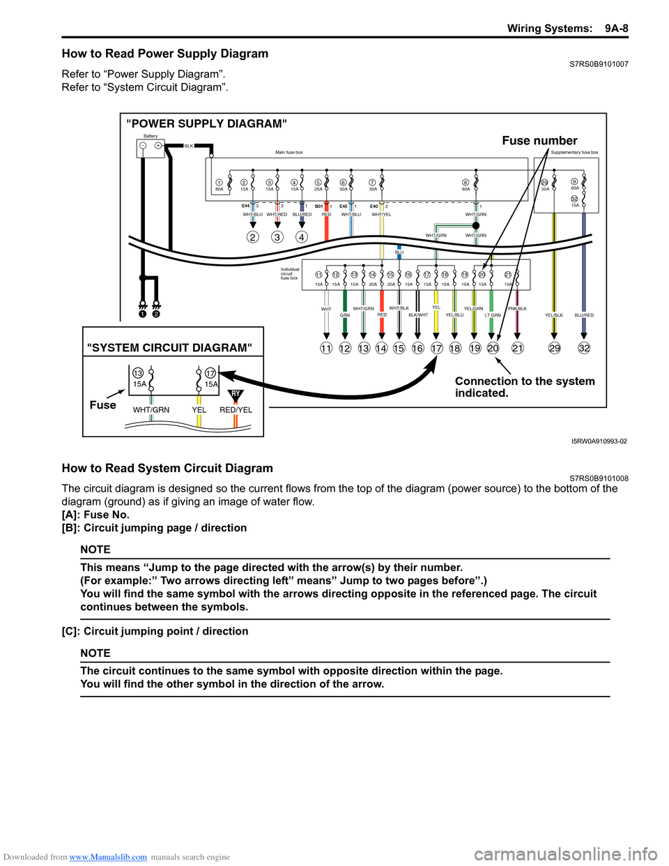
How to Read Power Supply DiagramS7RS0B9101007
Refer to “Power Supply Diagram”.
Refer to “System Circuit Diagram”.
How to Read System Circuit DiagramS7RS0B9101008
The circuit diagram is designed so the current flows from the top of the diagram (power source) to the bottom of the
diagram (ground) as if giving an image of water flow.
[A]: Fuse No.
[B]: Circuit jumping page / direction
NOTE
This means “Jump to the page directed with the arrow(s) by their number.
(For example:” Two arrows directing left” means” Jump to two pages before”.)
You will find the same symbol with the arrows directing opposite in the referenced page. The circuit
continues between the symbols.
[C]: Circuit jumping point / direction
NOTE
The circuit continues to the same symbol with opposite direction within the page.
You will find the other symbol in the direction of the arrow.
Connection to the system
indicated.
"POWER SUPPLY DIAGRAM"
-+
1
Battery
80A
215A315A415A525A67850A 30A2930A3215A
960A
60A
BLK
YEL/BLKPNK/BLKLT GRNYEL/GRNYEL/BLUBLK/WHTWHT/BLKWHT/GRNREDGRNWHT
WHT/BLUWHT/REDWHT/BLUWHT/YELWHT/GRN
WHT/GRNWHT/GRN
BLU
BLU/REDRED
YELBLU/RED
Individual
circuit
fuse box
Main fuse box
Supplementary fuse box
11
11
243
121314151617181920212932
1213141516171819202115A 15A 15A 20A 20A 15A 15A 15A 15A 15A 15A
E44
321
B011E45 1 E4021
FuseRED/YEL
YEL
WHT/GRN
15A
15A
1317
"SYSTEM CIRCUIT DIAGRAM"
Fuse number
1
2
RY
I5RW0A910993-02
Page 1295 of 1496
Downloaded from www.Manualslib.com manuals search engine Lighting Systems: 9B-13
Headlight Leveling Switch Inspection (If
Equipped)
S7RS0B9206019
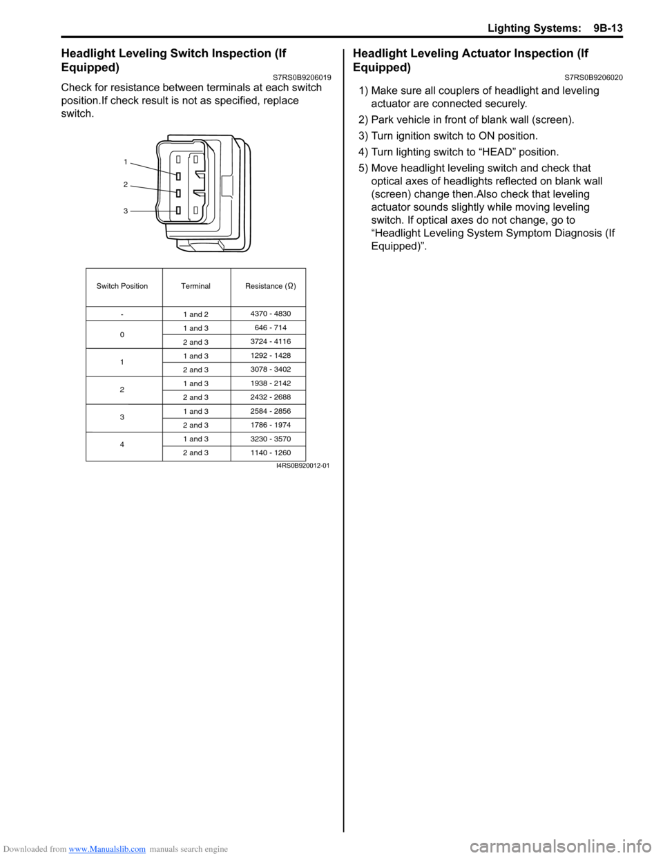
Check for resistance between terminals at each switch
position.If check result is not as specified, replace
switch.
Headlight Leveling Actuator Inspection (If
Equipped)
S7RS0B9206020
1) Make sure all couplers of headlight and leveling actuator are connected securely.
2) Park vehicle in front of blank wall (screen).
3) Turn ignition switch to ON position.
4) Turn lighting switch to “HEAD” position.
5) Move headlight leveling switch and check that
optical axes of headlights reflected on blank wall
(screen) change then.Also check that leveling
actuator sounds slightly while moving leveling
switch. If optical axes do not change, go to
“Headlight Leveling System Symptom Diagnosis (If
Equipped)”.
1
2
3
Switch Position
0 Terminal Resistance ( )
-
1
2
3
4 1 and 2
4370 - 4830
1 and 3
2 and 3
1 and 3
2 and 3
1 and 3
2 and 3
1 and 3
2 and 3
1 and 3
2 and 3 646 - 714
3724 - 4116
3078 - 3402 1292 - 1428
1938 - 2142
2584 - 2856
3230 - 3570 2432 - 2688
1786 - 1974
1140 - 1260
I4RS0B920012-01
Page 1308 of 1496
Downloaded from www.Manualslib.com manuals search engine 9C-13 Instrumentation / Driver Info. / Horn:
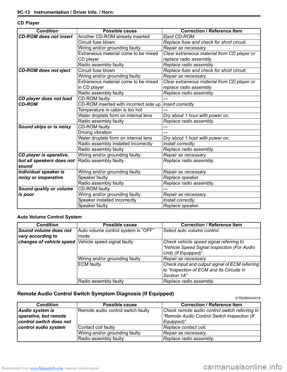
CD Player
Auto Volume Control System
Remote Audio Control Switch Symptom Diagnosis (If Equipped)S7RS0B9304018
ConditionPossible cause Correction / Reference Item
CD-ROM does not insert Another CD-ROM already inserted Eject CD-ROM.
Circuit fuse blown Replace fuse and check for short circuit.
Wiring and/or grounding faulty Repair as necessary.
Extraneous material come to be mixed
CD player Clear extraneous material from CD player or
replace radio assembly.
Radio assembly faulty Replace radio assembly.
CD-ROM does not eject Circuit fuse blown Replace fuse and check for short circuit.
Wiring and/or grounding faulty Repair as necessary.
Extraneous material come to be mixed
in CD player Clear extraneous material from CD player or
replace radio assembly.
Radio assembly faulty Replace radio assembly.
CD player does not load
CD-ROM CD-ROM faulty
—
CD-ROM inserted wit h incorrect side upInsert correctly.
Temperature in cabin is too hot —
Water droplets form on internal lens Dry about 1 hour with power on.
Radio assembly faulty Replace radio assembly.
Sound skips or is noisy CD-ROM faulty —
Driving vibration —
Water droplets form on internal lens Dry about 1 hour with power on.
Radio assembly installed incorrectly Install correctly.
Radio assembly faulty Replace radio assembly.
CD player is operative,
but all speakers does not
sound Wiring and/or grounding faulty
Repair as necessary.
Radio assembly faulty Replace radio assembly.
Individual speaker is
noisy or inoperative Wiring and/or grounding faulty
Repair as necessary.
Speaker faulty Replace speaker.
Radio assembly faulty Replace radio assembly.
Sound quality or volume
is poor CD-ROM faulty
—
Wiring and/or grounding faulty Repair as necessary.
Speaker installed incorrectly Install correctly.
Speaker faulty Replace speaker.
ConditionPossible cause Correction / Reference Item
Sound volume does not
vary according to
changes of vehicle speed Auto volume control system is “OFF”
mode
Select auto volume control.
Vehicle speed signal faulty Check vehicle speed signal referring to
“Vehicle Speed Signal Inspection (For Audio
Unit) (If Equipped)”.
Wiring and/or grounding faulty Repair as necessary.
ECM faulty Check input and output signal of ECM referring
to “Inspection of ECM and Its Circuits in
Section 1A”
Radio assembly faulty Replace radio assembly.
ConditionPossible cause Correction / Reference Item
Audio system is
operative, but remote
control switch does not
control audio system Remote audio control switch faulty
Check remote audio control switch referring to
“Remote Audio Control Switch Inspection (If
Equipped)”.
Contact coil faulty Replace contact coil.
Wiring and/or grounding faulty Repair as necessary.
Radio assembly faulty Replace radio assembly.
Page 1332 of 1496
Downloaded from www.Manualslib.com manuals search engine 9E-5 Glass / Windows / Mirrors:
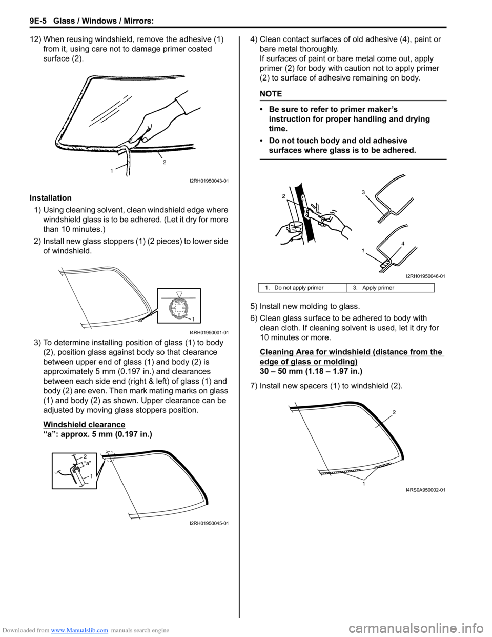
12) When reusing windshield, remove the adhesive (1) from it, using care not to damage primer coated
surface (2).
Installation 1) Using cleaning solvent, clean windshield edge where windshield glass is to be adhered. (Let it dry for more
than 10 minutes.)
2) Install new glass stoppers (1) (2 pieces) to lower side of windshield.
3) To determine installing position of glass (1) to body (2), position glass against body so that clearance
between upper end of glass (1) and body (2) is
approximately 5 mm (0.197 in.) and clearances
between each side end (right & left) of glass (1) and
body (2) are even. Then mark mating marks on glass
(1) and body (2) as shown. Upper clearance can be
adjusted by moving glass stoppers position.
Windshield clearance
“a”: approx. 5 mm (0.197 in.) 4) Clean contact surfaces of old adhesive (4), paint or
bare metal thoroughly.
If surfaces of paint or ba re metal come out, apply
primer (2) for body with caution not to apply primer
(2) to surface of adhesive remaining on body.
NOTE
• Be sure to refer to primer maker’s instruction for proper handling and drying
time.
• Do not touch body and old adhesive surfaces where glass is to be adhered.
5) Install new molding to glass.
6) Clean glass surface to be adhered to body with clean cloth. If cleaning solvent is used, let it dry for
10 minutes or more.
Cleaning Area for windshie ld (distance from the
edge of glass or molding)
30 – 50 mm (1.18 – 1.97 in.)
7) Install new spacers (1) to windshield (2).
I2RH01950043-01
1
I4RH01950001-01
2
1“a”
I2RH01950045-01
1. Do not apply primer 3. Apply primer
I2RH01950046-01
2
1I4RS0A950002-01