disc SUZUKI SWIFT 2006 2.G Service Workshop Manual
[x] Cancel search | Manufacturer: SUZUKI, Model Year: 2006, Model line: SWIFT, Model: SUZUKI SWIFT 2006 2.GPages: 1496, PDF Size: 34.44 MB
Page 560 of 1496
Downloaded from www.Manualslib.com manuals search engine 4E-21 ABS:
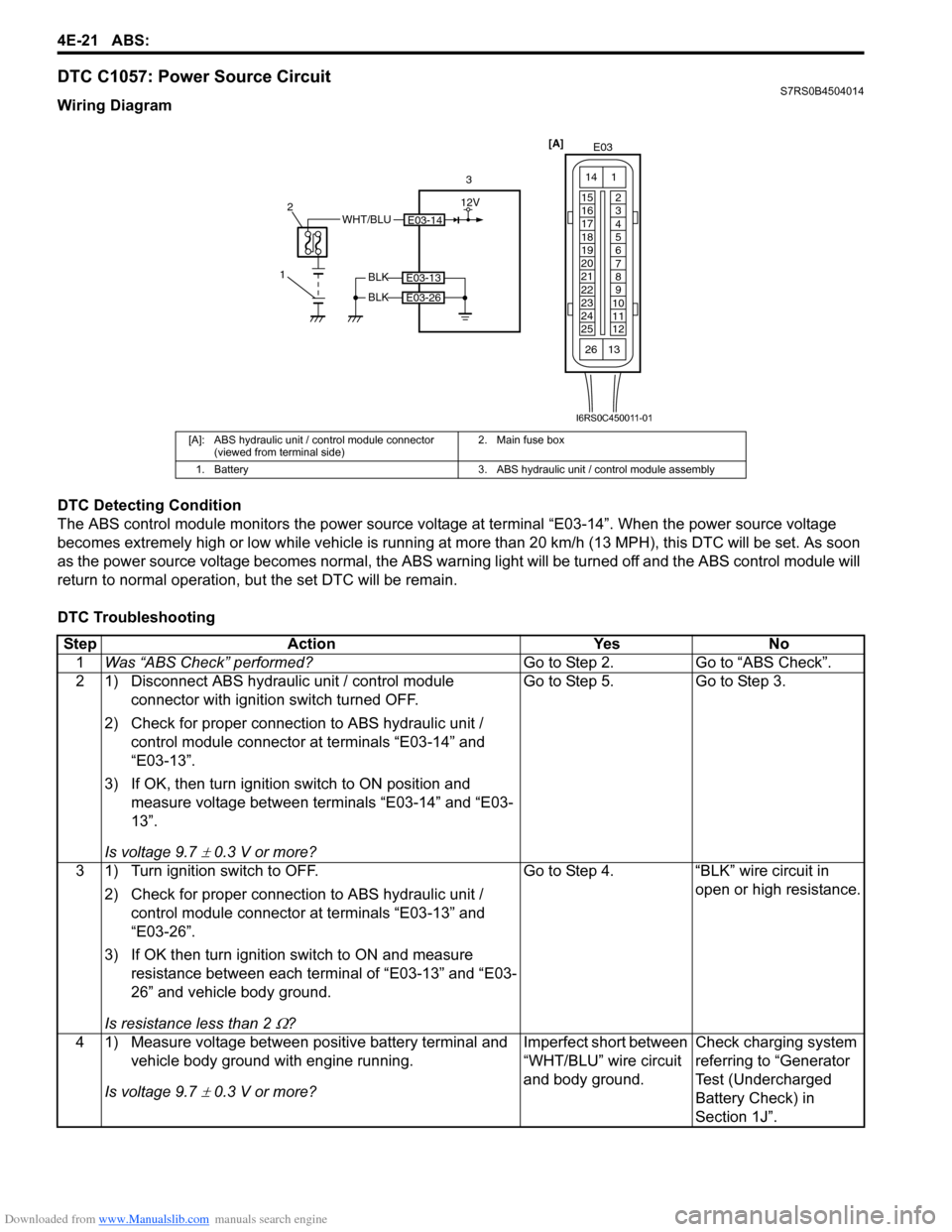
DTC C1057: Power Source CircuitS7RS0B4504014
Wiring Diagram
DTC Detecting Condition
The ABS control module monitors the power source voltage at terminal “E03-14”. When the power source voltage
becomes extremely high or low while vehicle is running at more than 20 km/h (13 MPH), this DTC will be set. As soon
as the power source volta ge becomes normal, the ABS warning light will be turned off and the ABS control module will
return to normal operation, bu t the set DTC will be remain.
DTC Troubleshooting
[A]: ABS hydraulic unit / control module connector (viewed from terminal side) 2. Main fuse box
1. Battery 3. ABS hydraulic unit / control module assembly
E03-14WHT/BLU
1 2
3
BLK
BLK
E03-13
E03-26
[A]
E03
15
16
17
18
19
20
21
22
23
24
25 2
3
4
5
6
7
8
9
10
11
12
1
13
14
26
12V
I6RS0C450011-01
Step
Action YesNo
1 Was “ABS Check” performed? Go to Step 2.Go to “ABS Check”.
2 1) Disconnect ABS hydraulic unit / control module connector with ignition switch turned OFF.
2) Check for proper connection to ABS hydraulic unit / control module connector at terminals “E03-14” and
“E03-13”.
3) If OK, then turn ignition switch to ON position and measure voltage between terminals “E03-14” and “E03-
13”.
Is voltage 9.7
± 0.3 V or more? Go to Step 5. Go to Step 3.
3 1) Turn ignition switch to OFF. 2) Check for proper connection to ABS hydraulic unit / control module connector at terminals “E03-13” and
“E03-26”.
3) If OK then turn ignition switch to ON and measure resistance between each terminal of “E03-13” and “E03-
26” and vehicle body ground.
Is resistance less than 2
Ω? Go to Step 4. “BLK” wire circuit in
open or high resistance.
4 1) Measure voltage between positive battery terminal and vehicle body ground with engine running.
Is voltage 9.7
± 0.3 V or more? Imperfect short between
“WHT/BLU” wire circuit
and body ground.
Check charging system
referring to “Generator
Test (Undercharged
Battery Check) in
Section 1J”.
Page 561 of 1496
Downloaded from www.Manualslib.com manuals search engine ABS: 4E-22
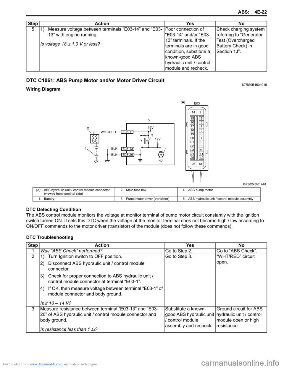
DTC C1061: ABS Pump Motor and/or Motor Driver CircuitS7RS0B4504015
Wiring Diagram
DTC Detecting Condition
The ABS control module monitors the voltage at monitor terminal of pump motor circuit constantly with the ignition
switch turned ON. It sets this DTC when the voltage at the monitor terminal does not become high / low according to
ON/OFF commands to the motor driver (transistor) of the module (does not follow these commands).
DTC Troubleshooting 5 1) Measure voltage between terminals “E03-14” and “E03-
13” with engine running.
Is voltage 18
± 1.0 V or less? Poor connection of
“E03-14” and/or “E03-
13” terminals. If the
terminals are in good
condition, substitute a
known-good ABS
hydraulic unit / control
module and recheck.Check charging system
referring to “Generator
Test (Overcharged
Battery Check) in
Section 1J”.
Step Action Yes No
WHT/RED
1 2
5
BLK
BLK
E03-13
E03-26
[A]
E03
15
16
17
18
19
20
21
22
23
24
25 2
3
4
5
6
7
8
9
10
11
12
1
13
14
26
M
3
4E03-1
12V
12V
I6RS0C450012-01
[A]: ABS hydraulic unit / control module connector (viewed from terminal side) 2. Main fuse box 4. ABS pump motor
1. Battery 3. Pump motor driver (transistor) 5. ABS hydraulic unit / control module assembly
StepAction YesNo
1 Was “ABS Check” performed? Go to Step 2.Go to “ABS Check”.
2 1) Turn Ignition switch to OFF position.
2) Disconnect ABS hydraulic unit / control module connector.
3) Check for proper connection to ABS hydraulic unit / control module connector at terminal “E03-1”.
4) If OK, then measure voltage between terminal “E03-1” of module connector and body ground.
Is it 10 – 14 V? Go to Step 3.
“WHT/RED” circuit
open.
3 Measure resistance between terminal “E03-13” and “E03- 26” of ABS hydraulic unit / co ntrol module connector and
body ground.
Is resistance less than 1
Ω? Substitute a known-
good ABS hydraulic unit
/ control module
assembly and recheck.
Ground circuit for ABS
hydraulic unit / control
module open or high
resistance.
Page 562 of 1496
Downloaded from www.Manualslib.com manuals search engine 4E-23 ABS:
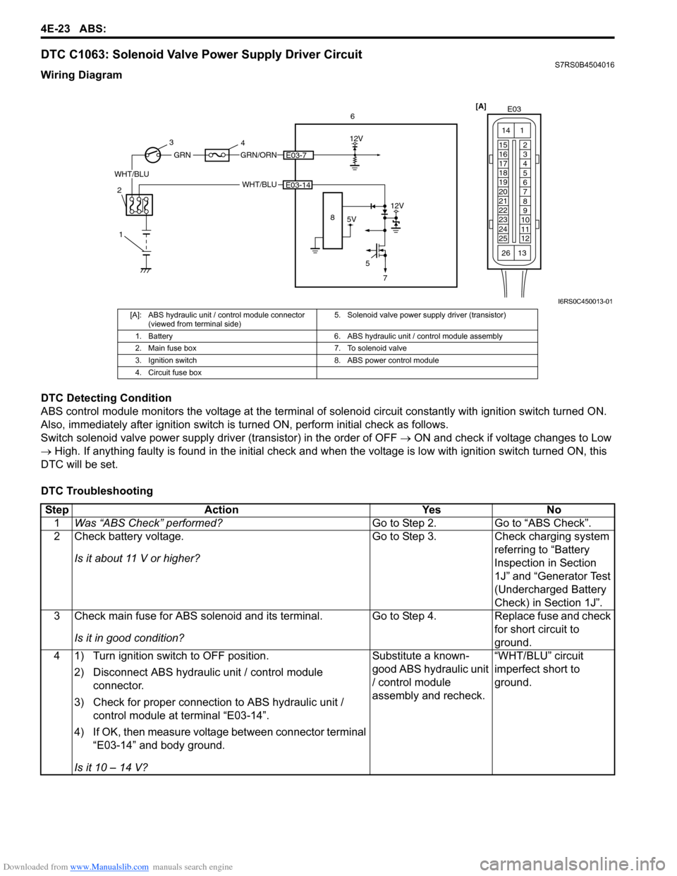
DTC C1063: Solenoid Valve Power Supply Driver CircuitS7RS0B4504016
Wiring Diagram
DTC Detecting Condition
ABS control module monitors the voltage at the terminal of solenoid circuit constantly with ignition switch turned ON.
Also, immediately after ignition switch is turned ON, perform initial check as follows.
Switch solenoid valve power supply driv er (transistor) in the order of OFF → ON and check if voltage changes to Low
→ High. If anything faulty is found in the initial check and when the voltage is low with ignition switch turned ON, this
DTC will be set.
DTC Troubleshooting
[A] E03
15
16
17
18
19
20
21
22
23
24
25 2
3
4
5
6
7
8
9
10
11
12
1
13
14
266
WHT/BLU
12V
5E03-14
5V
12V
8
GRN/ORNE03-7
WHT/BLU
GRN
1
2 3
4
7
I6RS0C450013-01
[A]: ABS hydraulic unit / control module connector
(viewed from terminal side) 5. Solenoid valve power supp
ly driver (transistor)
1. Battery 6. ABS hydraulic unit / control module assembly
2. Main fuse box 7. To solenoid valve
3. Ignition switch 8. ABS power control module
4. Circuit fuse box
Step Action YesNo
1 Was “ABS Check” performed? Go to Step 2.Go to “ABS Check”.
2 Check battery voltage.
Is it about 11 V or higher? Go to Step 3.
Check charging system
referring to “Battery
Inspection in Section
1J” and “Generator Test
(Undercharged Battery
Check) in Section 1J”.
3 Check main fuse for ABS solenoid and its terminal.
Is it in good condition? Go to Step 4.
Replace fuse and check
for short circuit to
ground.
4 1) Turn ignition switch to OFF position.
2) Disconnect ABS hydraulic unit / control module connector.
3) Check for proper connection to ABS hydraulic unit / control module at terminal “E03-14”.
4) If OK, then measure voltage between connector terminal “E03-14” and body ground.
Is it 10 – 14 V? Substitute a known-
good ABS hydraulic unit
/ control module
assembly and recheck.
“WHT/BLU” circuit
imperfect short to
ground.
Page 563 of 1496
Downloaded from www.Manualslib.com manuals search engine ABS: 4E-24
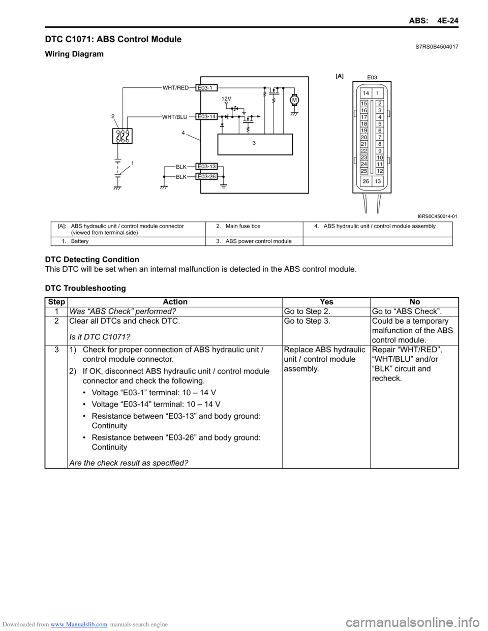
DTC C1071: ABS Control ModuleS7RS0B4504017
Wiring Diagram
DTC Detecting Condition
This DTC will be set when an internal malfunction is detected in the ABS control module.
DTC Troubleshooting
1
2
WHT/RED
12VM
3
4
E03-1
E03-14
BLK
BLK
E03-13
E03-26
WHT/BLU [A]
E03
15
16
17
18
19
20
21
22
23
24
25 2
3
4
5
6
7
8
9
10
11
12
1
13
14
26
I6RS0C450014-01
[A]: ABS hydraulic unit / control module connector
(viewed from terminal side) 2. Main fuse box 4. ABS hydraulic unit / control module assembly
1. Battery 3. ABS power control module
Step Action YesNo
1 Was “ABS Check” performed? Go to Step 2.Go to “ABS Check”.
2 Clear all DTCs and check DTC.
Is it DTC C1071? Go to Step 3.
Could be a temporary
malfunction of the ABS
control module.
3 1) Check for proper connection of ABS hydraulic unit / control module connector.
2) If OK, disconnect ABS hydr aulic unit / control module
connector and check the following.
• Voltage “E03-1” terminal: 10 – 14 V
• Voltage “E03-14” terminal: 10 – 14 V
• Resistance between “E03-13” and body ground: Continuity
• Resistance between “E03-26” and body ground: Continuity
Are the check result as specified? Replace ABS hydraulic
unit / control module
assembly.
Repair “WHT/RED”,
“WHT/BLU” and/or
“BLK” circuit and
recheck.
Page 565 of 1496
Downloaded from www.Manualslib.com manuals search engine ABS: 4E-26
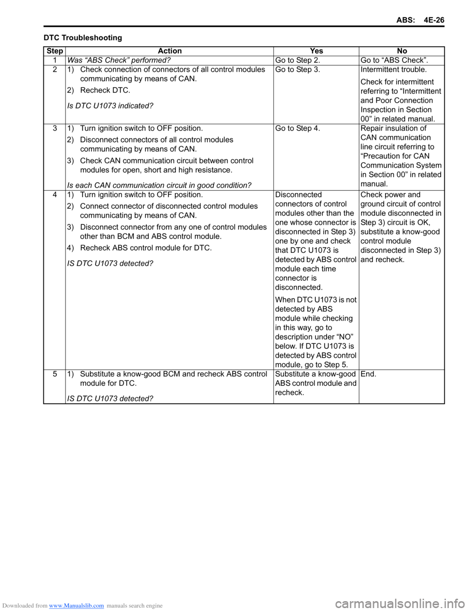
DTC TroubleshootingStep Action Yes No 1 Was “ABS Check” performed? Go to Step 2. Go to “ABS Check”.
2 1) Check connection of connectors of all control modules communicating by means of CAN.
2) Recheck DTC.
Is DTC U1073 indicated? Go to Step 3. Intermittent trouble.
Check for intermittent
referring to “Intermittent
and Poor Connection
Inspection in Section
00” in related manual.
3 1) Turn ignition switch to OFF position.
2) Disconnect connectors of all control modules communicating by means of CAN.
3) Check CAN communication circuit between control modules for open, short and high resistance.
Is each CAN communication circuit in good condition? Go to Step 4. Repair insulation of
CAN communication
line circuit referring to
“Precaution for CAN
Communication System
in Section 00” in related
manual.
4 1) Turn ignition switch to OFF position.
2) Connect connector of disconnected control modules communicating by means of CAN.
3) Disconnect connector from any one of control modules other than BCM and ABS control module.
4) Recheck ABS contro l module for DTC.
IS DTC U1073 detected? Disconnected
connectors of control
modules other than the
one whose connector is
disconnected in Step 3)
one by one and check
that DTC U1073 is
detected by ABS control
module each time
connector is
disconnected.
When DTC U1073 is not
detected by ABS
module while checking
in this way, go to
description under “NO”
below. If DTC U1073 is
detected by ABS control
module, go to Step 5.Check power and
ground circuit of control
module disconnected in
Step 3) circuit is OK,
substitute a know-good
control module
disconnected in Step 3)
and recheck.
5 1) Substitute a know-good BCM and recheck ABS control module for DTC.
IS DTC U1073 detected? Substitute a know-good
ABS control module and
recheck.
End.
Page 566 of 1496
Downloaded from www.Manualslib.com manuals search engine 4E-27 ABS:
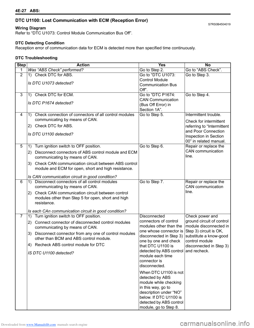
DTC U1100: Lost Communication with ECM (Reception Error)S7RS0B4504019
Wiring Diagram
Refer to “DTC U1073: Control Module Communication Bus Off”.
DTC Detecting Condition
Reception error of communication data for ECM is detected more than specified time continuously.
DTC Troubleshooting Step Action Yes No 1 Was “ABS Check” performed? Go to Step 2. Go to “ABS Check”.
2 1) Check DTC for ABS.
Is DTC U1073 detected? Go to “DTC U1073:
Control Module
Communication Bus
Off”.Go to Step 3.
3 1) Check DTC for ECM. Is DTC P1674 detected? Go to “DTC P1674:
CAN Communication
(Bus Off Error) in
Section 1A”.Go to Step 4.
4 1) Check connection of connectors of all control modules communicating by means of CAN.
2) Check DTC for ABS.
Is DTC U1100 detected? Go to Step 5. Intermittent trouble.
Check for intermittent
referring to “Intermittent
and Poor Connection
Inspection in Section
00” in related manual.
5 1) Turn ignition switch to OFF position.
2) Disconnect connectors of ABS control module and ECM
communicating by means of CAN.
3) Check CAN communication circuit between ABS control module and ECM for open, short and high resistance.
Is CAN communication circuit in good condition? Go to Step 6. Repair or replace the
CAN communication
line.
6 1) Disconnect connectors of all control modules communicating by means of CAN.
2) Check CAN communication circuit between control modules other than Step 5 for open, short and high
resistance.
Is each CAn communication circuit in good condition? Go to Step 7. Repair or replace the
CAN communication
line.
7 1) Turn ignition switch to OFF position. 2) Connect connector of disconnected control modules communicating by means of CAN.
3) Disconnect connector from any one of control modules other than BCM and ABS control module.
4) Recheck ABS contro l module for DTC
IS DTC U1100 detected? Disconnected
connectors of control
modules other than the
one whose connector is
disconnected in Step 3)
one by one and check
that DTC U1100 is
detected by ABS control
module each time
connector is
disconnected.
When DTC U1100 is not
detected by ABS
module while checking
in this way, go to
description under “NO”
below. If DTC U1100 is
detected by ABS control
module, go to Step 8.Check power and
ground circuit of control
module disconnected in
Step 3) circuit is OK,
substitute a know-good
control module
disconnected in Step 3)
and recheck.
Page 567 of 1496
Downloaded from www.Manualslib.com manuals search engine ABS: 4E-28
Repair Instructions
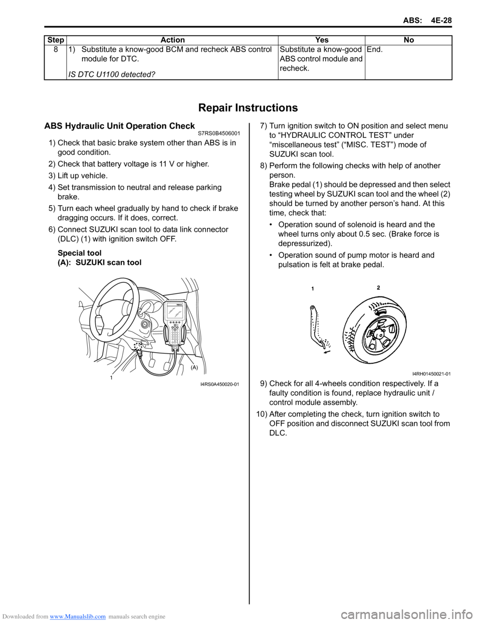
ABS Hydraulic Unit Operation CheckS7RS0B4506001
1) Check that basic brake system other than ABS is in good condition.
2) Check that battery voltage is 11 V or higher.
3) Lift up vehicle.
4) Set transmission to neutral and release parking brake.
5) Turn each wheel gradually by hand to check if brake dragging occurs. If it does, correct.
6) Connect SUZUKI scan tool to data link connector (DLC) (1) with ignition switch OFF.
Special tool
(A): SUZUKI scan tool 7) Turn ignition switch to ON position and select menu
to “HYDRAULIC CONTROL TEST” under
“miscellaneous test” (“MISC. TEST”) mode of
SUZUKI scan tool.
8) Perform the following checks with help of another person.
Brake pedal (1) should be depressed and then select
testing wheel by SUZUKI scan tool and the wheel (2)
should be turned by another person’s hand. At this
time, check that:
• Operation sound of solenoid is heard and the wheel turns only about 0.5 sec. (Brake force is
depressurized).
• Operation sound of pump motor is heard and pulsation is felt at brake pedal.
9) Check for all 4-wheels co ndition respectively. If a
faulty condition is found, replace hydraulic unit /
control module assembly.
10) After completing the check, turn ignition switch to OFF position and disconnect SUZUKI scan tool from
DLC.
8 1) Substitute a know-good BCM and recheck ABS control
module for DTC.
IS DTC U1100 detected? Substitute a know-good
ABS control module and
recheck.
End.
Step Action Yes No
1 (A)I4RS0A450020-01
I4RH01450021-01
Page 568 of 1496
Downloaded from www.Manualslib.com manuals search engine 4E-29 ABS:
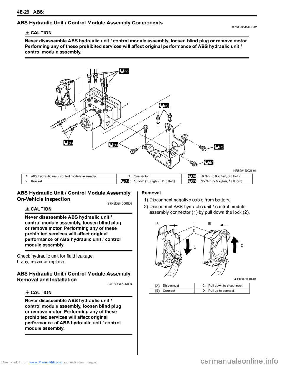
ABS Hydraulic Unit / Control Module Assembly ComponentsS7RS0B4506002
CAUTION!
Never disassemble ABS hydraulic unit / control module assembly, loosen blind plug or remove motor.
Performing any of these prohibited services will affect original performance of ABS hydraulic unit /
control module assembly.
ABS Hydraulic Unit / Control Module Assembly
On-Vehicle Inspection
S7RS0B4506003
CAUTION!
Never disassemble ABS hydraulic unit /
control module assembly, loosen blind plug
or remove motor. Pe rforming any of these
prohibited services wi ll affect original
performance of ABS hydraulic unit / control
module assembly.
Check hydraulic unit for fluid leakage.
If any, repair or replace.
ABS Hydraulic Unit / Control Module Assembly
Removal and Installation
S7RS0B4506004
CAUTION!
Never disassemble ABS hydraulic unit /
control module assembly, loosen blind plug
or remove motor. Pe rforming any of these
prohibited services wi ll affect original
performance of ABS hydraulic unit / control
module assembly.
Removal
1) Disconnect negative cable from battery.
2) Disconnect ABS hydraulic unit / control module assembly connector (1) by pull down the lock (2).
(a)
(a)
(b)
(b)
(c)(c)
1
2
3
I4RS0A450021-01
1. ABS hydraulic unit / control module assembly
3. Connector: 9 N⋅m (0.9 kgf-m, 6.5 lb-ft)
2. Bracket : 16 N⋅m (1.6 kgf-m, 11.5 lb-ft) : 25 N⋅m (2.5 kgf-m, 18.0 lb-ft)
[A]: Disconnect C: Pull down to disconnect
[B]: Connect D: Pull up to connect
21
C D
[A]
[B]
I4RH01450001-01
Page 569 of 1496
Downloaded from www.Manualslib.com manuals search engine ABS: 4E-30
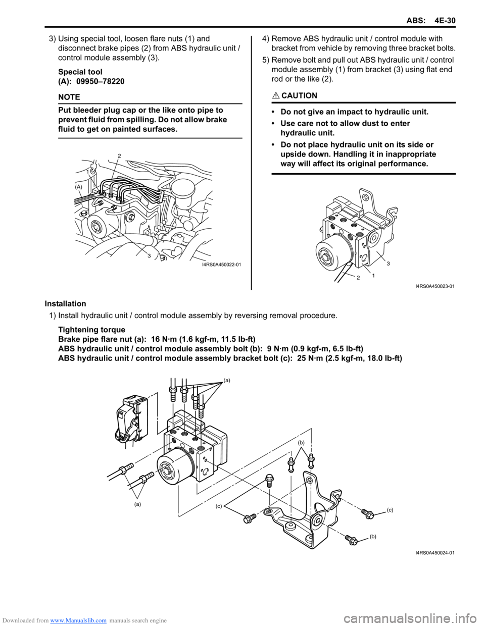
3) Using special tool, loosen flare nuts (1) and disconnect brake pipes (2) from ABS hydraulic unit /
control module assembly (3).
Special tool
(A): 09950–78220
NOTE
Put bleeder plug cap or the like onto pipe to
prevent fluid from spilli ng. Do not allow brake
fluid to get on painted surfaces.
4) Remove ABS hydraulic unit / control module with
bracket from vehicle by removing three bracket bolts.
5) Remove bolt and pull out ABS hydraulic unit / control module assembly (1) from bracket (3) using flat end
rod or the like (2).
CAUTION!
• Do not give an impact to hydraulic unit.
• Use care not to allow dust to enter hydraulic unit.
• Do not place hydraulic unit on its side or upside down. Handling it in inappropriate
way will affect its original performance.
Installation
1) Install hydraulic unit / control module assembly by reversing removal procedure.
Tightening torque
Brake pipe flare nut (a): 16 N·m (1.6 kgf-m, 11.5 lb-ft)
ABS hydraulic unit / control module assembly bolt (b): 9 N·m (0.9 kgf-m, 6.5 lb-ft)
ABS hydraulic unit / control module assembly bracket bolt (c): 25 N·m (2.5 kgf-m, 18.0 lb-ft)
3
2
1
(A)
I4RS0A450022-01
1
3
2
I4RS0A450023-01
(a) (a)(c)
(c)
(b)
(b)
I4RS0A450024-01
Page 570 of 1496
Downloaded from www.Manualslib.com manuals search engine 4E-31 ABS:
2) Bleed air from brake system referring to “Air Bleeding of Brake System in Section 4A”.
3) Check each installed part for fluid leakage and perform “ABS Hydraulic Un it Operation Check”.
NOTE
For new ABS hydraulic unit / control module
assembly, if “ABS Hydraulic Unit Operation
Check” has not been performed, ABS
warning light may flash when ignition switch
is turned ON position.
Accordingly preform “ABS Hydraulic Unit
Operation Check” to stop flashing of ABS
warning light.
Front / Rear Wheel Speed Sensor On-Vehicle
Inspection
S7RS0B4506005
Output Voltage Inspection
1) Disconnect negative cable from battery.
2) Hoist vehicle a little.
3) Disconnect wheel speed sensor connector.
4) Disconnect wheel speed grommet from vehicle body.
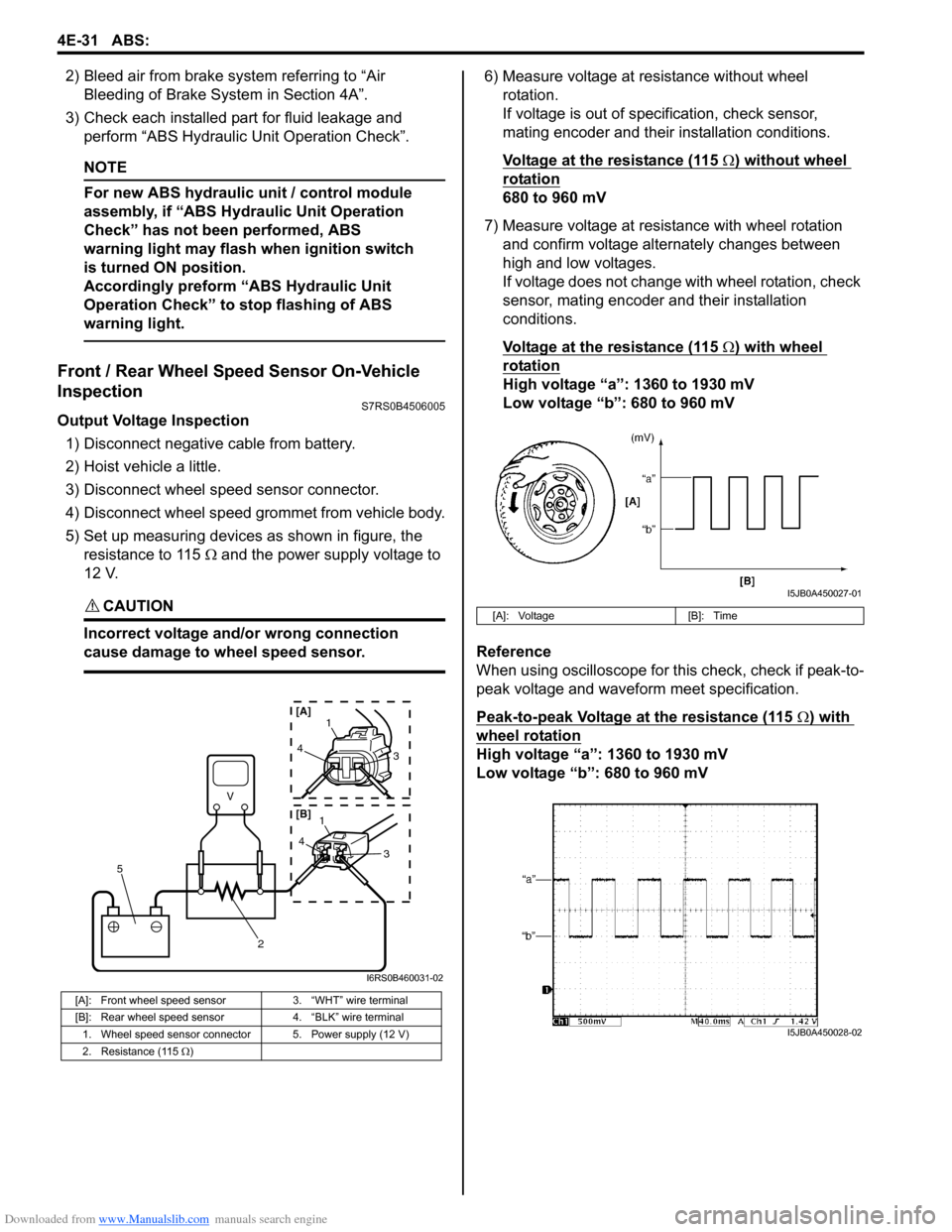
5) Set up measuring devices as shown in figure, the resistance to 115 Ω and the power supply voltage to
12 V.
CAUTION!
Incorrect voltage and/or wrong connection
cause damage to wheel speed sensor.
6) Measure voltage at resistance without wheel rotation.
If voltage is out of specification, check sensor,
mating encoder and their installation conditions.
Voltage at the resistance (115
Ω) without wheel
rotation
680 to 960 mV
7) Measure voltage at resistance with wheel rotation and confirm voltage alternately changes between
high and low voltages.
If voltage does not change with wheel rotation, check
sensor, mating encoder and their installation
conditions.
Voltage at the resistance (115
Ω) with wheel
rotation
High voltage “a”: 1360 to 1930 mV
Low voltage “b”: 680 to 960 mV
Reference
When using oscilloscope for this check, check if peak-to-
peak voltage and waveform meet specification.
Peak-to-peak Voltage at the resistance (115
Ω) with
wheel rotation
High voltage “a”: 1360 to 1930 mV
Low voltage “b”: 680 to 960 mV
[A]: Front wheel speed sensor 3. “WHT” wire terminal
[B]: Rear wheel speed sensor 4. “BLK” wire terminal
1. Wheel speed sensor connector 5. Power supply (12 V)
2. Resistance (115 Ω )
V
2
5
41
3
43
1
[A]
[B]
I6RS0B460031-02
[A]: Voltage [B]: Time
I5JB0A450027-01
I5JB0A450028-02