101 SUZUKI SWIFT 2006 2.G Service Owner's Manual
[x] Cancel search | Manufacturer: SUZUKI, Model Year: 2006, Model line: SWIFT, Model: SUZUKI SWIFT 2006 2.GPages: 1496, PDF Size: 34.44 MB
Page 57 of 1496
Downloaded from www.Manualslib.com manuals search engine Engine General Information and Diagnosis: 1A-7
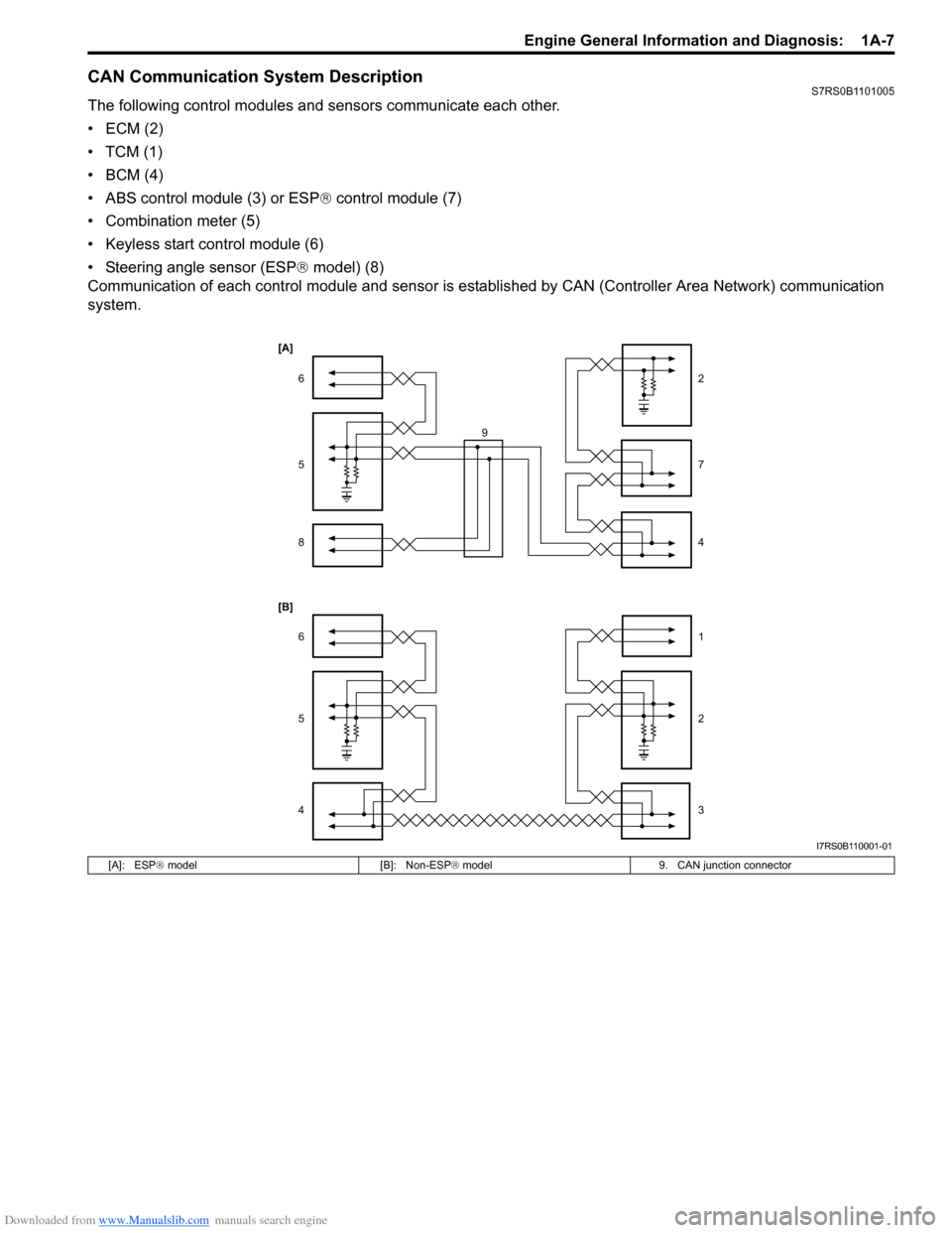
CAN Communication System DescriptionS7RS0B1101005
The following control modules and sensors communicate each other.
•ECM (2)
•TCM (1)
•BCM (4)
• ABS control module (3) or ESP® control module (7)
• Combination meter (5)
• Keyless start control module (6)
• Steering angle sensor (ESP ® model) (8)
Communication of each control module and sensor is es tablished by CAN (Controller Area Network) communication
system.
1
2
3
6
5
4
2
7
4
6
5
8
9
[A]
[B]
I7RS0B110001-01
[A]: ESP
® model [B]: Non-ESP ® model 9. CAN junction connector
Page 59 of 1496
Downloaded from www.Manualslib.com manuals search engine Engine General Information and Diagnosis: 1A-9
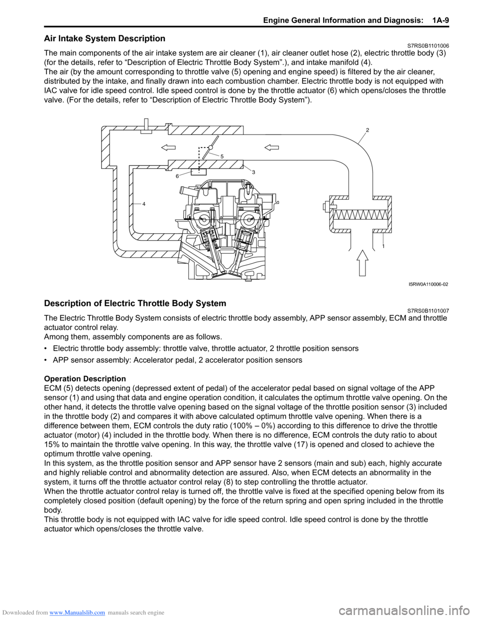
Air Intake System DescriptionS7RS0B1101006
The main components of the air intake system are air cleaner (1), air cleaner outlet hose (2), electric throttle body (3)
(for the details, refer to “Description of Electric Throttle Body System”.), and intake manifold (4).
The air (by the amount corresponding to throttle valve (5) opening and engine speed) is filtered by the air cleaner,
distributed by the intake, and finally drawn into each combusti on chamber. Electric throttle body is not equipped with
IAC valve for idle speed control. Idle speed control is done by the throttle actuator (6) which opens/closes the throttle
valve. (For the details, refer to “Description of Electric Throttle Body System”).
Description of Electric Throttle Body SystemS7RS0B1101007
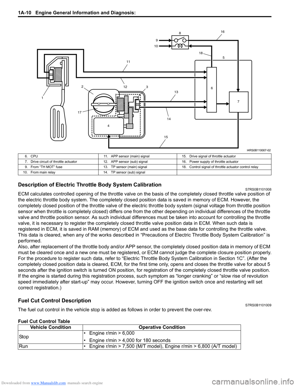
The Electric Throttle Body System consists of electric throttle body asse mbly, APP sensor assembly, ECM and throttle
actuator control relay.
Among them, assembly components are as follows.
• Electric throttle body assembly: throttle valve, throttle actuator, 2 throttle position sensors
• APP sensor assembly: Accelerator pe dal, 2 accelerator position sensors
Operation Description
ECM (5) detects opening (depressed extent of pedal) of the accelerator pedal based on signal voltage of the APP
sensor (1) and using that data and engi ne operation condition, it calculates the optimum throttle valve opening. On the
other hand, it detects the throttle valve opening based on the signal voltage of the throttle position sensor (3) included
in the throttle body (2) and compares it with above calculated optimum throttle valve opening. When there is a
difference between them, ECM controls the duty ratio (100% – 0%) according to this difference to drive the throttle
actuator (motor) (4) included in the throttle body. When th ere is no difference, ECM controls the duty ratio to about
15% to maintain the throttle valve opening . In this way, the throttle valve (17) is opened and closed to achieve the
optimum throttle valve opening.
In this system, as the thrott le position sensor and APP sensor have 2 sensors (main and sub) each, highly accurate
and highly reliable control and abnormality detection are assured. Also, when ECM detects an abnormality in the
system, it turns off the th rottle actuator control relay (8) to step controlling the throttle actuator.
When the throttle actuator control relay is turned off, the throttle valve is fixed at the specified opening below from its
completely closed position (default openin g) by the force of the return spring and open spring included in the throttle
body.
This throttle body is not equipped with IAC valve for idle speed control. Idle speed control is done by the throttle
actuator which opens/closes the throttle valve.
4 2
1
3
5
6
I5RW0A110006-02
Page 60 of 1496
Downloaded from www.Manualslib.com manuals search engine 1A-10 Engine General Information and Diagnosis:
Description of Electric Throttle Body System CalibrationS7RS0B1101008
ECM calculates controlled opening of the throttle valve on the basis of the completely closed throttle valve position of
the electric throttle body system. The completely closed position data is saved in memory of ECM. However, the
completely closed position of the throttle valve of the electric throttle body system (signal voltage from throttle position
sensor when throttle is completely closed) differs one from the other depending on individual differences of the throttle
valve and throttle position sensor. As such individual diff erences must be taken into account for controlling the throttle
valve, it is necessary to register the completely closed throttle valve position data in ECM. When such data is
registered in ECM, it is sa ved in RAM (memory) of ECM and used as the base data for controlling the throttle valve.
This data is cleared, when any of the works described in “Preca utions of Electric Throttle Body System Calibration” is
performed.
Also, after replacement of the throttle body and/or APP sensor , the completely closed position data in memory of ECM
must be cleared once and a new one must be registered, or ECM cannot judge the complete closure position properly.
For the procedure to register such data, refer to “Electric Throttle Body System Calibration in Section 1C”. (After the
completely closed position data is cleared , ECM, for the first time only, opens and closes the throttle valve for about 5
seconds after the ignition switch is turned ON position, for re gistration of the completely closed throttle valve position.
If the engine is started during this registration process, such symptom as “longe r cranking” or “slow rise of revolution
speed immediately after start-up” may occur. However, turning OFF the ignition switch once and restarting will set
correct registration.)
Fuel Cut Control DescriptionS7RS0B1101009
The fuel cut control in the vehicle stop is add ed as follows in order to prevent the over-rev.
Fuel Cut Control Table
4
1
2
17 3 5
6 7
8
9
10
11
12 13
14
15 16
18
I4RS0B110007-02
6. CPU 11. APP sensor (main) signal15. Drive signal of throttle actuator
7. Drive circuit of throttle actuator 12. APP sensor (sub) signal 16. Power supply of throttle actuator
9. From “TH MOT” fuse 13. TP sensor (main) signal 18. Control signal of throttle actuator control relay
10. From main relay 14. TP sensor (sub) signal
Vehicle ConditionOperative Condition
Sto p • Engine r/min > 6,000
• Engine r/min > 4,000 for 180 seconds
Run • Engine r/min > 7,500 (M/T model), Engine r/min > 6,800 (A/T model)
Page 61 of 1496
Downloaded from www.Manualslib.com manuals search engine Engine General Information and Diagnosis: 1A-11
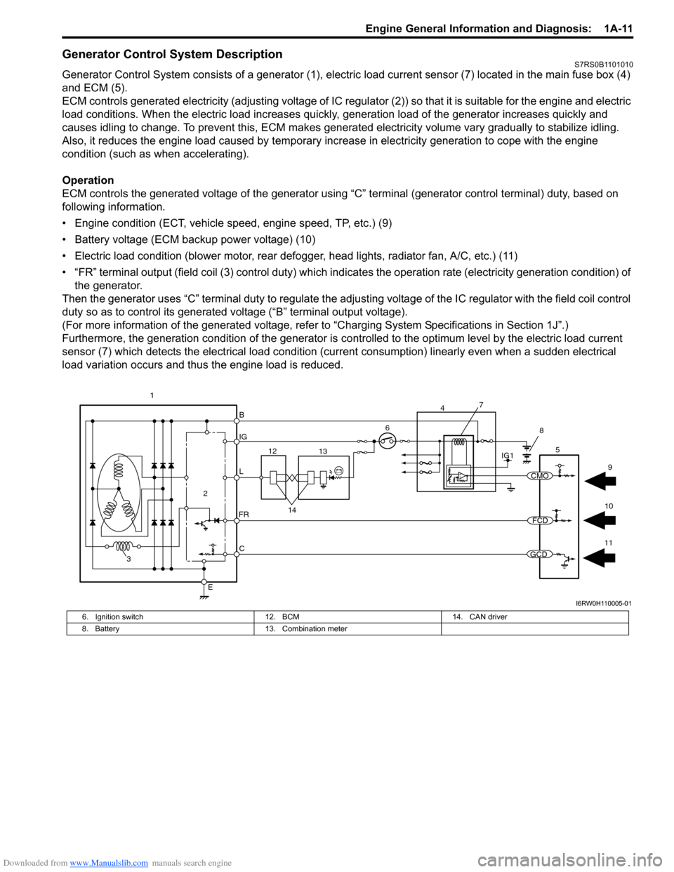
Generator Control System DescriptionS7RS0B1101010
Generator Control System consists of a generator (1), electric load current sensor (7) located in the main fuse box (4)
and ECM (5).
ECM controls generated electricity (adjusting voltage of IC regulator (2)) so that it is suitable for the engine and electric
load conditions. When the electric load increases quickly, generation load of the generator increases quickly and
causes idling to change. To prevent this, ECM makes generated electricity volume vary gradually to stabilize idling.
Also, it reduces the engine load caused by temporary incr ease in electricity generation to cope with the engine
condition (such as when accelerating).
Operation
ECM controls the generated voltage of the generator using “C” terminal (generator control terminal) duty, based on
following information.
• Engine condition (ECT, vehicle speed, engine speed, TP, etc.) (9)
• Battery voltage (ECM backup power voltage) (10)
• Electric load condition (blower motor, rear defogger, head lights, radiator fan, A/C, etc.) (11)
• “FR” terminal output (field coil (3) cont rol duty) which indicates the operation rate (electricity generation condition) of
the generator.
Then the generator uses “C” terminal duty to regulate the adju sting voltage of the IC regulator with the field coil control
duty so as to control its generated voltage (“B” terminal output voltage).
(For more information of the generated voltage, refer to “Charging System Specifications in Section 1J”.)
Furthermore, the generation condition of the generator is co ntrolled to the optimum level by the electric load current
sensor (7) which detects the electrical load condition (cur rent consumption) linearly even when a sudden electrical
load variation occurs and thus the engine load is reduced.
B
IG
L
C
E
6
2
3
FR
5
12 13
14
1IG1
7
4
8
11
10 9
CMO
FCD
GCD
I6RW0H110005-01
6. Ignition switch
12. BCM 14. CAN driver
8. Battery 13. Combination meter
Page 62 of 1496
Downloaded from www.Manualslib.com manuals search engine 1A-12 Engine General Information and Diagnosis:
Electronic Control System DescriptionS7RS0B1101011
The electronic control system consists of 1) various sensors which detect the state of engine and driving conditions, 2)
ECM which controls various devices ac cording to the signals from the sensors and 3) various controlled devices.
Functionally, it is divided into the following sub systems:
• Fuel injection control system
• Ignition control system
• Electric throttle body control system
• Fuel pump control system
• Radiator cooling fan control system
• Evaporative emission control system
• EGR system
• Oxygen sensor heater control system
• A/C control system (A/C model)
• Camshaft position control system
• Immobilizer control system
• Generator control system
• Controller (computer) communication system
Especially, ECM, BCM, combination meter, TCM (A/T model), ABS/ESP ® control module, steering angle sensor
(ESP® model) and keyless start control module (if equipped) intercommunicate by means of CAN communication.
Page 65 of 1496

Downloaded from www.Manualslib.com manuals search engine Engine General Information and Diagnosis: 1A-15
Terminal Arrangement of ECM Coupler (Viewed from Harness Side)
[A]: Manual A/C model24. ABS / ESP® control module 49. Radiator cooling fan motor
[B]: Auto A/C model 25. TCM 50. “RDTR FAN” fuse
1. ECM 26. To other control module connected CAN 51. A/C compressor relay
2. APP sensor assembly 27. Generator 52. Magnet clutch of compressor (A/C model)
3. Shield wire 28. Electric load current sensor (if equipped) 53. “A/C CPRSR” fuse
4. CMP sensor 29. Brake light 54. Ignition coil assembly (for No.1 and No.4 spark
plugs)
5. CKP sensor 30. Brake light switch 55. Ignition coil assembly (for No.2 and No.3 spark
plugs)
6. MAF and IAT sensor 31. Diagnosis connector (Hong Kong model) 56. P/S control module
7. MAP sensor 32. Throttle actuator control relay 57. “RADIO” fuse
8. ECT sensor 33. “THR MOT” fuse 58. Main relay
9. A/C refrigerant pressure sensor 34. Throttle throttle body assembly 59. “IG COIL” fuse
10. A/C evaporator outlet air temp. sensor (Manual A/C model) 35. Throttle actuator
60. Ignition switch
11. HO2S-1 36. TP sensor 61. “IG ACC” fuse
12. HO2S-2 37. Injector No.1 62. “FI” fuse
13. Knock sensor 38. Injector No.2 63. Starting motor control relay
14. Blower motor relay 39. Injector No.3 64. “ST SIG” fuse
15. Blower motor 40. Injector No.4 65. “ST MOT” fuse
16. Blower motor resistor 41. EVAP canister purge valve66. Transmission range switch (A/T model) or CPP
switch (Hong Kong model with M/T)
17. Blower speed selector 42. EGR valve 67. Starting motor
18. A/C switch 43. Oil control valve (Camshaft position
control) (VVT model) 68. Immobilizer coil antenna
19. Blower motor controller 44. Fuel pump relay 69. Main fuse box
20. HVAC control module 45. Fuel pump 70. Battery
21. Data link connector (DLC) 46. Radiator cooling fan motor relay No.1 71. Barometric pressure sensor
22. To other control module connected with DLC 47. Radiator cooling fan motor relay No.2
72. Engine ground
23. BCM 48. Radiator cooling fan motor relay No.3 73. Body ground
E23 C37
34
1819
567
1011
17
20
47 46
495051
2122
52 16
25 9
24
14
29
55
57 54 53
59
60 58 2
262728
15
30
56 4832 31
34353637
40
42 39 38
44
45 43 41 331
1213
238
34
1819
567
1011
17
20
47 46
495051
2122
52 16
25 9
24
14
29
55
57 54 53
59
60 58 2
262728
15
30
56 4832 31
34353637
40
42 39 38
44
45 43 41 331
1213
238
I4RS0A110008-01
Page 68 of 1496
Downloaded from www.Manualslib.com manuals search engine 1A-18 Engine General Information and Diagnosis:
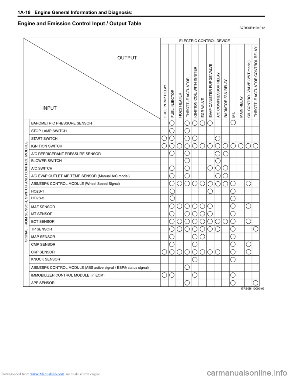
Engine and Emission Control Input / Output TableS7RS0B1101012
INPUTOUTPUT
ELECTRIC CONTROL DEVICE
BAROMETRIC PRESSURE SENSOR
STOP LAMP SWITCH
START SWITCH
IGNITION SWITCH
A/C REFRIGERANT PRESSURE SENSOR
BLOWER SWITCH
A/C SWITCH
A/C EVAP OUTLET AIR TEMP. SENSOR (Manual A/C model)
ABS/ESP
® CONTROL MODULE (Wheel Speed Signal)
HO2S-1
HO2S-2
IAT SENSOR MAF SENSOR
ECT SENSOR
TP SENSOR
MAP SENSOR
CMP SENSOR
CKP SENSOR
KNOCK SENSOR
ABS/ESP
® CONTROL MODULE (ABS active signal / ESP® status signal)
IMMOBILIZER CONTROL MODULE (in ECM)
APP SENSOR
FUEL PUMP RELAY
FUEL INJECTOR
HO2S HEATER THROTTLE ACTUATOR
THROTTLE ACTUATOR CONTROL RELAY
IGNITION COIL WITH IGNITER
EGR VALVE
EVAP CANISTER PURGE VALVEA/C COMPRESSOR RELAY RADIATOR FAN RELAY
MIL
MAIN RELAY
OIL CONTROL VALVE
(VVT model)
SIGNAL FROM SENSOR, SWITCH AND CONTROL MODULE
I7RS0B110009-03
Page 78 of 1496
Downloaded from www.Manualslib.com manuals search engine 1A-28 Engine General Information and Diagnosis:
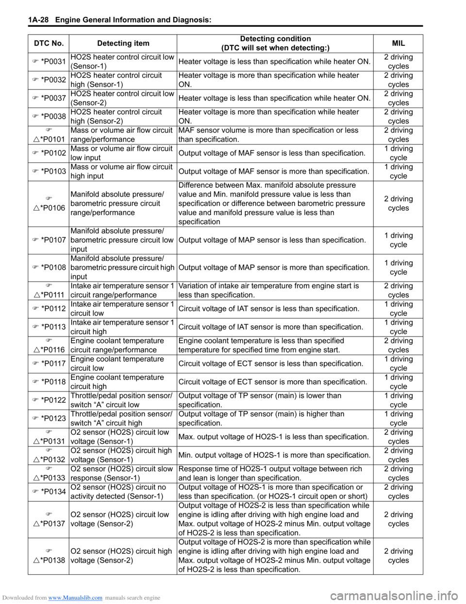
) *P0031 HO2S heater control circuit low
(Sensor-1) Heater voltage is less than specification while heater ON. 2 driving
cycles
) *P0032 HO2S heater control circuit
high (Sensor-1) Heater voltage is more than
specification while heater
ON. 2 driving
cycles
) *P0037 HO2S heater control circuit low
(Sensor-2) Heater voltage is less than specification while heater ON. 2 driving
cycles
) *P0038 HO2S heater control circuit
high (Sensor-2) Heater voltage is more than
specification while heater
ON. 2 driving
cycles
)
U *P0101 Mass or volume air flow circuit
range/performance MAF sensor volume is more
than specification or less
than specification. 2 driving
cycles
) *P0102 Mass or volume air flow circuit
low input Output voltage of MAF sensor is less than specification. 1 driving
cycle
) *P0103 Mass or volume air flow circuit
high input Output voltage of MAF sensor is more than specification. 1 driving
cycle
)
U *P0106 Manifold absolute pressure/
barometric pressure circuit
range/performance Difference between Max. manifold absolute pressure
value and Min. manifold pressure value is less than
specification or difference between barometric pressure
value and manifold pressure value is less than
specification
2 driving
cycles
) *P0107 Manifold absolute pressure/
barometric pressure circuit low
input Output voltage of MAP sensor
is less than specification.1 driving
cycle
) *P0108 Manifold absolute pressure/
barometric pressure circuit high
input Output voltage of MAP sensor is more than specification.
1 driving
cycle
)
U *P0111 Intake air temperature sensor 1
circuit range/performance Variation of intake air temperature from engine start is
less than specification. 2 driving
cycles
) *P0112 Intake air temperature sensor 1
circuit low Circuit voltage of IAT sensor is less than specification. 1 driving
cycle
) *P0113 Intake air temperature sensor 1
circuit hig
h Circuit voltage of IAT sensor
is more than specification. 1 driving
cycle
)
U *P0116 Engine coolant temperature
circuit range/performance Engine coolant temperature is less than specified
temperature for specified time from engine start. 2 driving
cycles
) *P0117 Engine coolant temperature
circuit low Circuit voltage of ECT sensor
is less than specification. 1 driving
cycle
) *P0118 Engine coolant temperature
circuit high Circuit voltage of ECT sensor
is more than specification. 1 driving
cycle
) *P0122 Throttle/pedal position sensor/
switch “A” circuit low Output voltage of TP sensor (main) is lower than
specification. 1 driving
cycle
) *P0123 Throttle/pedal position sensor/
switch “A” circuit high Output voltage of TP sensor (main) is higher than
specification. 1 driving
cycle
)
U *P0131 O2 sensor (HO2S) circuit low
voltage (Sensor-1)
Max. output voltage of HO2S-1
is less than specification.2 driving
cycles
)
U *P0132 O2 sensor (HO2S) circuit high
voltage (Sensor-1)
Min. output voltage of HO2S-1
is more than specification. 2 driving
cycles
)
U *P0133 O2 sensor (HO2S) circuit slow
response (Sensor-1) Response time of HO2S-1 output voltage between rich
and lean is longer than specification. 2 driving
cycles
) *P0134 O2 sensor (HO2S) circuit no
activity detected (Sensor-1) Output voltage of HO2S-1 is
more than specification or
less than specification. (or HO2S-1 circuit open or short) 2 driving
cycles
)
U *P0137 O2 sensor (HO2S) circuit low
voltage (Sensor-2) Output voltage of HO2S-2 is
less than specification while
engine is idling after driving with high engine load and
Max. output voltage of HO2S-2 minus Min. output voltage
of HO2S-2 is less than specification. 2 driving
cycles
)
U *P013
8 O2 sensor (HO2S) circuit high
voltage (Sensor-2) Output voltage of HO2S-2 is
more than specification while
engine is idling after driving with high engine load and
Max. output voltage of HO2S-2 minus Min. output voltage
of HO2S-2 is less than specification. 2 driving
cycles
DTC No. Detecting item
Detecting condition
(DTC will set when detecting:) MIL
Page 80 of 1496
Downloaded from www.Manualslib.com manuals search engine 1A-30 Engine General Information and Diagnosis:
)
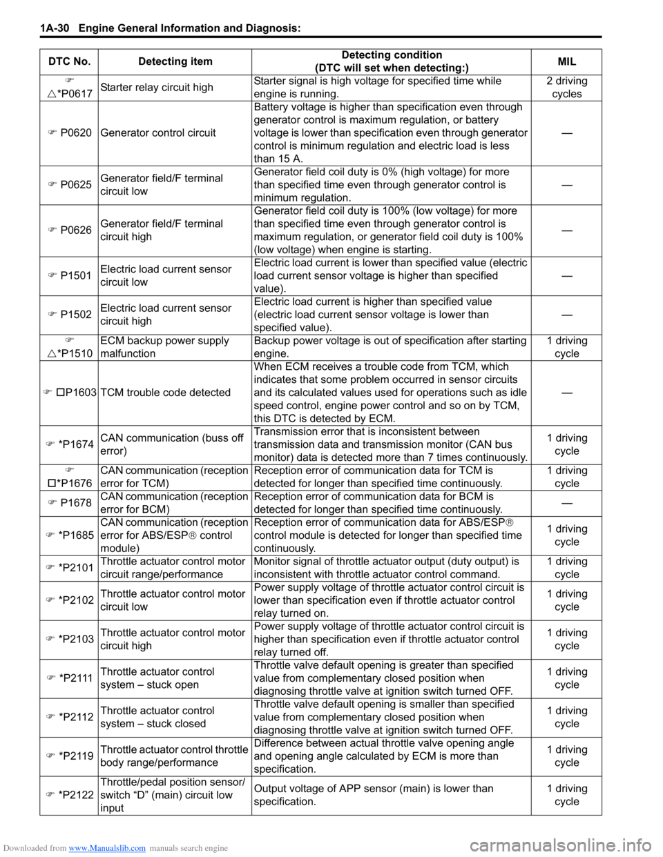
U *P0617 Starter relay circuit high Starter signal is high voltage for specified time while
engine is running. 2 driving
cycles
) P0620 Generator control circuit Battery voltage is higher than specification even through
generator control is maximum regulation, or battery
voltage is lower than specification even through generator
control is minimum regulation
and electric load is less
than 15 A. —
) P0625 Generator field/F terminal
circuit low Generator field coil duty is
0% (high voltage) for more
than specified time even through generator control is
minimum regulation. —
) P0626 Generator field/F terminal
circuit high Generator field coil duty is
100% (low voltage) for more
than specified time even through generator control is
maximum regulation, or generator field coil duty is 100%
(low voltage) when engine is starting. —
) P1501 Electric load current sensor
circuit low Electric load current is lowe
r than specified value (electric
load current sensor voltage is higher than specified
value). —
) P1502 Electric load current sensor
circuit high Electric load current is higher than specified value
(electric load current sens
or voltage is lower than
specified value). —
)
U *P1510 ECM backup power supply
malfunction Backup power voltage is out of
specification after starting
engine. 1 driving
cycle
) † P1603 TCM trouble code detected When ECM receives a trouble code from TCM, which
indicates that some problem occurred in sensor circuits
and its calculated values used for operations such as idle
speed control, engine power control and so on by TCM,
this DTC is detected by ECM. —
) *P1674 CAN communication (buss off
error) Transmission error that
is inconsistent between
transmission data and transmission monitor (CAN bus
monitor) data is detected more than 7 times continuously. 1 driving
cycle
)
† *P1676 CAN communication (reception
error for TCM) Reception error of communication data for TCM is
detected for longer than specified time continuously. 1 driving
cycle
) P1678 CAN communication (reception
error for BCM) Reception error of communication data for BCM is
detected for longer than specified time continuously.
—
) *P1685 CAN communication (reception
error for ABS/ESP
® control
module) Reception error of communication data for ABS/ESP
®
co
ntrol module is detected for longer than specified time
continuously. 1 driving
cycle
) *P2101 Throttle actuator control motor
circuit range/performance Monitor signal of throttle actuator output (duty output) is
inconsistent with throttle actuator control command. 1 driving
cycle
) *P2102 Throttle actuator control motor
circuit low Power supply voltage of throttle actuator control circuit is
lower than specification even
if throttle actuator control
relay turned on. 1 driving
cycle
) *P2103 Throttle actuator control motor
circuit high Power supply voltage of throttle actuator control circuit is
higher than specification even if throttle actuator control
relay turned off. 1 driving
cycle
) *P2111 Throttle actuator control
system – stuck open Throttle valve default opening is greater than specified
value from complementary closed position when
diagnosing throttle valve at ignition switch turned OFF. 1 driving
cycle
) *P2112 Throttle actuator control
system – stuck closed Throttle valve default opening is smaller than specified
value from complementary closed position when
diagnosing throttle valve at ignition switch turned OFF. 1 driving
cycle
) *P2119 Throttle actuator control throttle
body range/performance Difference between actual throttle valve opening angle
and opening angle calculated by ECM is more than
specification. 1 driving
cycle
) *P2122 Throttle/pedal position sensor/
switch “D” (main) circuit low
input Output voltage of APP sensor (main) is lower than
specification.
1 driving
cycle
DTC No. Detecting item
Detecting condition
(DTC will set when detecting:) MIL
Page 82 of 1496
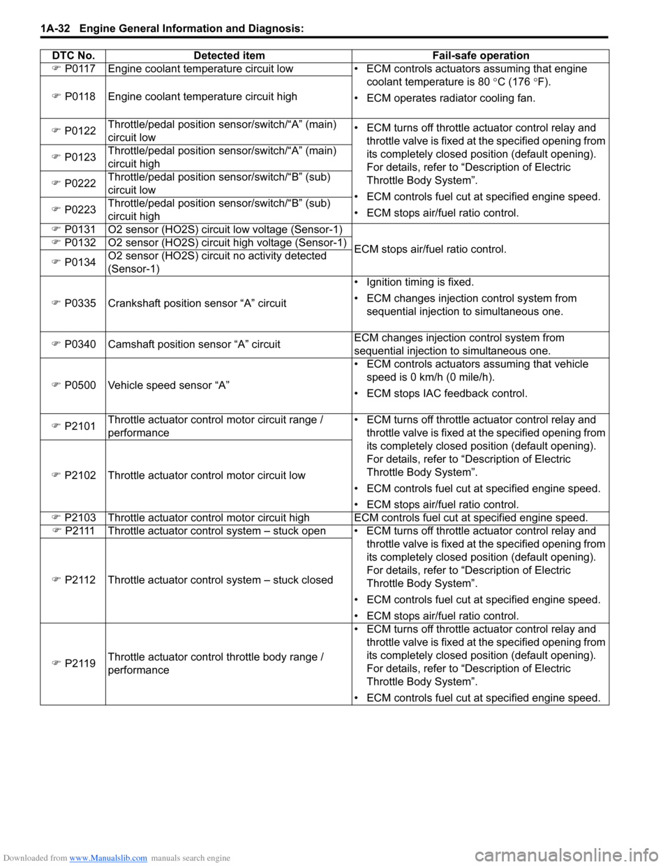
Downloaded from www.Manualslib.com manuals search engine 1A-32 Engine General Information and Diagnosis:
) P0117 Engine coolant temperature circuit low • EC M controls actuators assuming that engine
coolant temperature is 80 °C (176 °F).
• ECM operates radiator cooling fan.
)
P0118 Engine coolant temperature circuit high
) P0122 Throttle/pedal position sensor/switch/“A” (main)
circuit low • ECM turns off throttle actuator control relay and
throttle valve is fixed at the specified opening from
its completely closed position (default opening).
For details, refer to “Description of Electric
Throttle Body System”.
• ECM controls fuel cut at specified engine speed.
• ECM stops air/fuel ratio control.
)
P0123 Throttle/pedal position sensor/switch/“A” (main)
circuit high
) P0222 Throttle/pedal position sensor/switch/“B” (sub)
circuit low
) P0223 Throttle/pedal position sensor/switch/“B” (sub)
circuit high
) P0131 O2 sensor (HO2S) circuit low voltage (Sensor-1)
ECM stops air/fuel ratio control.
)
P0132 O2 sensor (HO2S) circuit high voltage (Sensor-1)
) P0134 O2 sensor (HO2S) circuit no activity detected
(Sensor-1)
) P0335 Crankshaft position sensor “A” circuit • Ignition timing is fixed.
• ECM changes injection control system from
sequential injection to simultaneous one.
) P0340 Camshaft position sensor “A” circuit ECM changes injection
control system from
sequential injection to simultaneous one.
) P0500 Vehicle speed sensor “A” • ECM controls actuators assuming that vehicle
speed is 0 km/h (0 mile/h).
• ECM stops IAC feedback control.
) P2101 Throttle actuator control motor circuit range /
performance • ECM turns off throttle actuator control relay and
throttle valve is fixed at the specified opening from
its completely closed position (default opening).
For details, refer to “Description of Electric
Throttle Body System”.
• ECM controls fuel cut at specified engine speed.
• ECM stops air/fuel ratio control.
)
P2102 Throttle actuator control motor circuit low
) P2103 Throttle actuator control motor circuit high ECM controls fuel cut at specified engine speed.
) P2111 Throttle actuator control system – stuck open • EC M turns off throttle actuator control relay and
throttle valve is fixed at the specified opening from
its completely closed position (default opening).
For details, refer to “Description of Electric
Throttle Body System”.
• ECM controls fuel cut at specified engine speed.
• ECM stops air/fuel ratio control.
)
P2112 Throttle actuator control system – stuck closed
) P2119 Throttle actuator control throttle body range /
performance • ECM turns off throttle actuator control relay and
throttle valve is fixed at the specified opening from
its completely closed position (default opening).
For details, refer to “Description of Electric
Throttle Body System”.
• ECM controls fuel cut at specified engine speed.
DTC No.
Detected item Fail-safe operation