Psi SUZUKI SWIFT 2006 2.G Service Owner's Manual
[x] Cancel search | Manufacturer: SUZUKI, Model Year: 2006, Model line: SWIFT, Model: SUZUKI SWIFT 2006 2.GPages: 1496, PDF Size: 34.44 MB
Page 744 of 1496
Downloaded from www.Manualslib.com manuals search engine 5A-100 Automatic Transmission/Transaxle:
Operation Check
Shift solenoid valve-A (No.1) and -B (No.2)
CAUTION!
• Do not insert air gun against strainer installed on inlet of solenoid valve too
deeply, when blowing air into solenoid
valve. If not, the strainer will be damaged.
• Be very careful as dust etc. does not enter when solenoid valves are inspected.
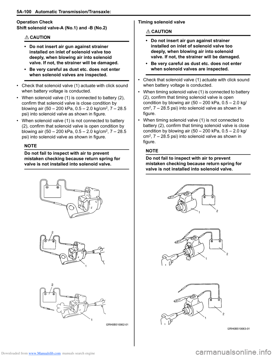
• Check that solenoid valve (1) actuate with click sound when battery voltage is conducted.
• When solenoid valve (1) is connected to battery (2), confirm that solenoid valve is close condition by
blowing air (50 – 200 kPa, 0.5 – 2.0 kg/cm
2, 7 – 28.5
psi) into solenoid valve as shown in figure.
• When solenoid valve (1) is not connected to battery (2), confirm that solenoid valve is open condition by
blowing air (50 – 200 kPa, 0.5 – 2.0 kg/cm
2, 7 – 28.5
psi) into solenoid valve as shown in figure.
NOTE
Do not fail to inspect with air to prevent
mistaken checking because return spring for
valve is not installe d into solenoid valve.
Timing solenoid valve
CAUTION!
• Do not insert air gun against strainer
installed on inlet of solenoid valve too
deeply, when blowing air into solenoid
valve. If not, the strainer will be damaged.
• Be very careful as dust etc. does not enter when solenoid valves are inspected.
• Check that solenoid valve (1) actuate with click sound
when battery voltage is conducted.
• When timing solenoid valve (1 ) is connected to battery
(2), confirm that timing solenoid valve is open
condition by blowing air (50 – 200 kPa, 0.5 – 2.0 kg/
cm
2, 7 – 28.5 psi) into solenoid valve as shown in
figure.
• When timing solenoid valve (1) is not connected to battery (2), confirm that timi ng solenoid valve is close
condition by blowing air (50 – 200 kPa, 0.5 – 2.0 kg/
cm
2, 7 – 28.5 psi) into solenoid valve as shown in
figure.
NOTE
Do not fail to inspect with air to prevent
mistaken checking because return spring for
valve is not installed into solenoid valve.
I2RH0B510062-01I2RH0B510063-01
Page 756 of 1496
Downloaded from www.Manualslib.com manuals search engine 5A-112 Automatic Transmission/Transaxle:
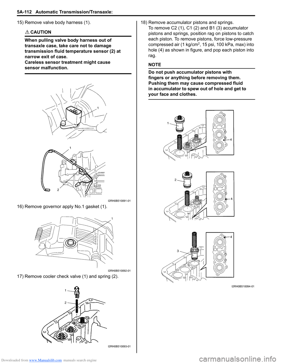
15) Remove valve body harness (1).
CAUTION!
When pulling valve body harness out of
transaxle case, take care not to damage
transmission fluid temperature sensor (2) at
narrow exit of case.
Careless sensor treatment might cause
sensor malfunction.
16) Remove governor apply No.1 gasket (1).
17) Remove cooler check valve (1) and spring (2).18) Remove accumulator pistons and springs.
To remove C2 (1), C1 (2) and B1 (3) accumulator
pistons and springs, position rag on pistons to catch
each piston. To remove pistons, force low-pressure
compressed air (1 kg/cm
2, 15 psi, 100 kPa, max) into
hole (4) as shown in figure, and pop each piston into
rag.
NOTE
Do not push accumulator pistons with
fingers or anything before removing them.
Pushing them may cause compressed fluid
in accumulator to spew out of hole and get to
your face and clothes.
I2RH0B510091-01
I2RH0B510092-01
I2RH0B510093-01
I2RH0B510094-01
Page 762 of 1496
Downloaded from www.Manualslib.com manuals search engine 5A-118 Automatic Transmission/Transaxle:
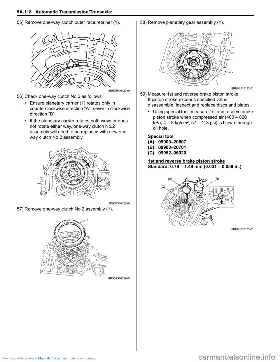
55) Remove one-way clutch outer race retainer (1).
56) Check one-way clutch No.2 as follows.• Ensure planetary carrier (1) rotates only in counterclockwise direction “A”, never in clockwise
direction “B”.
• If the planetary carrier rotates both ways or does not rotate either way, one-way clutch No.2
assembly will need to be replaced with new one-
way clutch No.2 assembly.
57) Remove one-way clutch No.2 assembly (1). 58) Remove planetary gear assembly (1).
59) Measure 1st and reverse brake piston stroke.
If piston stroke exce eds specified value,
disassemble, inspect and replace discs and plates.
• Using special tool, measure 1st and reserve brake piston stroke when compressed air (400 – 800
kPa, 4 – 8 kg/cm
2, 57 – 113 psi) is blown through
oil hole.
Special tool
(A): 09900–20607
(B): 09900–20701
(C): 09952–06020
1st and reverse brake piston stroke
Standard: 0.79 – 1.49 mm (0.031 – 0.059 in.)
I2RH0B510129-01
I2RH0B510130-01
1
I4RS0A510039-01
I2RH0B510132-01
I2RH0B510133-01
Page 768 of 1496
Downloaded from www.Manualslib.com manuals search engine 5A-124 Automatic Transmission/Transaxle:
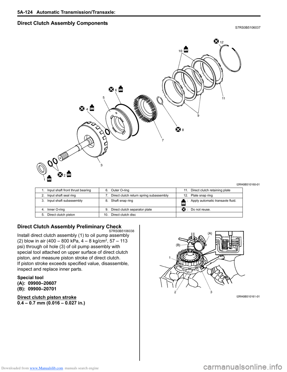
Direct Clutch Assembly ComponentsS7RS0B5106037
Direct Clutch Assembly Preliminary CheckS7RS0B5106038
Install direct clutch assembly (1) to oil pump assembly
(2) blow in air (400 – 800 kPa, 4 – 8 kg/cm2, 57 – 113
psi) through oil hole (3) of oil pump assembly with
special tool attached on uppe r surface of direct clutch
piston, and measure piston stroke of direct clutch.
If piston stroke exceeds sp ecified value, disassemble,
inspect and replace inner parts.
Special tool
(A): 09900–20607
(B): 09900–20701
Direct clutch piston stroke
0.4 – 0.7 mm (0.016 – 0.027 in.)
I2RH0B510160-01
1. Input shaft front thrust bearing 6. Outer O-ring 11. Direct clutch retaining plate
2. Input shaft seal ring 7. Direct clutch return spring subassembly 12. Plate snap ring
3. Input shaft subassembly 8. Shaft snap ring : Apply automatic transaxle fluid.
4. Inner O-ring 9. Direct clutch separator plate : Do not reuse.
5. Direct clutch piston 10. Direct clutch disc
I2RH0B510161-01
Page 769 of 1496
Downloaded from www.Manualslib.com manuals search engine Automatic Transmission/Transaxle: 5A-125
Direct Clutch Assembly Disassembly and
Reassembly
S7RS0B5106039
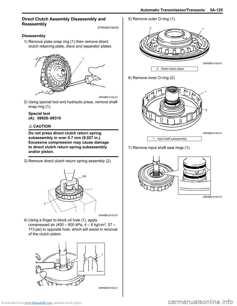
Disassembly1) Remove plate snap ring (1) then remove direct clutch retaining plate, discs and separator plates.
2) Using special tool and hydraulic press, remove shaft snap ring (1).
Special tool
(A): 09926–98310
CAUTION!
Do not press direct clutch return spring
subassembly in over 0.7 mm (0.027 in.).
Excessive compression may cause damage
to direct clutch return spring subassembly
and/or piston.
3) Remove direct clutch re turn spring assembly (2).
4) Using a finger to block oil hole (1), apply compressed air (400 – 800 kPa, 4 – 8 kg/cm
2, 57 –
113 psi) to opposite hole, which will assist in removal
of the clutch piston. 5) Remove outer O-ring (1).
6) Remove inner O-ring (2).
7) Remove input shaft seal rings (1).
I2RH0B510162-01
I2RH0B510163-01
I2RH0B510164-01
2. Direct clutch piston
1. Input shaft subassembly
I2RH0B510165-01
I2RH0B510166-01
I2RH0B510167-01
Page 771 of 1496
Downloaded from www.Manualslib.com manuals search engine Automatic Transmission/Transaxle: 5A-127
Direct Clutch Assembly InspectionS7RS0B5106040
Clutch Discs, Plates and Retaining Plate
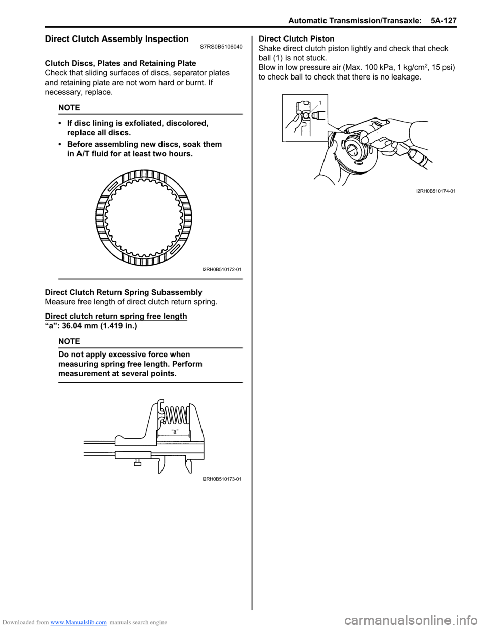
Check that sliding surfaces of discs, separator plates
and retaining plate are not worn hard or burnt. If
necessary, replace.
NOTE
• If disc lining is exfoliated, discolored, replace all discs.
• Before assembling new discs, soak them in A/T fluid for at least two hours.
Direct Clutch Return Spring Subassembly
Measure free length of direct clutch return spring.
Direct clutch return spring free length
“a”: 36.04 mm (1.419 in.)
NOTE
Do not apply excessive force when
measuring spring free length. Perform
measurement at several points.
Direct Clutch Piston
Shake direct clutch piston lightly and check that check
ball (1) is not stuck.
Blow in low pressure air (Max. 100 kPa, 1 kg/cm
2, 15 psi)
to check ball to check that there is no leakage.
I2RH0B510172-01
I2RH0B510173-01
I2RH0B510174-01
Page 773 of 1496
Downloaded from www.Manualslib.com manuals search engine Automatic Transmission/Transaxle: 5A-129
Forward and Reverse Clutch Assembly
Preliminary Check
S7RS0B5106042
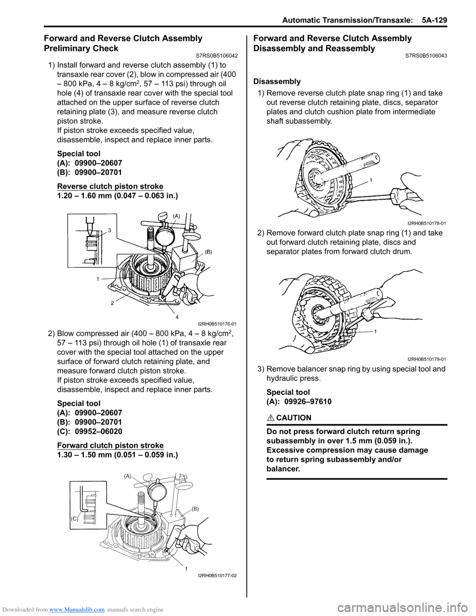
1) Install forward and reverse clutch assembly (1) to
transaxle rear cover (2), blow in compressed air (400
– 800 kPa, 4 – 8 kg/cm
2, 57 – 113 psi) through oil
hole (4) of transaxle rear cover with the special tool
attached on the upper surf ace of reverse clutch
retaining plate (3), and measure reverse clutch
piston stroke.
If piston stroke exce eds specified value,
disassemble, inspect and replace inner parts.
Special tool
(A): 09900–20607
(B): 09900–20701
Reverse clutch piston stroke
1.20 – 1.60 mm (0.047 – 0.063 in.)
2) Blow compressed air (400 – 800 kPa, 4 – 8 kg/cm
2,
57 – 113 psi) through oil hole (1) of transaxle rear
cover with the special tool attached on the upper
surface of forward clutch retaining plate, and
measure forward clutch piston stroke.
If piston stroke exce eds specified value,
disassemble, inspect and replace inner parts.
Special tool
(A): 09900–20607
(B): 09900–20701
(C): 09952–06020
Forward clutch piston stroke
1.30 – 1.50 mm (0.051 – 0.059 in.)
Forward and Reverse Clutch Assembly
Disassembly and Reassembly
S7RS0B5106043
Disassembly
1) Remove reverse clutch plate snap ring (1) and take out reverse clutch retaini ng plate, discs, separator
plates and clutch cushion plate from intermediate
shaft subassembly.
2) Remove forward clutch plate snap ring (1) and take out forward clutch retaining plate, discs and
separator plates from forward clutch drum.
3) Remove balancer snap ring by using special tool and hydraulic press.
Special tool
(A): 09926–97610
CAUTION!
Do not press forward clutch return spring
subassembly in over 1.5 mm (0.059 in.).
Excessive compression may cause damage
to return spring subassembly and/or
balancer.
I2RH0B510176-01
I2RH0B510177-02
I2RH0B510178-01
I2RH0B510179-01
Page 774 of 1496
Downloaded from www.Manualslib.com manuals search engine 5A-130 Automatic Transmission/Transaxle:
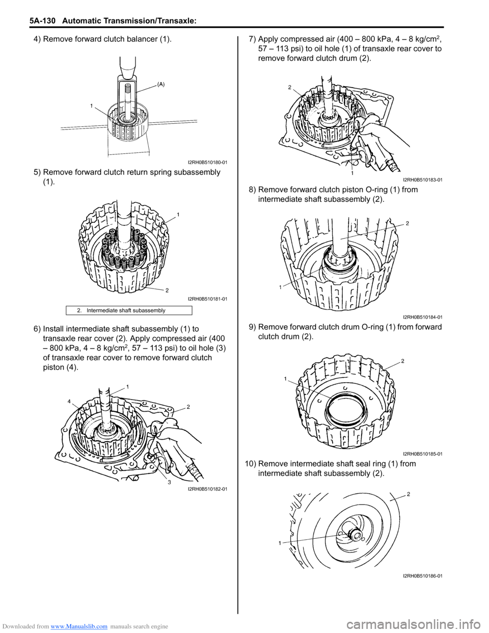
4) Remove forward clutch balancer (1).
5) Remove forward clutch return spring subassembly
(1).
6) Install intermed iate shaft subassembly (1) to
transaxle rear cover (2). Apply compressed air (400
– 800 kPa, 4 – 8 kg/cm
2, 57 – 113 psi) to oil hole (3)
of transaxle rear cover to remove forward clutch
piston (4). 7) Apply compressed air (400 – 800 kPa, 4 – 8 kg/cm
2,
57 – 113 psi) to oil hole (1) of transaxle rear cover to
remove forward clutch drum (2).
8) Remove forward clutch piston O-ring (1) from intermediate shaft subassembly (2).
9) Remove forward clutch drum O-ring (1) from forward clutch drum (2).
10) Remove intermediate shaft seal ring (1) from intermediate shaft subassembly (2).
2. Intermediate shaft subassembly
I2RH0B510180-01
I2RH0B510181-01
I2RH0B510182-01
I2RH0B510183-01
I2RH0B510184-01
I2RH0B510185-01
I2RH0B510186-01
Page 778 of 1496
Downloaded from www.Manualslib.com manuals search engine 5A-134 Automatic Transmission/Transaxle:
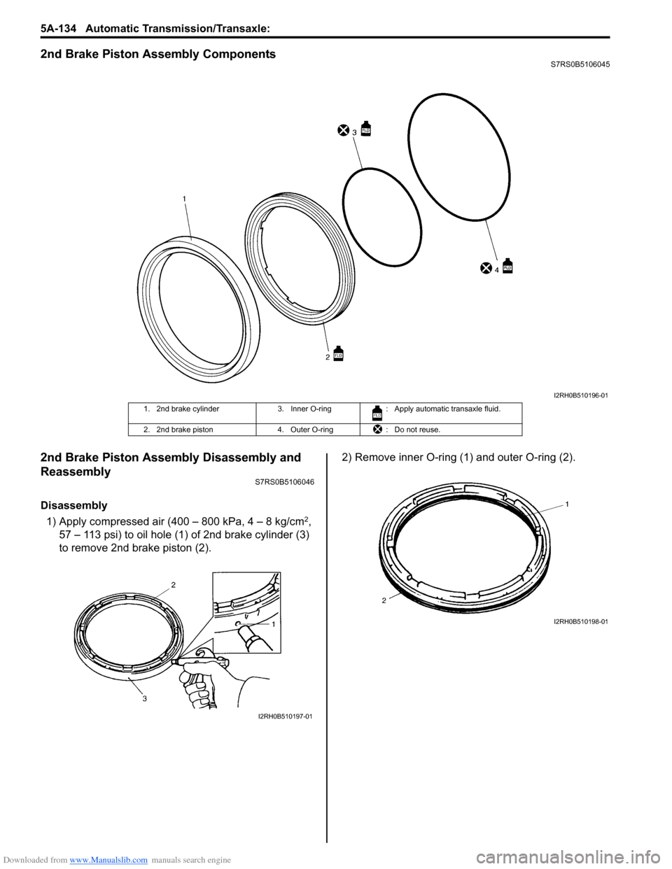
2nd Brake Piston Assembly ComponentsS7RS0B5106045
2nd Brake Piston Assembly Disassembly and
Reassembly
S7RS0B5106046
Disassembly1) Apply compressed air (400 – 800 kPa, 4 – 8 kg/cm
2,
57 – 113 psi) to oil hole (1) of 2nd brake cylinder (3)
to remove 2nd brake piston (2). 2) Remove inner O-ring (1) and outer O-ring (2).
I2RH0B510196-01
1. 2nd brake cylinder
3. Inner O-ring: Apply automatic transaxle fluid.
2. 2nd brake piston 4. Outer O-ring: Do not reuse.
I2RH0B510197-01
I2RH0B510198-01
Page 780 of 1496
Downloaded from www.Manualslib.com manuals search engine 5A-136 Automatic Transmission/Transaxle:
Transaxle Rear Cover (O/D and 2nd Coast Brake
Piston) Assembly Disassembly and
Reassembly
S7RS0B5106048
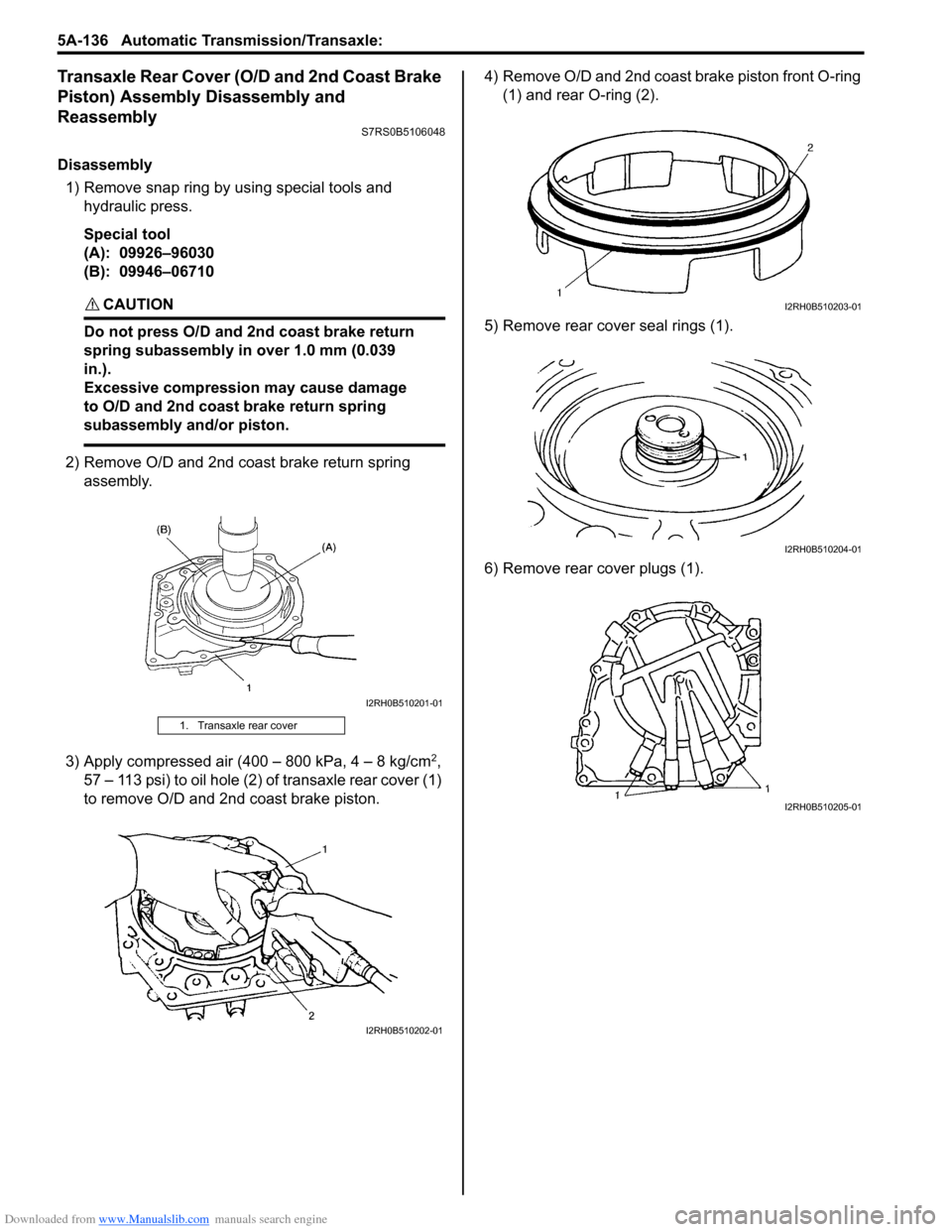
Disassembly1) Remove snap ring by using special tools and hydraulic press.
Special tool
(A): 09926–96030
(B): 09946–06710
CAUTION!
Do not press O/D and 2nd coast brake return
spring subassembly in over 1.0 mm (0.039
in.).
Excessive compression may cause damage
to O/D and 2nd coast brake return spring
subassembly and/or piston.
2) Remove O/D and 2nd coast brake return spring assembly.
3) Apply compressed air (400 – 800 kPa, 4 – 8 kg/cm
2,
57 – 113 psi) to oil hole (2) of transaxle rear cover (1)
to remove O/D and 2nd coast brake piston. 4) Remove O/D and 2nd coast brake piston front O-ring
(1) and rear O-ring (2).
5) Remove rear cove r seal rings (1).
6) Remove rear cover plugs (1).
1. Transaxle rear cover
I2RH0B510201-01
I2RH0B510202-01
I2RH0B510203-01
I2RH0B510204-01
I2RH0B510205-01