Rear door SUZUKI SWIFT 2006 2.G Service Owner's Manual
[x] Cancel search | Manufacturer: SUZUKI, Model Year: 2006, Model line: SWIFT, Model: SUZUKI SWIFT 2006 2.GPages: 1496, PDF Size: 34.44 MB
Page 1243 of 1496
Downloaded from www.Manualslib.com manuals search engine Wiring Systems: 9A-72
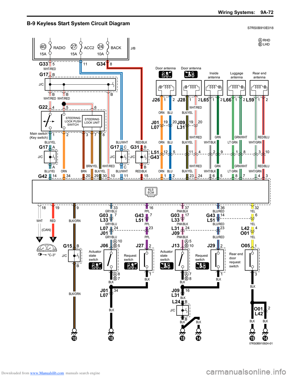
B-9 Keyless Start System Circuit DiagramS7RS0B910E018
BLKBLK
BLK
BLKBLK
YELBLU/REDPNK/BLKPPLGRY/BLU
YELBLU/REDPNK/BLKPPLGRY/BLU
YELBLU/REDPNK/BLKPPLGRY/BLU
G33
KLS
ECM
WHT/RED
WHT/REDWHT/RED
BLU/YEL
WHTRED
ORN
BLU/YEL
"C-3"
WR
G42143420
1819
BLK/ORN
BLK/ORN
9
5
J/B
15A RADIO
40
G348
10A
BACK
24
11
15A
ACC2
27
B
B
B
J/C
G17
B
A
A
J/C
BLU/WHT
BLU/WHT
C
C
J/C
G17
Main switch
(Key switch)
STEERING
LOCK PUSH SWITCH
G22456
1
O051
3
2
BRN29
BRN/YEL
301011RED/BLK
RED/BLK
B
B
J/C
Rear end
door
request
switch
G31
15ORN
ORN
ORN
1BLK/YEL
WHT/RED
378
STEERING
LOCK UNIT
Door antenna
L51
G4312
J01
L07 J261912
BLU
BLU
BLU
2
5
20
WHT/BLK
WHT/BLK6
Inside
antenna
2
12
GRN
GRN
5
9
LT GRN
LT GRN8
Luggage antenna
1
12
GRN/WHT
GRN/WHT
7
8
BLK/YEL
BLK/YEL
BLK/YEL
23
Door antenna
11
J09
L31 J28 L65 L66
WHT/GRN
WHT/GRN4
Rear end
antenna
3
12
RED/BLU
RED/BLU
3
10
L59
1912
WHT/RED
WHT/RED
WHT/RED
24
4
20
G17
B
B
J/C
G15
10
BLK
BLKBLK
32
J292
1
Request
switch
36
1914
J13
Actuator
state
switch
O01 L422
16
BLK
37
1814
J09
L31
J272
1
Request
switch
16
J06
Actuator
state
switch
34
BLK
BLK
33
18
J01
L07
(CAN) RHD
A
LHD
B
AB10
5AB5
10
AB8
7AB7
8
614G43
L5117G03 L337G43 L517G03 L33
423242324L42
O01
L31
J09
L07
J01
B
J/C
B
L24
I7RS0B910924-01
Page 1253 of 1496
Downloaded from www.Manualslib.com manuals search engine Wiring Systems: 9A-82
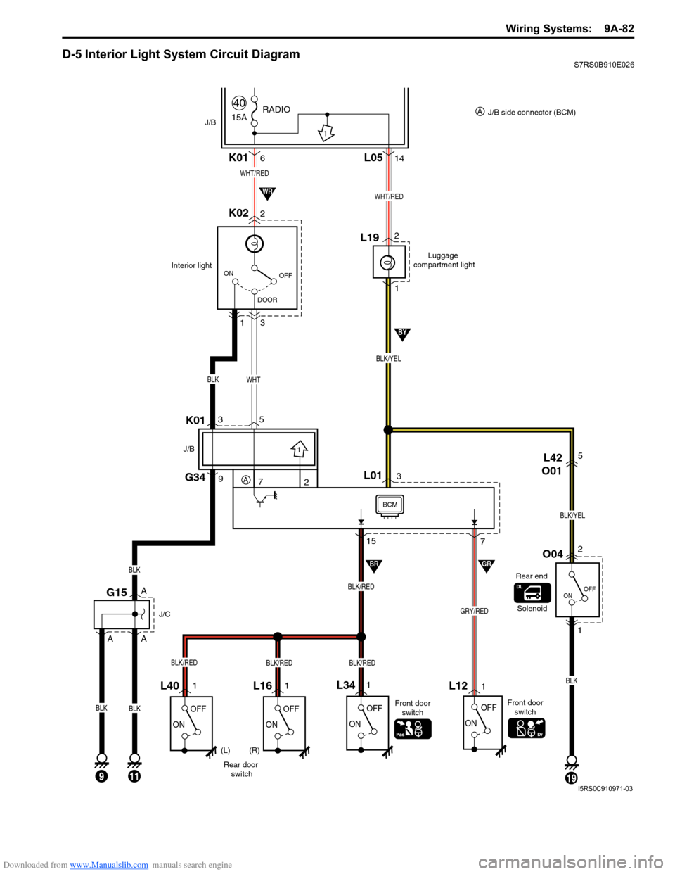
D-5 Interior Light System Circuit DiagramS7RS0B910E026
15A
40RADIO
J/B
OFF
DOOR
ON
K02 K012 6
3
1
Interior light
15
7
OFF
ON
OFF
ON
L121
1
GRY/RED
BLK
OFF
ONOFF
ON
L16 L341L401
Rear door
switch Front door
switch
BLK/RED
BLK
BLK
BLK
L0514
WHT/RED
G15
J/C
A
A
5
7G34
K01
J/B
L01
Luggage
compartment light
2
1
3L19
WHT/RED
BLK/YEL
WHT
1119
OFF
ON
O042
L42
O015
1
BLK/YEL
3
Solenoid
2
1
1
J/B side connector (BCM)
A
(L) (R) Front door
switch
A
BLK/REDBLK/REDBLK/RED
Rear end
9
BRGR
9
BLK
A
BY
WR
BCM
I5RS0C910971-03
Page 1284 of 1496
Downloaded from www.Manualslib.com manuals search engine 9B-2 Lighting Systems:
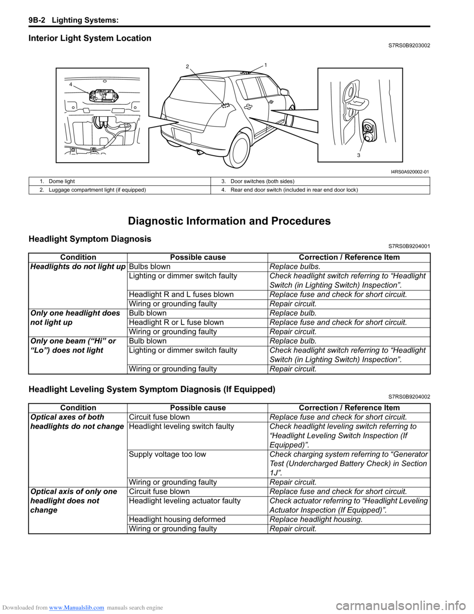
Interior Light System LocationS7RS0B9203002
Diagnostic Information and Procedures
Headlight Symptom DiagnosisS7RS0B9204001
Headlight Leveling System Symptom Diagnosis (If Equipped)S7RS0B9204002
13
2
4
I4RS0A920002-01
1. Dome light 3. Door switches (both sides)
2. Luggage compartment light (if equipped) 4. Rear end door switch (included in rear end door lock)
ConditionPossible cause Correction / Reference Item
Headlights do not light up Bulbs blown Replace bulbs.
Lighting or dimmer switch faulty Check headlight switch referring to “Headlight
Switch (in Lighting Switch) Inspection”.
Headlight R and L fuses blown Replace fuse and check for short circuit.
Wiring or grounding faulty Repair circuit.
Only one headlight does
not light up Bulb blown
Replace bulb.
Headlight R or L fuse blown Replace fuse and check for short circuit.
Wiring or grounding faulty Repair circuit.
Only one beam (“Hi” or
“Lo”) does not light Bulb blown
Replace bulb.
Lighting or dimmer switch faulty Check headlight switch referring to “Headlight
Switch (in Lighting Switch) Inspection”.
Wiring or grounding faulty Repair circuit.
ConditionPossible cause Correction / Reference Item
Optical axes of both
headlights do not change Circuit fuse blown
Replace fuse and check for short circuit.
Headlight leveling switch faulty Check headlight leveling switch referring to
“Headlight Leveling Switch Inspection (If
Equipped)”.
Supply voltage too low Check charging system referring to “Generator
Test (Undercharged Battery Check) in Section
1J”.
Wiring or grounding faulty Repair circuit.
Optical axis of only one
headlight does not
change Circuit fuse blown
Replace fuse and check for short circuit.
Headlight leveling actuator faulty Check actuator referring to “Headlight Leveling
Actuator Inspection (If Equipped)”.
Headlight housing deformed Replace headlight housing.
Wiring or grounding faulty Repair circuit.
Page 1287 of 1496
Downloaded from www.Manualslib.com manuals search engine Lighting Systems: 9B-5
Interior Light Symptom DiagnosisS7RS0B9204008
NOTE
• Use of SUZUKI scan tool makes it easy to check whether a faulty condition is on the input side or
output side of BCM. For checking procedure, re fer to “Diagnosis Using Output Test Function of
SUZUKI Scan Tool” under “Scan Tool Data in Section 10B”.
• Check each part in the order from the top of the following list.
Repair Instructions
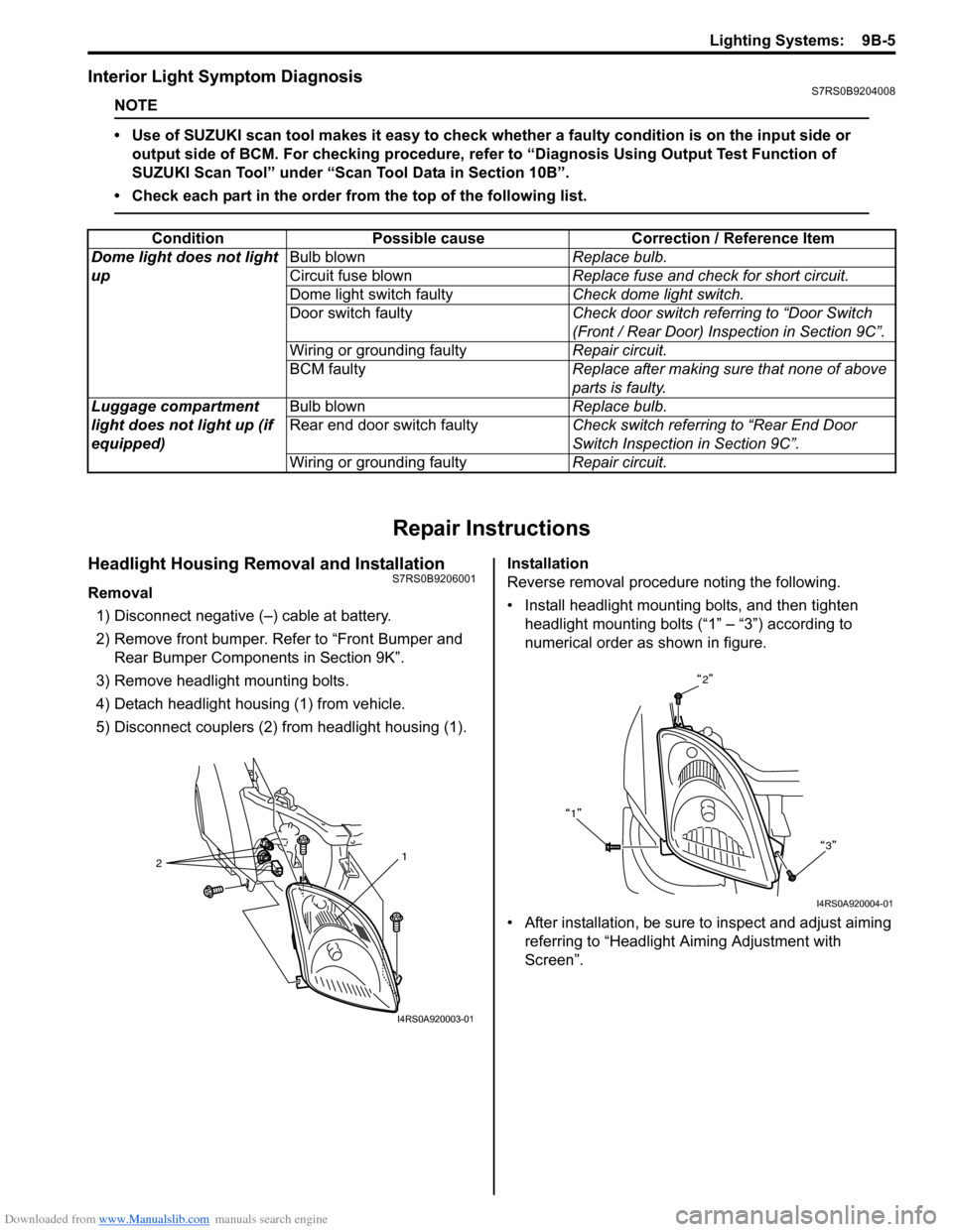
Headlight Housing Removal and InstallationS7RS0B9206001
Removal 1) Disconnect negative (–) cable at battery.
2) Remove front bumper. Refer to “Front Bumper and Rear Bumper Componen ts in Section 9K”.
3) Remove headlight mounting bolts.
4) Detach headlight housing (1) from vehicle.
5) Disconnect couplers (2) from headlight housing (1). Installation
Reverse removal procedure noting the following.
• Install headlight mounting bolts, and then tighten
headlight mounting bolts (“1” – “3”) according to
numerical order as shown in figure.
• After installation, be sure to inspect and adjust aiming referring to “Headlight Aiming Adjustment with
Screen”.
Condition Possible cause Correction / Reference Item
Dome light does not light
up Bulb blown
Replace bulb.
Circuit fuse blown Replace fuse and check for short circuit.
Dome light switch faulty Check dome light switch.
Door switch faulty Check door switch referring to “Door Switch
(Front / Rear Door) Inspection in Section 9C”.
Wiring or grounding faulty Repair circuit.
BCM faulty Replace after making sure that none of above
parts is faulty.
Luggage compartment
light does not light up (if
equipped) Bulb blown
Replace bulb.
Rear end door switch faulty Check switch referring to “Rear End Door
Switch Inspection in Section 9C”.
Wiring or grounding faulty Repair circuit.
2 1
I4RS0A920003-01
2
1 3
I4RS0A920004-01
Page 1305 of 1496
Downloaded from www.Manualslib.com manuals search engine Instrumentation / Driver Info. / Horn: 9C-10
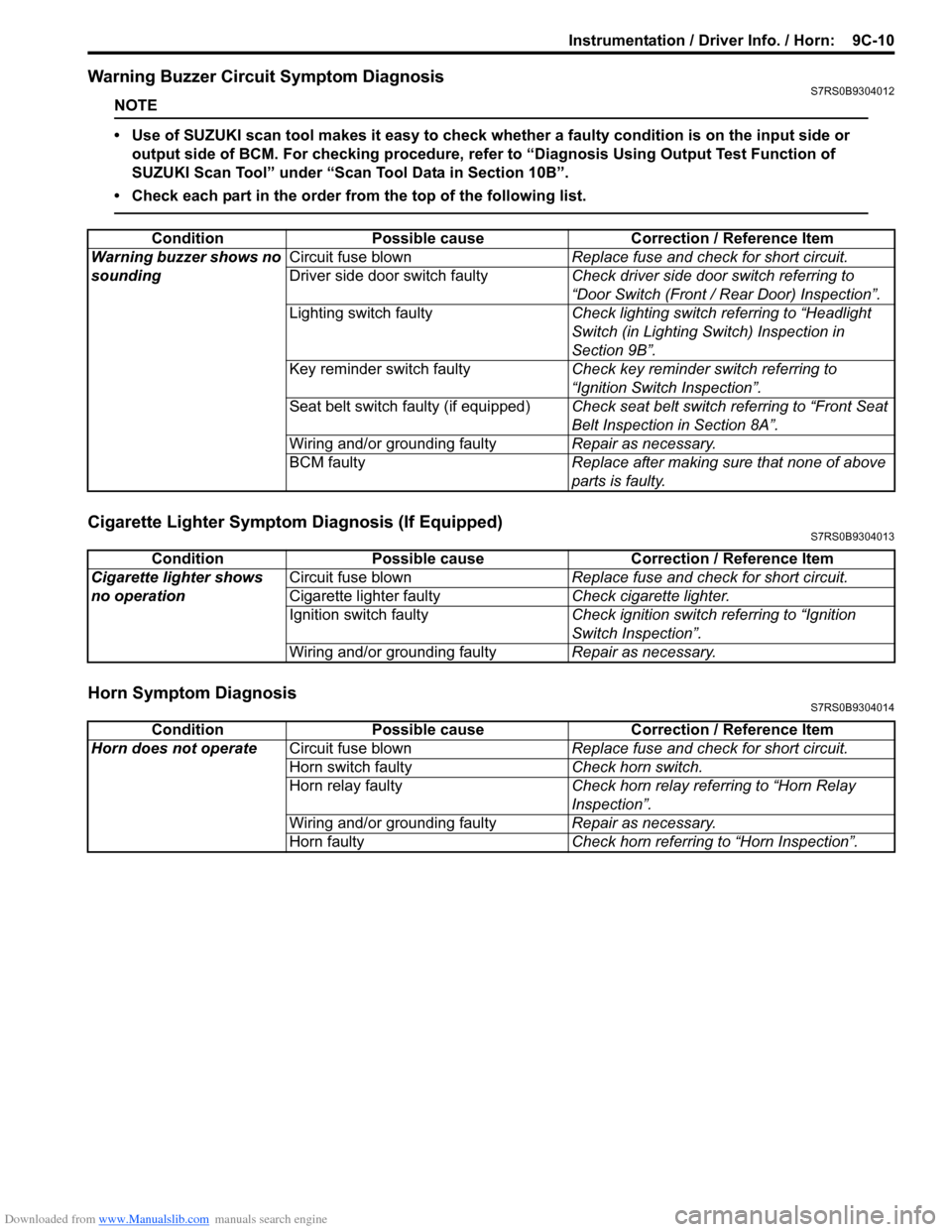
Warning Buzzer Circuit Symptom DiagnosisS7RS0B9304012
NOTE
• Use of SUZUKI scan tool makes it easy to check wh ether a faulty condition is on the input side or
output side of BCM. For checking procedure, re fer to “Diagnosis Using Output Test Function of
SUZUKI Scan Tool” under “Scan Tool Data in Section 10B”.
• Check each part in the order from the top of the following list.
Cigarette Lighter Symptom Diagnosis (If Equipped)S7RS0B9304013
Horn Symptom DiagnosisS7RS0B9304014
Condition Possible cause Correction / Reference Item
Warning buzzer shows no
sounding Circuit fuse blown
Replace fuse and check for short circuit.
Driver side door switch faulty Check driver side door switch referring to
“Door Switch (Front / Rear Door) Inspection”.
Lighting switch faulty Check lighting switch referring to “Headlight
Switch (in Lighting Switch) Inspection in
Section 9B”.
Key reminder switch faulty Check key reminder switch referring to
“Ignition Switch Inspection”.
Seat belt switch faulty (if equipped) Check seat belt switch referring to “Front Seat
Belt Inspection in Section 8A”.
Wiring and/or grounding faulty Repair as necessary.
BCM faulty Replace after making sure that none of above
parts is faulty.
ConditionPossible cause Correction / Reference Item
Cigarette lighter shows
no operation Circuit fuse blown
Replace fuse and check for short circuit.
Cigarette lighter faulty Check cigarette lighter.
Ignition switch faulty Check ignition switch referring to “Ignition
Switch Inspection”.
Wiring and/or grounding faulty Repair as necessary.
ConditionPossible cause Correction / Reference Item
Horn does not operate Circuit fuse blown Replace fuse and check for short circuit.
Horn switch faulty Check horn switch.
Horn relay faulty Check horn relay referring to “Horn Relay
Inspection”.
Wiring and/or grounding faulty Repair as necessary.
Horn faulty Check horn referring to “Horn Inspection”.
Page 1312 of 1496
Downloaded from www.Manualslib.com manuals search engine 9C-17 Instrumentation / Driver Info. / Horn:
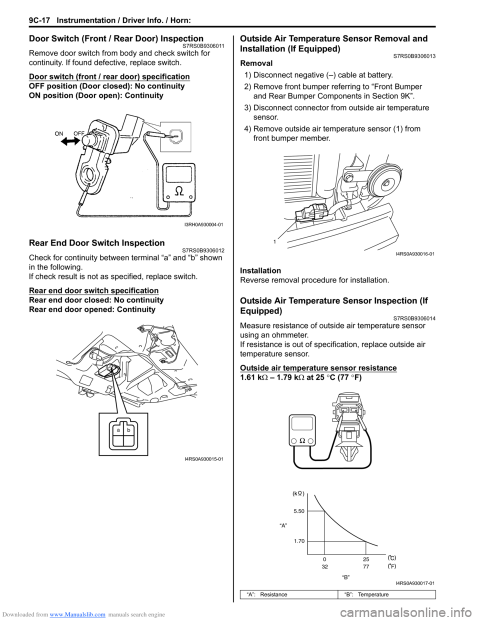
Door Switch (Front / Rear Door) InspectionS7RS0B9306011
Remove door switch from body and check switch for
continuity. If found defective, replace switch.
Door switch (front / rear door) specification
OFF position (Door closed): No continuity
ON position (Door open): Continuity
Rear End Door Switch InspectionS7RS0B9306012
Check for continuity between terminal “a” and “b” shown
in the following.
If check result is not as specified, replace switch.
Rear end door switch specification
Rear end door closed: No continuity
Rear end door opened: Continuity
Outside Air Temperature Sensor Removal and
Installation (If Equipped)
S7RS0B9306013
Removal
1) Disconnect negative (–) cable at battery.
2) Remove front bumper referring to “Front Bumper and Rear Bumper Components in Section 9K”.
3) Disconnect connector from outside air temperature sensor.
4) Remove outside air temperature sensor (1) from front bumper member.
Installation
Reverse removal procedure for installation.
Outside Air Temperature Sensor Inspection (If
Equipped)
S7RS0B9306014
Measure resistance of outside air temperature sensor
using an ohmmeter.
If resistance is out of specif ication, replace outside air
temperature sensor.
Outside air temperature sensor resistance
1.61 kΩ – 1.79 k Ω at 25 °C (77 °F)
I3RH0A930004-01
a
b
I4RS0A930015-01
“A”: Resistance “B”: Temperature
1
I4RS0A930016-01
“B”
“A”
5.50
1.70 0
32 25
77
F
I4RS0A930017-01
Page 1315 of 1496
Downloaded from www.Manualslib.com manuals search engine Instrumentation / Driver Info. / Horn: 9C-20
Rear Speaker Removal and InstallationS7RS0B9306019
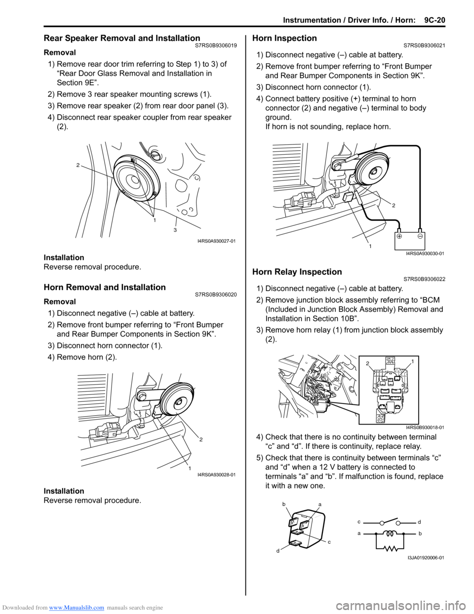
Removal
1) Remove rear door trim referring to Step 1) to 3) of “Rear Door Glass Removal and Installation in
Section 9E”.
2) Remove 3 rear speaker mounting screws (1).
3) Remove rear speaker (2) from rear door panel (3).
4) Disconnect rear speaker coupler from rear speaker (2).
Installation
Reverse removal procedure.
Horn Removal and InstallationS7RS0B9306020
Removal 1) Disconnect negative (–) cable at battery.
2) Remove front bumper referring to “Front Bumper and Rear Bumper Components in Section 9K”.
3) Disconnect horn connector (1).
4) Remove horn (2).
Installation
Reverse removal procedure.
Horn InspectionS7RS0B9306021
1) Disconnect negative (–) cable at battery.
2) Remove front bumper referring to “Front Bumper and Rear Bumper Components in Section 9K”.
3) Disconnect horn connector (1).
4) Connect battery positive (+) terminal to horn
connector (2) and negative (–) terminal to body
ground.
If horn is not sounding, replace horn.
Horn Relay InspectionS7RS0B9306022
1) Disconnect negative (–) cable at battery.
2) Remove junction block assembly referring to “BCM (Included in Junction Bl ock Assembly) Removal and
Installation in Section 10B”.
3) Remove horn relay (1) from junction block assembly (2).
4) Check that there is no continuity between terminal “c” and “d”. If there is continuity, replace relay.
5) Check that there is continuity between terminals “c” and “d” when a 12 V battery is connected to
terminals “a” and “b”. If malfunction is found, replace
it with a new one.
1
2
3
I4RS0A930027-01
12I4RS0A930028-01
1 2I4RS0A930030-01
1
2
I4RS0B930018-01
ba
c
d c
a
d
bI3JA01920006-01
Page 1323 of 1496
Downloaded from www.Manualslib.com manuals search engine Wipers / Washers: 9D-6
Rear Wiper Removal and InstallationS7RS0B9406006
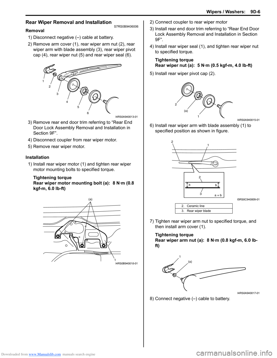
Removal1) Disconnect negative (–) cable at battery.
2) Remove arm cover (1), rear wiper arm nut (2), rear wiper arm with blade assembly (3), rear wiper pivot
cap (4), rear wiper nut (5) and rear wiper seal (6).
3) Remove rear end door trim referring to “Rear End Door Lock Assembly Remo val and Installation in
Section 9F”.
4) Disconnect coupler from rear wiper motor.
5) Remove rear wiper motor.
Installation 1) Install rear wiper motor (1) and tighten rear wiper motor mounting bolts to specified torque.
Tightening torque
Rear wiper motor mounting bolt (a): 8 N·m (0.8
kgf-m, 6.0 lb-ft) 2) Connect coupler to rear wiper motor
3) Install rear end door trim referring to “Rear End Door
Lock Assembly Removal and Installation in Section
9F”.
4) Install rear wiper seal (1), and tighten rear wiper nut to specified torque.
Tightening torque
Rear wiper nut (a): 5 N·m (0.5 kgf-m, 4.0 lb-ft)
5) Install rear wiper pivot cap (2).
6) Install rear wiper arm with blade assembly (1) to specified position as shown in figure.
7) Tighten rear wiper arm nut to specified torque, and then install arm cover (1).
Tightening torque
Rear wiper arm nut (a): 8 N·m (0.8 kgf-m, 6.0 lb-
ft)
8) Connect negative (–) cable to battery.
1 2
3
4 5
6
I4RS0A940013-01
1
(a)I4RS0B940018-01
2. Ceramic line
3. Rear wiper blade
2
1
(a)
I4RS0A940015-01
1
2
3
2a = b
a
bI5RS0C940009-01
1
(a)
I4RS0A940017-01
Page 1328 of 1496
Downloaded from www.Manualslib.com manuals search engine 9E-1 Glass / Windows / Mirrors:
Body, Cab and Accessories
Glass / Windows / Mirrors
General Description
Rear End Door Window Defogger System DescriptionS7RS0B9501001
The rear end door window defogger is controlled by BCM. For the BCM description refer to “BCM General Description
in Section 10B”.
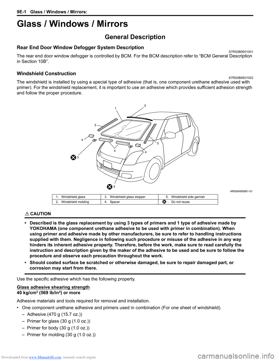
Windshield ConstructionS7RS0B9501002
The windshield is installed by using a special type of adhesive (that is, one component urethane adhesive used with
primer). For the windshield replacement, it is important to use an adhesive which provides sufficient adhesion strength
and follow the proper procedure.
CAUTION!
• Described is the glass replacement by using 3 types of primers and 1 type of adhesive made by YOKOHAMA (one component urethane adhesive to be used with primer in combination). When
using primer and adhesive made by other manufacturers, be sure to refer to handling instructions
supplied with them. Negligence in following such procedure or misuse of the adhesive in any way
hinders its inherent adhesive property. Therefore, before the work, make sure to read carefully the
instruction and description given by the maker of the adhesive to be used and be sure to follow the
procedure and observe each precaution throughout the work.
• Should coated surface be scratched or otherwise damaged, be sure to repair damaged part, or corrosion may start from there.
Use the specific adhesive which has the following property.
Glass adhesive shearing strength
40 kg/cm2 (569 lb/in2) or more
Adhesive materials and tools required for removal and installation.
• One component urethane adhesive and primers used in combination (For one sheet of windshield). – Adhesive (470 g (15.7 oz.))
– Primer for glass (30 g (1.0 oz.))
– Primer for body (30 g (1.0 oz.))
– Primer for molding (30 g (1.0 oz.))
3
3 1
2
44
4
5
5
I4RS0A950001-01
1. Windshield glass
3. Windshield glass stopper 5. Windshield side garnish
2. Windshield molding 4. Spacer : Do not reuse.
Page 1329 of 1496
Downloaded from www.Manualslib.com manuals search engine Glass / Windows / Mirrors: 9E-2
• Eyeleteer
• Piano string
• Windshield knife
• Brush for primer application (2 pcs)
•Knife
• Rubber sucker grip
• Sealant gun (for filling adhesive)
• Putty spatula (for correcting adhered parts)
Diagnostic Information and Procedures
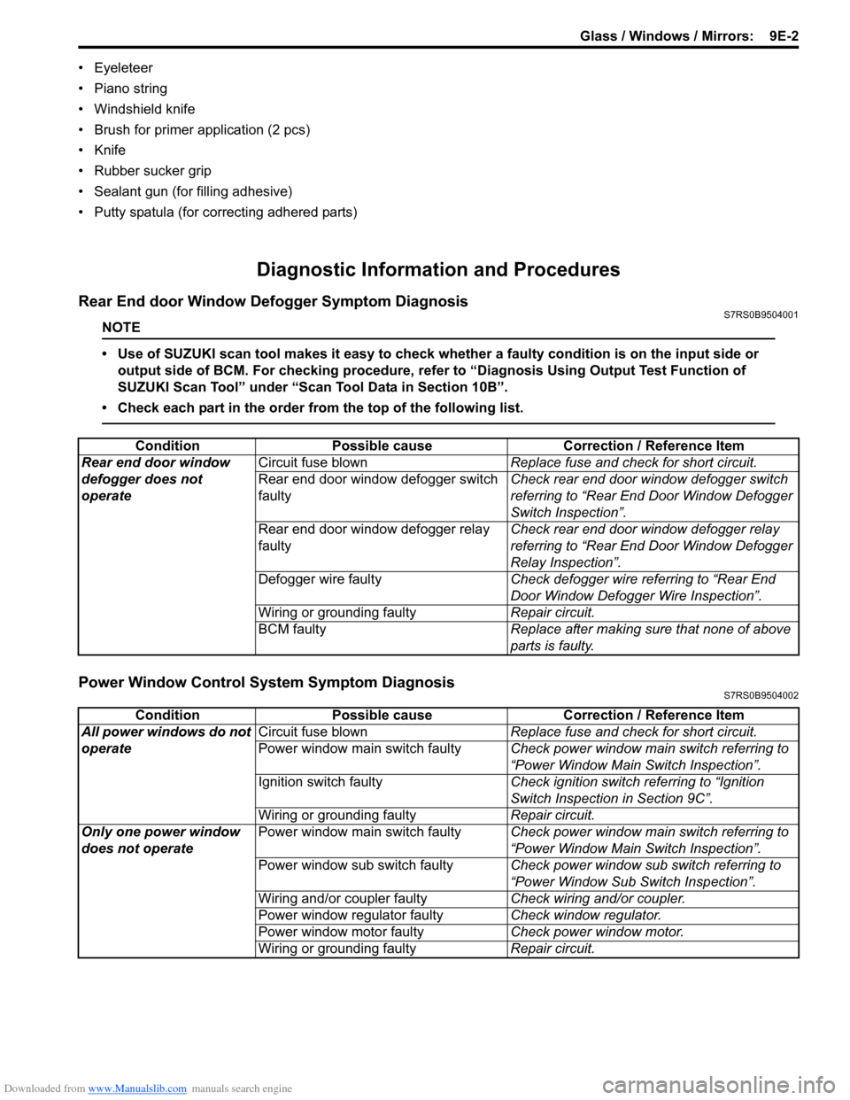
Rear End door Window Defogger Symptom DiagnosisS7RS0B9504001
NOTE
• Use of SUZUKI scan tool makes it easy to check whether a faulty condition is on the input side or
output side of BCM. For checking procedure, re fer to “Diagnosis Using Output Test Function of
SUZUKI Scan Tool” under “Scan Tool Data in Section 10B”.
• Check each part in the order from the top of the following list.
Power Window Control System Symptom DiagnosisS7RS0B9504002
Condition Possible cause Correction / Reference Item
Rear end door window
defogger does not
operate Circuit fuse blown
Replace fuse and check for short circuit.
Rear end door window defogger switch
faulty Check rear end door window defogger switch
referring to “Rear End Door Window Defogger
Switch Inspection”.
Rear end door window defogger relay
faulty Check rear end door window defogger relay
referring to “Rear End Door Window Defogger
Relay Inspection”.
Defogger wire faulty Check defogger wire referring to “Rear End
Door Window Defogger Wire Inspection”.
Wiring or grounding faulty Repair circuit.
BCM faulty Replace after making sure that none of above
parts is faulty.
ConditionPossible cause Correction / Reference Item
All power windows do not
operate Circuit fuse blown
Replace fuse and check for short circuit.
Power window main switch faulty Check power window main switch referring to
“Power Window Main Switch Inspection”.
Ignition switch faulty Check ignition switch referring to “Ignition
Switch Inspection in Section 9C”.
Wiring or grounding faulty Repair circuit.
Only one power window
does not operate Power window main switch faulty
Check power window main switch referring to
“Power Window Main Switch Inspection”.
Power window sub switch faulty Check power window sub switch referring to
“Power Window Sub Switch Inspection”.
Wiring and/or coupler faulty Check wiring and/or coupler.
Power window regulator faulty Check window regulator.
Power window motor faulty Check power window motor.
Wiring or grounding faulty Repair circuit.