Circuit SUZUKI SWIFT 2006 2.G Service Workshop Manual
[x] Cancel search | Manufacturer: SUZUKI, Model Year: 2006, Model line: SWIFT, Model: SUZUKI SWIFT 2006 2.GPages: 1496, PDF Size: 34.44 MB
Page 726 of 1496
Downloaded from www.Manualslib.com manuals search engine 5A-82 Automatic Transmission/Transaxle:
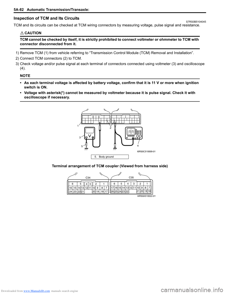
Inspection of TCM and Its CircuitsS7RS0B5104045
TCM and its circuits can be checked at TCM wiring connec tors by measuring voltage, pulse signal and resistance.
CAUTION!
TCM cannot be checked by itself, it is strictly prohibited to connect voltmeter or ohmmeter to TCM with
connector disconnected from it.
1) Remove TCM (1) from vehicle referring to “Transmission Control Module (TCM) Removal and Installation”.
2) Connect TCM connectors (2) to TCM.
3) Check voltage and/or pulse signal at each terminal of connectors connected using voltmeter (3) and oscilloscope
(4).
NOTE
• As each terminal voltage is affected by battery voltag e, confirm that it is 11 V or more when ignition
switch is ON.
• Voltage with asterisk(*) cannot be measured by voltmeter because it is pulse signal. Check it with oscilloscope if necessary.
Terminal arrangement of TCM coupler (Viewed from harness side)
5. Body ground
3
5 4
12
I6RS0C510009-01
65
16 15 14 13 12 11 43
24 23 2122 10 9 8 721
1920 18 17
C34
17 16
26 25
15 14
65 3
42
13 12
23 2224 11 10 9
21 20 19 87
18
1
C35
I4RS0A510022-01
Page 727 of 1496
Downloaded from www.Manualslib.com manuals search engine Automatic Transmission/Transaxle: 5A-83
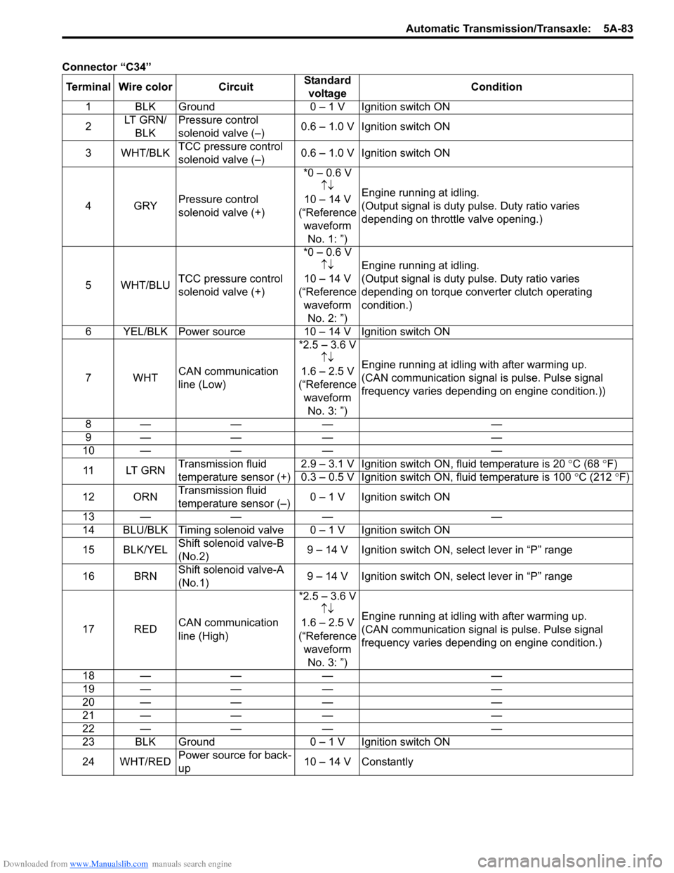
Connector “C34”Terminal Wire color Circuit Standard
voltage Condition
1 BLK Ground 0 – 1 V Ignition switch ON
2 LT GRN/
BLK Pressure control
solenoid valve (–)
0.6 – 1.0 V Ignition switch ON
3WHT/BLK TCC pressure control
solenoid valve (–) 0.6 – 1.0 V Ignition switch ON
4GRY Pressure control
solenoid valve (+) *0 – 0.6 V
↑↓
10 – 14 V
(“Reference waveform No. 1: ”) Engine running at idling.
(Output signal is duty pulse. Duty ratio varies
depending on throttle valve opening.)
5WHT/BLU TCC pressure control
solenoid valve (+) *0 – 0.6 V
↑↓
10 – 14 V
(“Reference waveform No. 2: ”) Engine running at idling.
(Output signal is duty pulse. Duty ratio varies
depending on torque converter clutch operating
condition.)
6 YEL/BLK Power source 10 – 14 V Ignition switch ON
7WHT CAN communication
line (Low) *2.5 – 3.6 V
↑↓
1.6 – 2.5 V
(“Reference waveform No. 3: ”) Engine running at idling with after warming up.
(CAN communication signal is pulse. Pulse signal
frequency varies depending on engine condition.))
8— — — —
9— — — —
10 — —— —
11 LT G R N Transmission fluid
temperature sensor (+) 2.9 – 3.1 V Ignition switch ON, fluid temperature is 20
°C (68 °F)
0.3 – 0.5 V Ignition switch ON, fluid temperature is 100 °C (212 °F)
12 ORN Transmission fluid
temperature sensor (–) 0 – 1 V Ignition switch ON
13 — —— —
14 BLU/BLK Timing solenoid valv e 0 – 1 V Ignition switch ON
15 BLK/YEL Shift solenoid valve-B
(No.2) 9 – 14 V Ignition switch ON, select lever in “P” range
16 BRN Shift solenoid valve-A
(No.1) 9 – 14 V Ignition switch ON, select lever in “P” range
17 RED CAN communication
line (High) *2.5 – 3.6 V
↑↓
1.6 – 2.5 V
(“Reference waveform No. 3: ”) Engine running at idling with after warming up.
(CAN communication signal is pulse. Pulse signal
frequency varies depending on engine condition.)
18 — —— —
19 — —— —
20 — —— —
21 — —— —
22 — —— —
23 BLK Ground 0 – 1 V Ignition switch ON
24 WHT/RED Power source
for back-
up 10 – 14 V Constantly
Page 728 of 1496
Downloaded from www.Manualslib.com manuals search engine 5A-84 Automatic Transmission/Transaxle:
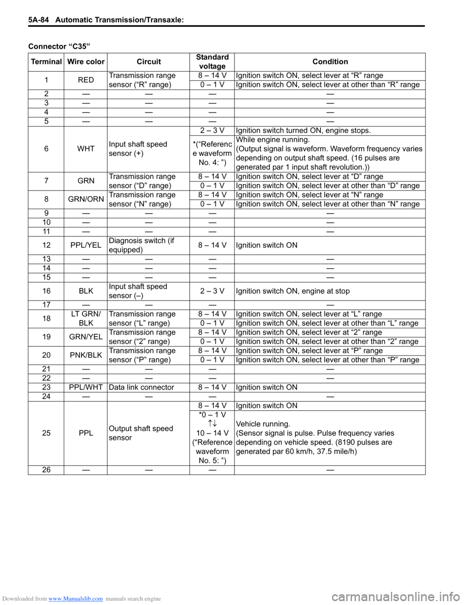
Connector “C35”
Terminal Wire color Circuit Standard
voltage Condition
1RED Transmission range
sensor (“R” range) 8 – 14 V Ignition switch ON, select lever at “R” range
0 – 1 V Ignition switch ON, select lever at other than “R” range
2— — — —
3— — — —
4— — — —
5— — — —
6WHT Input shaft speed
sensor (+) 2 – 3 V Ignition switch turned ON, engine stops.
*(“Referenc
e waveform No. 4: ”) While engine running.
(Output signal is waveform. Waveform frequency varies
depending on output shaft speed. (16 pulses are
generated par 1 input shaft revolution.))
7GRN Transmission range
sensor (“D” range) 8 – 14 V Ignition switch ON, select lever at “D” range
0 – 1 V Ignition switch ON, select lever at other than “D” range
8 GRN/ORN Transmission range
sensor (“N” range) 8 – 14 V Ignition switch ON, select lever at “N” range
0 – 1 V Ignition switch ON, select lever at other than “N” range
9— — — —
10 — — — — 11 — — — —
12 PPL/YEL Diagnosis switch (if
equipped) 8 – 14 V Ignition switch ON
13 — — — —
14 — — — —
15 — — — —
16 BLK Input shaft speed
sensor (–) 2 – 3 V Ignition switch ON, engine at stop
17 — — — —
18 LT G R N /
BLK Transmission range
sensor (“L” range) 8 – 14 V Ignition switch ON, select lever at “L” range
0 – 1 V Ignition switch ON, select lever at other than “L” range
19 GRN/YEL Transmission range
sensor (“2” range) 8 – 14 V Ignition switch ON, select lever at “2” range
0 – 1 V Ignition switch ON, select lever at other than “2” range
20 PNK/BLK Transmission range
sensor (“P” range) 8 – 14 V Ignition switch ON, select lever at “P” range
0 – 1 V Ignition switch ON, select lever at other than “P” range
21 — — — —
22 — — — —
23 PPL/WHT Data link connector 8 – 14 V Ignition switch ON
24 — — — —
25 PPL Output shaft speed
sensor 8 – 14 V Ignition switch ON
*0 – 1 V ↑↓
10 – 14 V
(“Reference waveform No. 5: ”) Vehicle running.
(Sensor signal is pulse. Pulse frequency varies
depending on vehicle speed. (8190 pulses are
generated par 60 km/h, 37.5 mile/h)
26 — — — —
Page 730 of 1496
Downloaded from www.Manualslib.com manuals search engine 5A-86 Automatic Transmission/Transaxle:
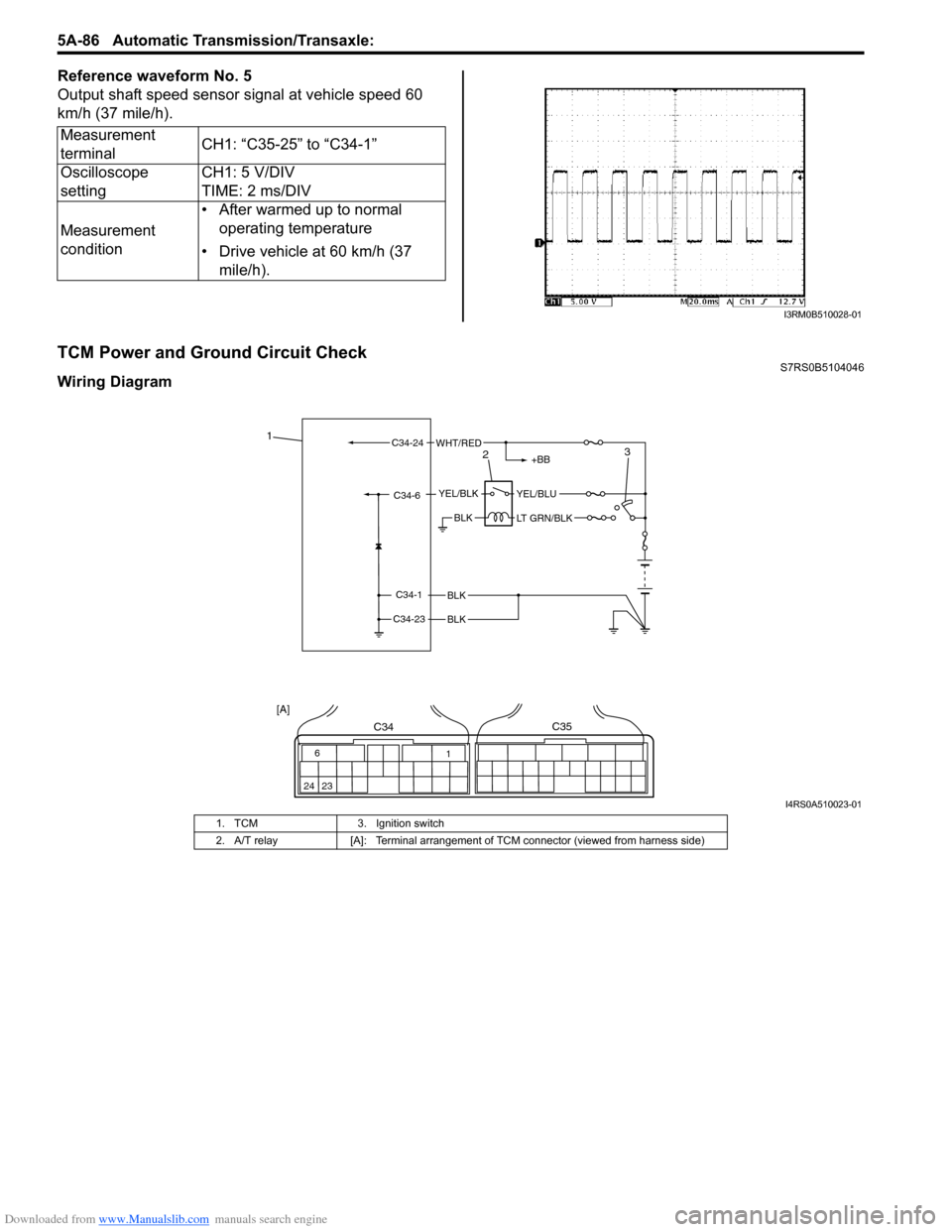
Reference waveform No. 5
Output shaft speed sensor signal at vehicle speed 60
km/h (37 mile/h).
TCM Power and Ground Circuit CheckS7RS0B5104046
Wiring DiagramMeasurement
terminal
CH1: “C35-25” to “C34-1”
Oscilloscope
setting CH1: 5 V/DIV
TIME: 2 ms/DIV
Measurement
condition • After warmed up to normal
operating temperature
• Drive vehicle at 60 km/h (37 mile/h).
I3RM0B510028-01
BLK
BLK
BLK
C34-1
C34-23
C34-6YEL/BLKYEL/BLU
LT GRN/BLK
+BB
C34-24WHT/RED1
23
6
24 23 1
C34C35
[A]
I4RS0A510023-01
1. TCM
3. Ignition switch
2. A/T relay [A]: Terminal arrangement of TCM connector (viewed from harness side)
Page 731 of 1496
Downloaded from www.Manualslib.com manuals search engine Automatic Transmission/Transaxle: 5A-87
Troubleshooting
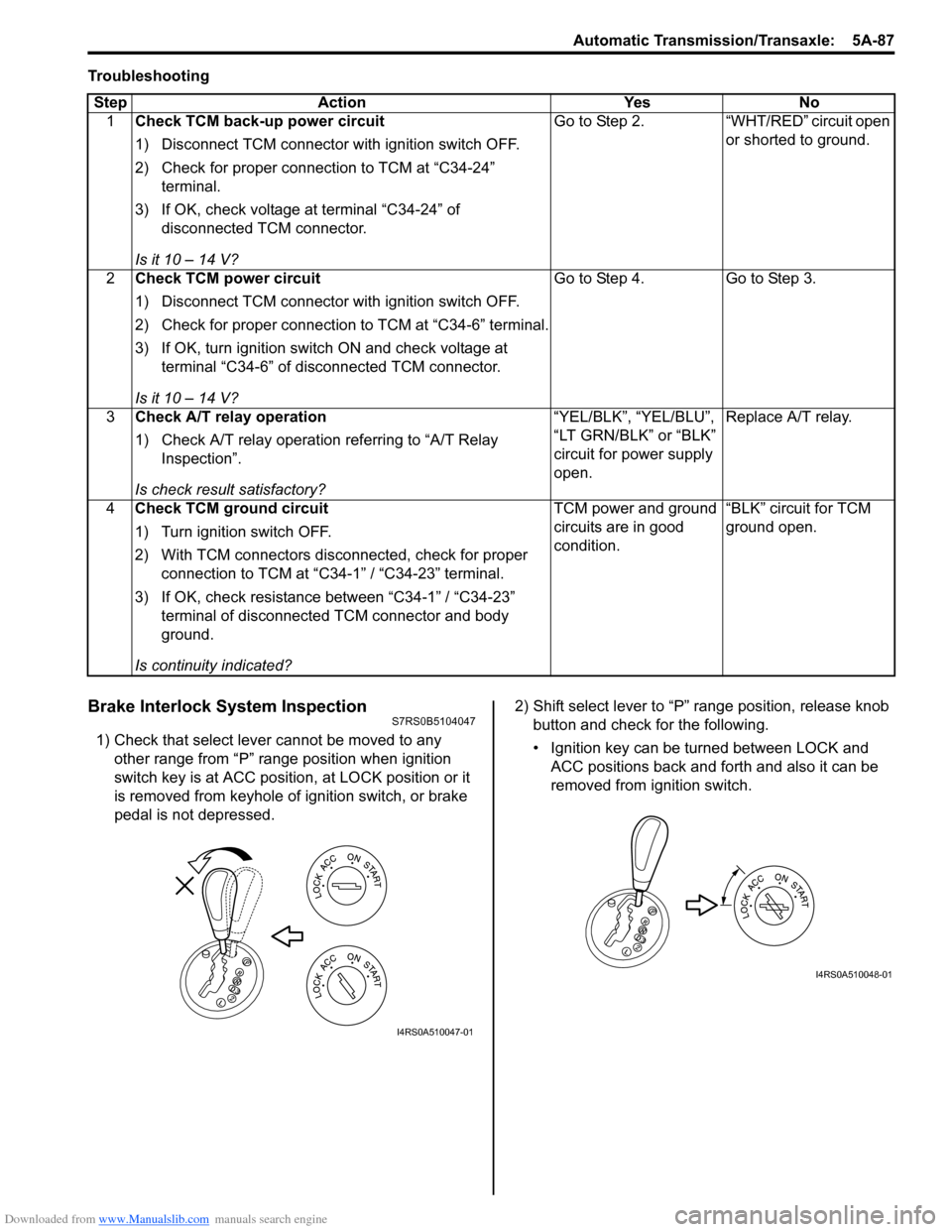
Brake Interlock System InspectionS7RS0B5104047
1) Check that select lever cannot be moved to any other range from “P” range position when ignition
switch key is at ACC position, at LOCK position or it
is removed from keyhole of ignition switch, or brake
pedal is not depressed. 2) Shift select lever to “P” range position, release knob
button and check for the following.
• Ignition key can be turned between LOCK and ACC positions back and forth and also it can be
removed from ignition switch.
Step Action Yes No
1 Check TCM back-up power circuit
1) Disconnect TCM connector with ignition switch OFF.
2) Check for proper connection to TCM at “C34-24”
terminal.
3) If OK, check voltage at terminal “C34-24” of disconnected TCM connector.
Is it 10 – 14 V? Go to Step 2. “WHT/RED” circuit open
or shorted to ground.
2 Check TCM power circuit
1) Disconnect TCM connector with ignition switch OFF.
2) Check for proper connection to TCM at “C34-6” terminal.
3) If OK, turn ignition switch ON and check voltage at
terminal “C34-6” of disconnected TCM connector.
Is it 10 – 14 V? Go to Step 4. Go to Step 3.
3 Check A/T relay operation
1) Check A/T relay operation referring to “A/T Relay
Inspection”.
Is check result satisfactory? “YEL/BLK”, “YEL/BLU”,
“LT GRN/BLK” or “BLK”
circuit for power supply
open.
Replace A/T relay.
4 Check TCM ground circuit
1) Turn ignition switch OFF.
2) With TCM connectors disconnected, check for proper
connection to TCM at “C34-1” / “C34-23” terminal.
3) If OK, check resistance between “C34-1” / “C34-23” terminal of disconnected TCM connector and body
ground.
Is continuity indicated? TCM power and ground
circuits are in good
condition.
“BLK” circuit for TCM
ground open.
I4RS0A510047-01
I4RS0A510048-01
Page 867 of 1496

Downloaded from www.Manualslib.com manuals search engine Table of Contents 6- i
6
Section 6
CONTENTS
Steering
Precautions ................................................. 6-1
Precautions............................................................. 6-1
Precautions on Steering........................................ 6-1
Steering General Diagnosi s.................... 6A-1
Precautions........................................................... 6A-1
Precautions for Steering Diagnosis ..................... 6A-1
Diagnostic Information and Procedures ............ 6A-2 Steering Symptom Diagnosis .............................. 6A-2
Steering Wheel and Column ................... 6B-1
Precautions........................................................... 6B-1
Service Precautions of Steering Wheel and Column.............................................................. 6B-1
General Description ............................................. 6B-1 Steering Wheel and Column Construction .......... 6B-1
Diagnostic Information and Procedures ............ 6B-2 Checking Steering Column for Accident Damage ............................................................ 6B-2
Repair Instructions .............................................. 6B-3 Steering Wheel and Column Construction .......... 6B-3
Steering Wheel Removal and Installation ........... 6B-4
Contact Coil Cable Assembly Removal and Installation ......................................................... 6B-5
Centering Contact Coil Cable Assembly ............. 6B-6
Contact Coil Cable Assembly Inspection ............ 6B-6
Steering Angle Sensor Removal and Installation ......................................................... 6B-6
Steering Angle Sensor Inspection ....................... 6B-6
Steering Column Removal and Installation ......... 6B-7
Steering Column Inspecti on ................................ 6B-8
Ignition Switch Cylinder Assembly Removal and Installation (Non- Keyless Start Model)...... 6B-9
Steering Lock Assembly (Ignition Switch) Removal and Installation................................... 6B-9
Steering Lower Shaft Removal and Installation ....................................................... 6B-10
Specifications ..................................................... 6B-11
Tightening Torque Specifications ...................... 6B-11
Special Tools and Equipmen t ........................... 6B-11
Special Tool ...................................................... 6B-11
Power Assisted Steering System........... 6C-1
Precautions........................................................... 6C-1 Steering System Note .........................................6C-1
Precautions in Diagnosing Troubles ...................6C-1
General Description .............................................6C-2 P/S System Description ......................................6C-2
EPS Diagnosis General Descr iption ...................6C-3
On-Board Diagnostic System Description ...........6C-3
Schematic and Routing Diagram ........................6C-4 EPS System Wiring Circuit Diagram ...................6C-4
Diagnostic Information and Procedures ............6C-5 EPS System Check .............. ...............................6C-5
“EPS” Warning Light Check . ...............................6C-8
DTC Check..........................................................6C-8
DTC Clearance ...................................................6C-9
DTC Table ...........................................................6C-9
Scan Tool Data .................................................6C-11
Visual Inspection ...............................................6C-12
P/S System Symptom Diagnosis ......................6C-12
Serial Data Link Circuit Check ..........................6C-13
“EPS” Warning Light Do es Not Come ON with
Ignition Switch Turn ed ON before Engine
Starts ...............................................................6C-15
“EPS” Warning Light Remains ON Steady after Engine Starts ..........................................6C-16
DTC C1113: Steering Torque Sensor (Main and Sub) Circuit Correlation ............................6C-17
DTC C1114: Steering Torque Sensor Reference Power Supply Circuit .....................6C-19
DTC C1117: Steering Torque Sensor Failure Signal Circuit Low ...........................................6C-21
DTC C1118: Steering Torque Sensor Failure Signal Circuit High...........................................6C-22
DTC C1119: Steering Torque Sensor Power Supply Circuit ..................................................6C-24
DTC C1121 / C1123 / C1124: VSS Circuit
Failure .............................................................6C-26
DTC C1122: Engine Speed Signal....................6C-28
DTC C1141 / C1142 / C1143 / C1145: P/S Motor Circuit Failure ........................................6C-30
DTC C1153: P/S Control Module Power Supply Circuit Voltage Low .............................6C-32
DTC C1155: P/S Control Module Failure ..........6C-33
P/S Control Module Power Supply and Ground Circuit Check ......................................6C-34
Inspection of P/S Control Module and Its Circuits ............................................................6C-35
Page 868 of 1496
Downloaded from www.Manualslib.com manuals search engine 6-ii Table of Contents
Steering Wheel Play Check ..............................6C-39
Steering Force Check .......................................6C-39
Repair Instructions ........... .................................6C-40
Steering Gear Case Assembly Components ....6C-40
Tie-Rod End Boot On-Vehic le Inspection .........6C-41
Tie-Rod End Removal and Installation..............6C-41
Tie-Rod End Inspection.....................................6C-42
Steering Shaft Joint On-Vehicle Inspection.......6C-42
Steering Gear Case Assembly Removal and Installation .......................................................6C-42
Steering Rack Boot Inspec tion ..........................6C-43
Tie-Rod / Rack Boot Removal and Installation ..6C-43 Steering Rack Plunger Removal and
Installation .......................................................6C-45
Steering Rack Plunger Inspection .....................6C-45
P/S Control Module Removal and Installation...6C-46
Torque Sensor and Its Circuit Inspection ..........6C-46
P/S Motor and Its Circuit Inspection ..................6C-47
Specifications ..................... ................................6C-48
Tightening Torque Specifications ......................6C-48
Special Tools and Equipmen t ...........................6C-49
Recommended Service Material .......................6C-49
Special Tool ......................................................6C-49
Page 877 of 1496
Downloaded from www.Manualslib.com manuals search engine Steering Wheel and Column: 6B-6
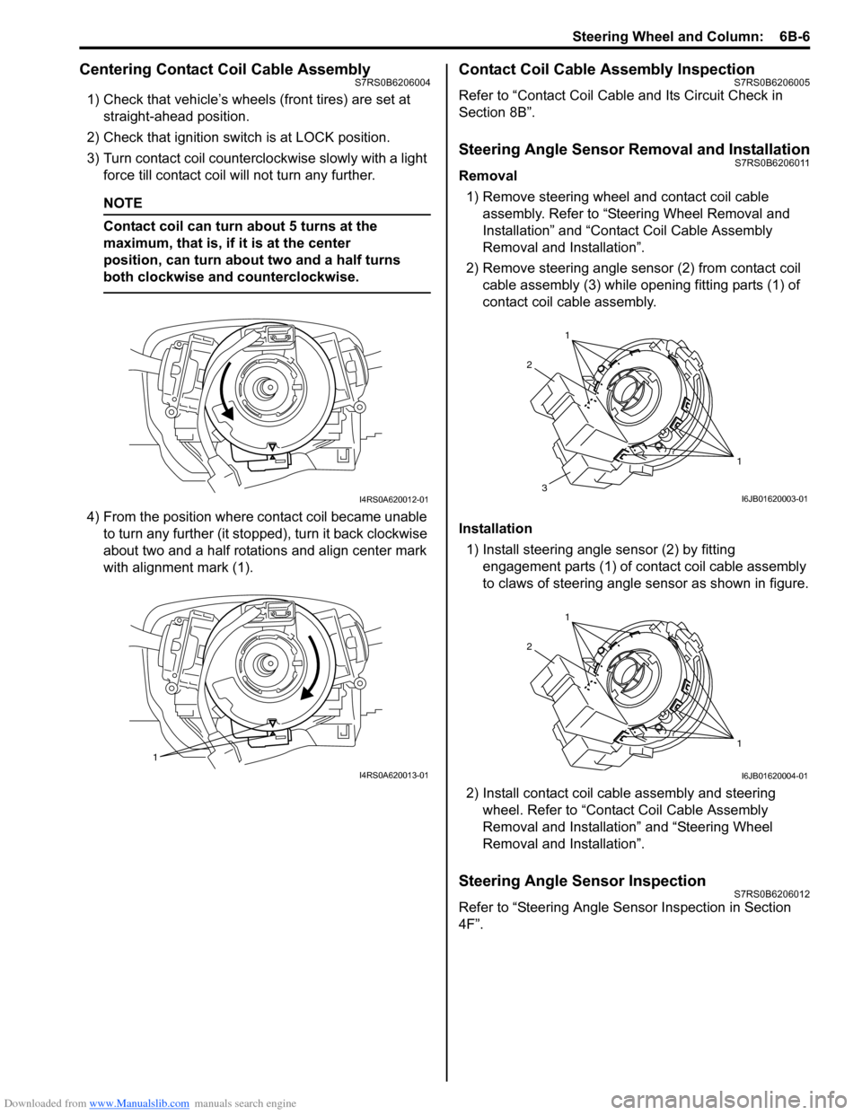
Centering Contact Coil Cable AssemblyS7RS0B6206004
1) Check that vehicle’s wheels (front tires) are set at straight-ahead position.
2) Check that ignition swit ch is at LOCK position.
3) Turn contact coil counterclockwise slowly with a light force till contact coil will not turn any further.
NOTE
Contact coil can turn about 5 turns at the
maximum, that is, if it is at the center
position, can turn about two and a half turns
both clockwise and counterclockwise.
4) From the position where contact coil became unable to turn any further (it stopped), turn it back clockwise
about two and a half rotations and align center mark
with alignment mark (1).
Contact Coil Cable Assembly InspectionS7RS0B6206005
Refer to “Contact Coil Cable and Its Circuit Check in
Section 8B”.
Steering Angle Sensor Removal and InstallationS7RS0B6206011
Removal
1) Remove steering wheel and contact coil cable assembly. Refer to “Ste ering Wheel Removal and
Installation” and “Contact Coil Cable Assembly
Removal and Installation”.
2) Remove steering angle sensor (2) from contact coil cable assembly (3) while op ening fitting parts (1) of
contact coil cable assembly.
Installation 1) Install steering angle sensor (2) by fitting engagement parts (1) of contact coil cable assembly
to claws of steering angle sensor as shown in figure.
2) Install contact coil cable assembly and steering wheel. Refer to “Contact Coil Cable Assembly
Removal and Installation” and “Steering Wheel
Removal and Installation”.
Steering Angle Sensor InspectionS7RS0B6206012
Refer to “Steering Angle Sens or Inspection in Section
4F”.
I4RS0A620012-01
1
I4RS0A620013-01
1
1
2
3I6JB01620003-01
1
1
2
I6JB01620004-01
Page 883 of 1496
Downloaded from www.Manualslib.com manuals search engine Power Assisted Steering System: 6C-1
Steeri ng
Power Assisted Steering System
Precautions
Steering System NoteS7RS0B6300001
NOTE
All steering gear fasteners are important attaching parts in that they could affect the performance of
vital parts and systems, and/or could result in major repair expense. They must be replaced with one of
the same part number or with an equivalent part if replacement becomes necessary. Do not use a
replacement part of lesser quality or substitute design. Torque values must be used as specified
during reassembly to assure proper retention of these parts.
Precautions in Diagnosing TroublesS7RS0B6300002
• Take a note of DTC indicated on the SUZUKI scan tool.
• Before inspection, be sure to read “Pre cautions for Electrical Circuit Service in Section 00” and understand what is
written there.
• DTC C1122 (engine speed signal failure) is indicated when ignition switch is at ON position and engine is not
running, but it means there is nothing abnormal if indica tion changes to a normal one when engine is started.
• As DTC is stored in memory of the P/S control module, be sure to clear memory after repair by performing the
procedure described in “DTC Clearance”.
Page 886 of 1496
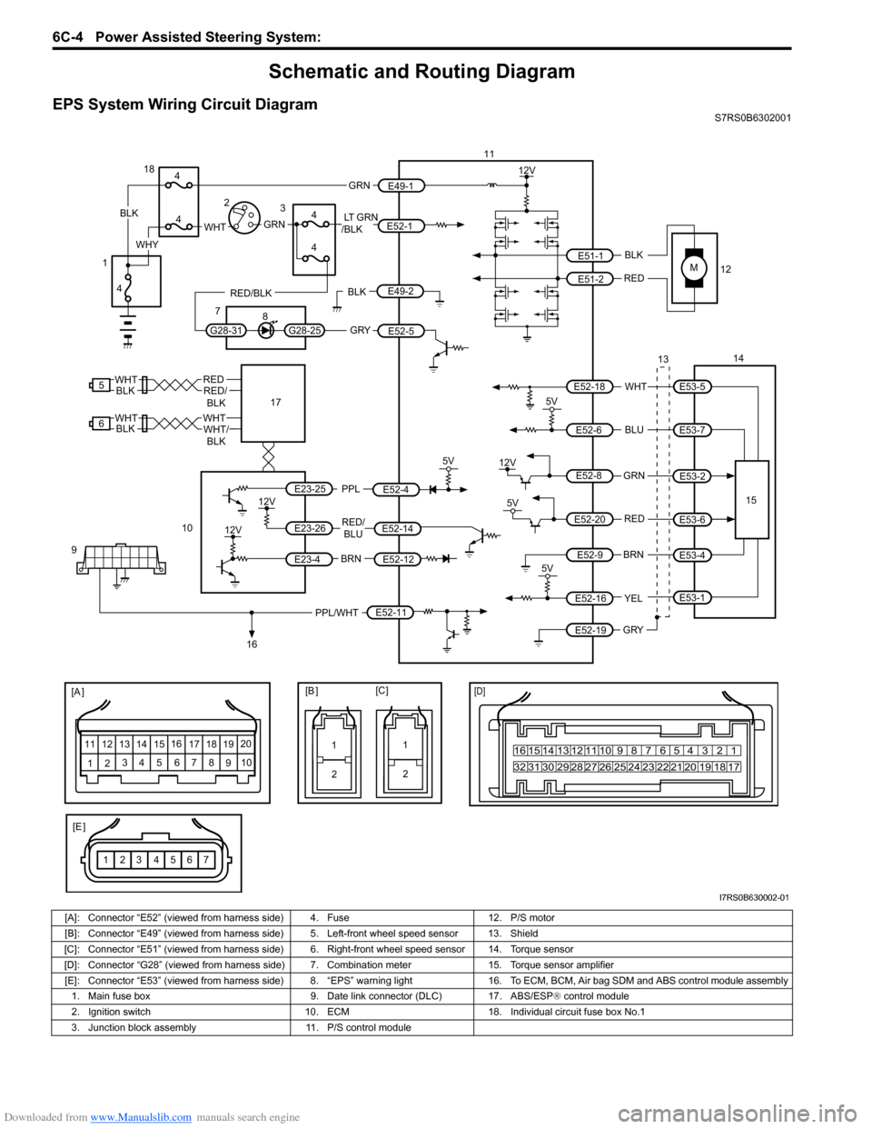
Downloaded from www.Manualslib.com manuals search engine 6C-4 Power Assisted Steering System:
Schematic and Routing Diagram
EPS System Wiring Circuit DiagramS7RS0B6302001
M
5V
BRNRED/
BLU
BLK
RED
WHT
BLU
GRN
BRN YEL
E52-11
E52-14E52-12
E23-4
E23-26
E23-25 E51-1
E51-2
E52-18
E53-5
E53-7
E52-6
E52-8
E53-2
E52-9
E52-16
E52-19
GRY
PPL/WHT
[A ]
[E ]
12 3
4 5 67
89
11
10
12 13
141516
17 18 19 20
1
2
[B ][C ]
1210 9 8 7654 3 21
16 15 14 13 12 11
26 25 24 2322 21 20 19 18 17
32 31 30 29 28 27
[D]
5V
PPL
E52-4
11
12
13 14
15
10
9
16
12V
5V
5V
12V
REDE52-20E53-6
E53-4
E53-1
7654321
5
REDRED/
BLKWHT
6WHTWHT/BLKWHTBLK
12V
12V
17BLK
GRY
LT GRN
/BLK
E52-1
E52-5
E49-1
GRNGRNWHTBLK
WHY
G28-25G28-31
RED/BLK
18
3
4
4
7 8
4
4
1 2
4
E49-2BLK
I7RS0B630002-01
[A]: Connector “E52” (viewed from harness side) 4. Fuse 12. P/S motor
[B]: Connector “E49” (viewed from harness side ) 5. Left-front wheel speed sensor 13. Shield
[C]: Connector “E51” (viewed from harness side) 6 . Right-front wheel speed sensor 14. Torque sensor
[D]: Connector “G28” (viewed from harness side) 7. Combination meter 15. Torque sensor amplifier
[E]: Connector “E53” (viewed from harness side) 8. “EPS” warning light16. To ECM, BCM, Air bag SDM and ABS control module assembly
1. Main fuse box 9. Date link connector (DLC) 17. ABS/ESP ® control module
2. Ignition switch 10. ECM18. Individual circuit fuse box No.1
3. Junction block assembly 11. P/S control module