Information SUZUKI SWIFT 2006 2.G Service Workshop Manual
[x] Cancel search | Manufacturer: SUZUKI, Model Year: 2006, Model line: SWIFT, Model: SUZUKI SWIFT 2006 2.GPages: 1496, PDF Size: 34.44 MB
Page 1412 of 1496
Downloaded from www.Manualslib.com manuals search engine 10B-9 Body Electrical Control System:
Diagnostic Information and Procedures
BCM Self-Diagnosis FunctionS7RS0BA204001
• BCM monitors conditions of the system components and its circuit with ignition switch turned to ON position. When
an abnormality in the system oc curs, the area where that abnormality lies is stored in the memory of EEPROM in
BCM.
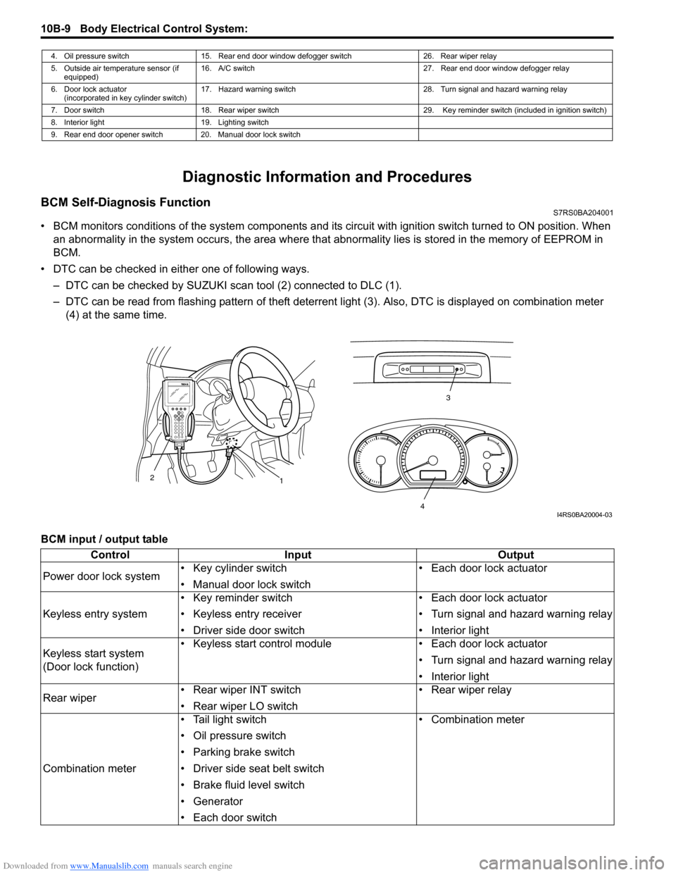
• DTC can be checked in either one of following ways. – DTC can be checked by SUZUKI scan tool (2) connected to DLC (1).
– DTC can be read from flashing pattern of theft deterrent light (3). Also, DTC is displayed on combination meter
(4) at the same time.
BCM input / output table
4. Oil pressure switch 15. Rear end door window defogger switch 26. Rear wiper relay
5. Outside air temperature sensor (if equipped) 16. A/C switch
27. Rear end door window defogger relay
6. Door lock actuator (incorporated in key cylinder switch) 17. Hazard warning switch
28. Turn signal and hazard warning relay
7. Door switch 18. Rear wiper switch 29. Key reminder switch (included in ignition switch)
8. Interior light 19. Lighting switch
9. Rear end door opener switch 20. Manual door lock switch
3
1
2
4I4RS0BA20004-03
Control
Input Output
Power door lock system • Key cylinder switch
• Manual door lock switch • Each door lock actuator
Keyless entry system • Key reminder switch
• Keyless entry receiver
• Driver side door switch • Each door lock actuator
• Turn signal and hazard warning relay
• Interior light
Keyless start system
(Door lock function) • Keyless start control module
• Each door lock actuator
• Turn signal and hazard warning relay
• Interior light
Rear wiper • Rear wiper INT switch
• Rear wiper LO switch • Rear wiper relay
Combination meter • Tail light switch
• Oil pressure switch
• Parking brake switch
• Driver side seat belt switch
• Brake fluid level switch
• Generator
• Each door switch • Combination meter
Page 1413 of 1496
Downloaded from www.Manualslib.com manuals search engine Body Electrical Control System: 10B-10
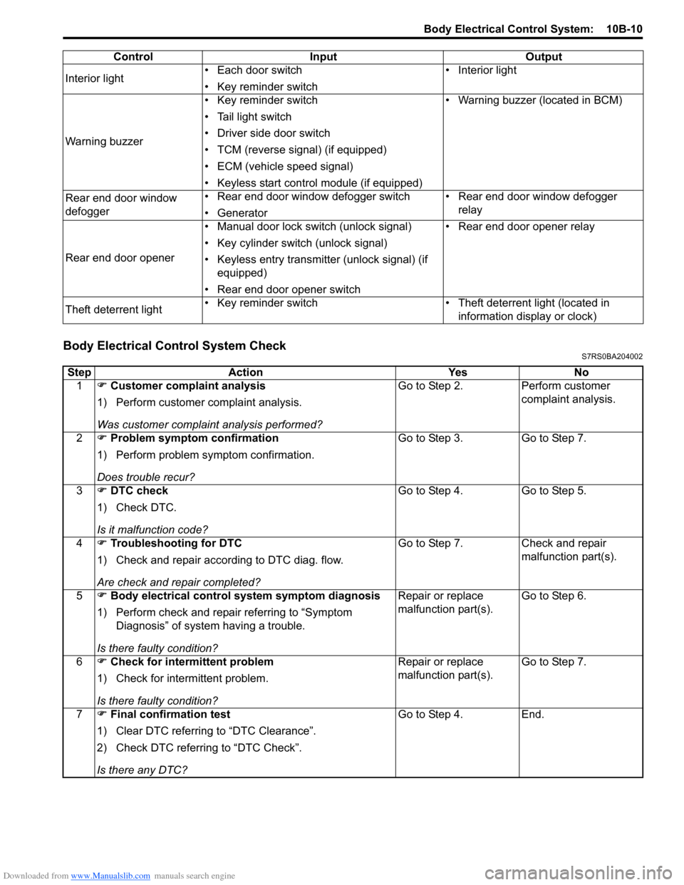
Body Electrical Control System CheckS7RS0BA204002
Interior light• Each door switch
• Key reminder switch • Interior light
Warning buzzer • Key reminder switch
• Tail light switch
• Driver side door switch
• TCM (reverse signal) (if equipped)
• ECM (vehicle speed signal)
• Keyless start control module (if equipped) • Warning buzzer (located in BCM)
Rear end door window
defogger • Rear end door window defogger switch
• Generator • Rear end door window defogger
relay
Rear end door opener • Manual door lock switch (unlock signal)
• Key cylinder switch (unlock signal)
• Keyless entry transmitter (unlock signal) (if
equipped)
• Rear end door opener switch • Rear end door opener relay
Theft deterrent light • Key reminder switch • Theft deterrent light (located in
information display or clock)
Control Input Output
Step
Action YesNo
1 �) Customer complaint analysis
1) Perform customer complaint analysis.
Was customer complaint analysis performed? Go to Step 2.
Perform customer
complaint analysis.
2 �) Problem symptom confirmation
1) Perform problem symptom confirmation.
Does trouble recur? Go to Step 3.
Go to Step 7.
3 �) DTC check
1) Check DTC.
Is it malfunction code? Go to Step 4.
Go to Step 5.
4 �) Troubleshooting for DTC
1) Check and repair according to DTC diag. flow.
Are check and repair completed? Go to Step 7.
Check and repair
malfunction part(s).
5 �) Body electrical control system symptom diagnosis
1) Perform check and repair referring to “Symptom Diagnosis” of system having a trouble.
Is there faulty condition? Repair or replace
malfunction part(s).
Go to Step 6.
6 �) Check for intermittent problem
1) Check for interm ittent problem.
Is there faulty condition? Repair or replace
malfunction part(s).
Go to Step 7.
7 �) Final confirmation test
1) Clear DTC referring to “DTC Clearance”.
2) Check DTC referring to “DTC Check”.
Is there any DTC? Go to Step 4.
End.
Page 1414 of 1496
Downloaded from www.Manualslib.com manuals search engine 10B-11 Body Electrical Control System:
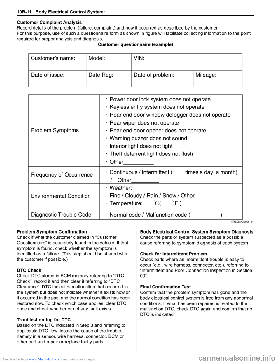
Customer Complaint Analysis
Record details of the problem (failure, complaint) and how it occurred as described by the customer.
For this purpose, use of such a questionnaire form as shown in figure will facilitate collectin g information to the point
required for proper analysis and diagnosis. Customer questionnaire (example)
Problem Symptom Confirmation
Check if what the custom er claimed in “Customer
Questionnaire” is accurately f ound in the vehicle. If that
symptom is found, check whether the symptom is
identified as a failure. (This step should be shared with
the customer if possible.)
DTC Check
Check DTC stored in BCM me mory referring to “DTC
Check”, record it and then clear it referring to “DTC
Clearance”. DTC indicates malfunction that occurred in
the system but does not indicate whether it exists now or
it occurred in the past and the normal condition has been
restored now. To check which case applies, clear DTC
once and check whether or not any fault exists.
Troubleshooting for DTC
Based on the DTC indicated in Step 3 and referring to
applicable DTC flow, locate the cause of the trouble,
namely in a sensor, wire harness, connector, BCM or
other part and repair or replace faulty parts. Body Electrical Control System Symptom Diagnosis
Check the parts or system
suspected as a possible
cause referring to symptom diagnosis of each system.
Check for Intermi ttent Problem
Check parts where an intermit tent trouble is easy to
occur (e.g., wire harness, connector, etc.), referring to
“Intermittent and Poor Connec tion Inspection in Section
00”.
Final Confirmation Test
Confirm that the problem symptom has gone and the
body electrical control system is free from any abnormal
conditions. If what has been repaired is related to the
malfunction DTC, check DTC again and confirm that no
DTC is indicated.
Customers name:
Model:
VIN:
Date of issue:
Date Reg:
Date of problem:
Mileage:
Problem Symptoms
Power door lock system does not operate
Keyless entry system does not operate
Rear end door window defogger does not operate
Rear wiper does not operate
Rear end door opener does not operate
Other
Frequency of Occurrence
Continuous / Intermittent ( times a day, a month)
/ Other
Environmental Condition
Weather:
Fine / Cloudy / Rain / Snow / Other
Temperature: (F )
Diagnostic Trouble Code Normal code / Malfunction code ( )
Warning buzzer does not sound
Interior light does not light
Theft deterrent light does not flush
I5RS0DA20006-01
Page 1416 of 1496
Downloaded from www.Manualslib.com manuals search engine 10B-13 Body Electrical Control System:
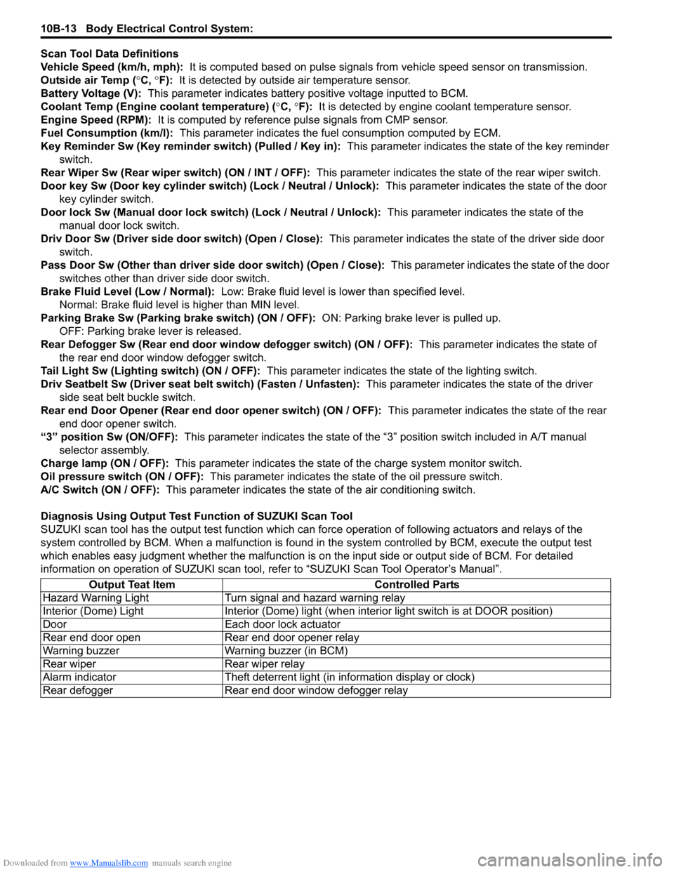
Scan Tool Data Definitions
Vehicle Speed (km/h, mph): It is computed based on pulse signals from vehicle speed sensor on transmission.
Outside air Temp ( °C, °F): It is detected by outside air temperature sensor.
Battery Voltage (V): This parameter indicates battery po sitive voltage inputted to BCM.
Coolant Temp (Engine coolant temperature) ( °C, °F): It is detected by engine coolant temperature sensor.
Engine Speed (RPM): It is computed by reference pulse signals from CMP sensor.
Fuel Consumption (km/l): This parameter indicates the fuel consumption computed by ECM.
Key Reminder Sw (Key reminder switch) (Pulled / Key in): This parameter indicates the state of the key reminder
switch.
Rear Wiper Sw (Rear wiper switch) (ON / INT / OFF): This parameter indicates the state of the rear wiper switch.
Door key Sw (Door key cylinder switch) (Lock / Neutral / Unlock): This parameter indicates the state of the door
key cylinder switch.
Door lock Sw (Manual door lock switch) (Lock / Neutral / Unlock): This parameter indicates the state of the
manual door lock switch.
Driv Door Sw (Driver side d oor switch) (Open / Close): This parameter indicates the state of the driver side door
switch.
Pass Door Sw (Other than driver side door switch) (Open / Close): This parameter indicates the state of the door
switches other than driver side door switch.
Brake Fluid Level (Low / Normal): Low: Brake fluid level is lower than specified level.
Normal: Brake fluid level is higher than MIN level.
Parking Brake Sw (Parking brake switch) (ON / OFF): ON: Parking brake lever is pulled up.
OFF: Parking brake lever is released.
Rear Defogger Sw (Rear end door window defogger switch) (ON / OFF): This parameter indicates the state of
the rear end door window defogger switch.
Tail Light Sw (Lighting switch) (ON / OFF): This parameter indicates the state of the lighting switch.
Driv Seatbelt Sw (Driver seat belt switch) (Fasten / Unfasten): This parameter indicates the state of the driver
side seat belt buckle switch.
Rear end Door Opener (Rear end door opener switch) (ON / OFF): This parameter indicates the state of the rear
end door opener switch.
“3” position Sw (ON/OFF): This parameter indicates the state of the “3 ” position switch included in A/T manual
selector assembly.
Charge lamp (ON / OFF): This parameter indicates the state of the charge system monitor switch.
Oil pressure switch (ON / OFF): This parameter indicates the state of the oil pressure switch.
A/C Switch (ON / OFF): This parameter indicates the state of the air conditioning switch.
Diagnosis Using Output Test Function of SUZUKI Scan Tool
SUZUKI scan tool has the output test function which can force operation of following actuators and relays of the
system controlled by BCM. When a malf unction is found in the system controlled by BCM, execute the output test
which enables easy judgment whether the malfunction is on the input side or output side of BCM. For detailed
information on operation of SUZUKI scan tool, refer to “SUZUKI Scan Tool Operator’s Manual”.
Output Teat Item Controlled Parts
Hazard Warning Light Turn signal and hazard warning relay
Interior (Dome) Light Interior (Dome) light (wh en interior light switch is at DOOR position)
Door Each door lock actuator
Rear end door open Rear end door opener relay
Warning buzzer Warning buzzer (in BCM)
Rear wiper Rear wiper relay
Alarm indicator Theft deterrent light (in information display or clock)
Rear defogger Rear end door window defogger relay
Page 1436 of 1496
Downloaded from www.Manualslib.com manuals search engine 10B-33 Body Electrical Control System:
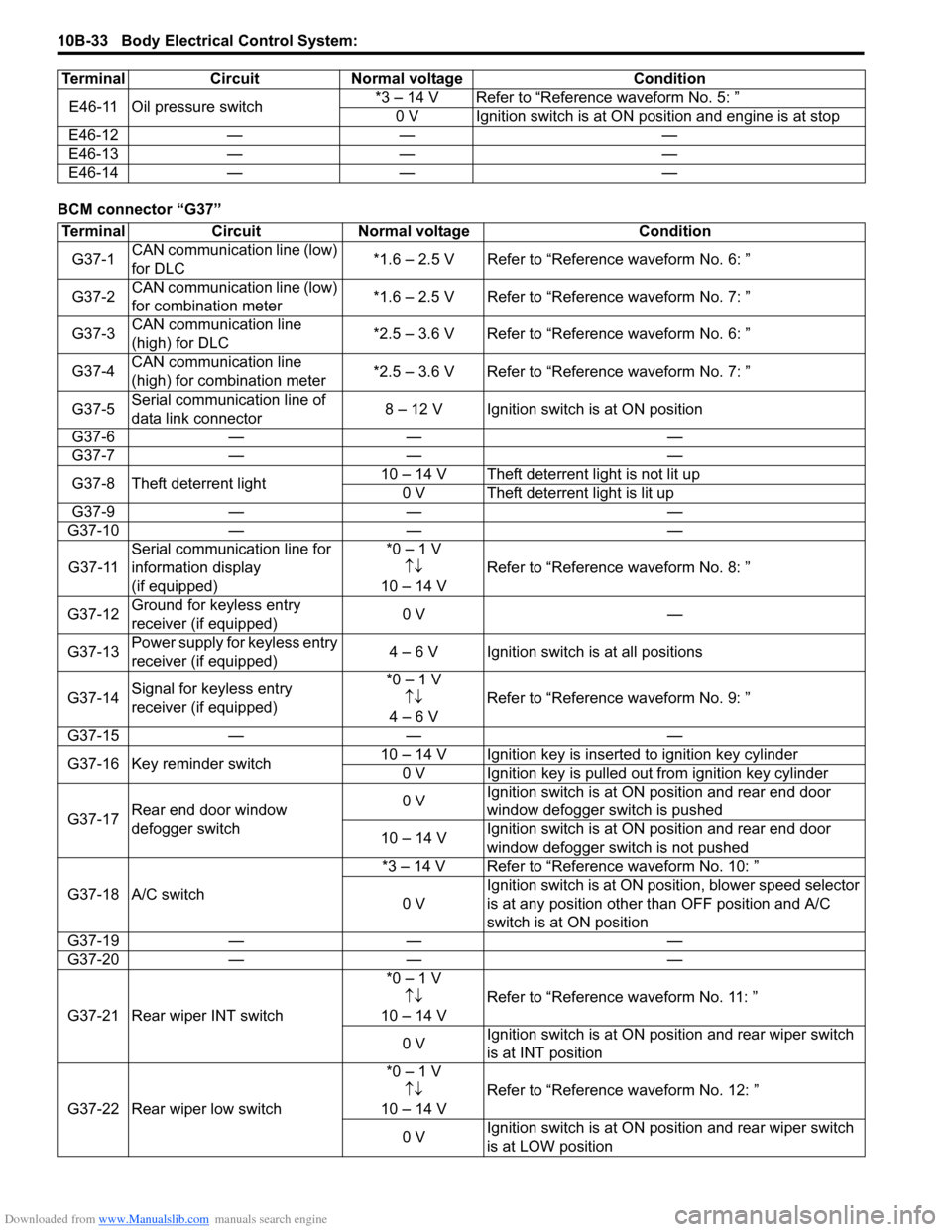
BCM connector “G37”E46-11 Oil pressure switch
*3 – 14 V Refer to “Reference waveform No. 5: ”
0 V Ignition switch is at ON position and engine is at stop
E46-12 — — —
E46-13 — — —
E46-14 — — —
Terminal Circuit Normal voltage Condition
Terminal
CircuitNormal voltage Condition
G37-1 CAN communication line (low)
for DLC *1.6 – 2.5 V Refer to “Reference waveform No. 6: ”
G37-2 CAN communication line (low)
for combination meter *1.6 – 2.5 V Refer to “Reference waveform No. 7: ”
G37-3 CAN communication line
(high) for DLC *2.5 – 3.6 V Refer to “Reference waveform No. 6: ”
G37-4 CAN communication line
(high) for combination meter *2.5 – 3.6 V Refer to “Reference waveform No. 7: ”
G37-5 Serial communication line of
data link connector 8 – 12 V Ignition switch is at ON position
G37-6 — — —
G37-7 — — —
G37-8 Theft deterrent light 10 – 14 V Theft deterrent light is not lit up
0 V Theft deterrent light is lit up
G37-9 — — —
G37-10 — — —
G37-11 Serial communication line for
information display
(if equipped) *0 – 1 V
↑↓
10 – 14 V Refer to “Reference
waveform No. 8: ”
G37-12 Ground for keyless entry
receiver (if equipped) 0 V
—
G37-13 Power supply for keyless entry
receiver (if equipped) 4 – 6 V Ignition switch is at all positions
G37-14 Signal for keyless entry
receiver (if equipped) *0 – 1 V
↑↓
4 – 6 V Refer to “Reference
waveform No. 9: ”
G37-15 — — —
G37-16 Key reminder switch 10 – 14 V Ignition key is inserted to ignition key cylinder
0 V Ignition key is pulled out from ignition key cylinder
G37-17 Rear end door window
defogger switch 0 V
Ignition switch is at ON
position and rear end door
window defogger switch is pushed
10 – 14 V Ignition switch is at ON
position and rear end door
window defogger switch is not pushed
G37-18 A/C switch *3 – 14 V Refer to “Reference waveform No. 10: ”
0 V Ignition switch is at ON pos
ition, blower speed selector
is at any position other than OFF position and A/C
switch is at ON position
G37-19 — — —
G37-20 — — —
G37-21 Rear wiper INT switch *0 – 1 V
↑↓
10 – 14 V Refer to “Reference
waveform No. 11: ”
0 V Ignition switch is at ON pos
ition and rear wiper switch
is at INT position
G37-22 Rear wiper low switch *0 – 1 V
↑↓
10 – 14 V Refer to “Reference
waveform No. 12: ”
0 V Ignition switch is at ON pos
ition and rear wiper switch
is at LOW position
Page 1440 of 1496
Downloaded from www.Manualslib.com manuals search engine 10B-37 Body Electrical Control System:
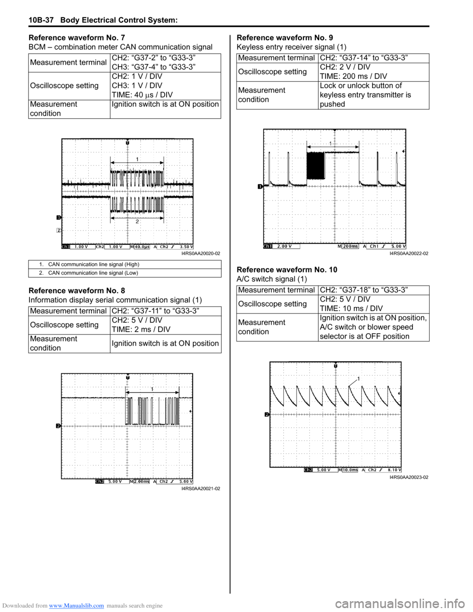
Reference waveform No. 7
BCM – combination meter CAN communication signal
Reference waveform No. 8
Information display serial communication signal (1)Reference waveform No. 9
Keyless entry receiver signal (1)
Reference waveform No. 10
A/C switch signal (1)
Measurement terminal
CH2: “G37-2” to “G33-3”
CH3: “G37-4” to “G33-3”
Oscilloscope setting CH2: 1 V / DIV
CH3: 1 V / DIV
TIME: 40
µs / DIV
Measurement
condition Ignition switch is at ON position
1. CAN communication line signal (High)
2. CAN communication line signal (Low)
Measurement terminal CH2: “G37-11” to “G33-3”
Oscilloscope setting
CH2: 5 V / DIV
TIME: 2 ms / DIV
Measurement
condition Ignition switch is at ON position
I4RS0AA20020-02
I4RS0AA20021-02
Measurement terminal CH2: “G37-14” to “G33-3”
Oscilloscope settingCH2: 2 V / DIV
TIME: 200 ms / DIV
Measurement
condition Lock or unlock button of
keyless entry transmitter is
pushed
Measurement terminal CH2: “G37-18” to “G33-3”
Oscilloscope setting CH2: 5 V / DIV
TIME: 10 ms / DIV
Measurement
condition Ignition switch is at ON position,
A/C switch or blower speed
selector is at OFF position
I4RS0AA20022-02
I4RS0AA20023-02
Page 1446 of 1496
Downloaded from www.Manualslib.com manuals search engine 10C-3 Immobilizer Control System:
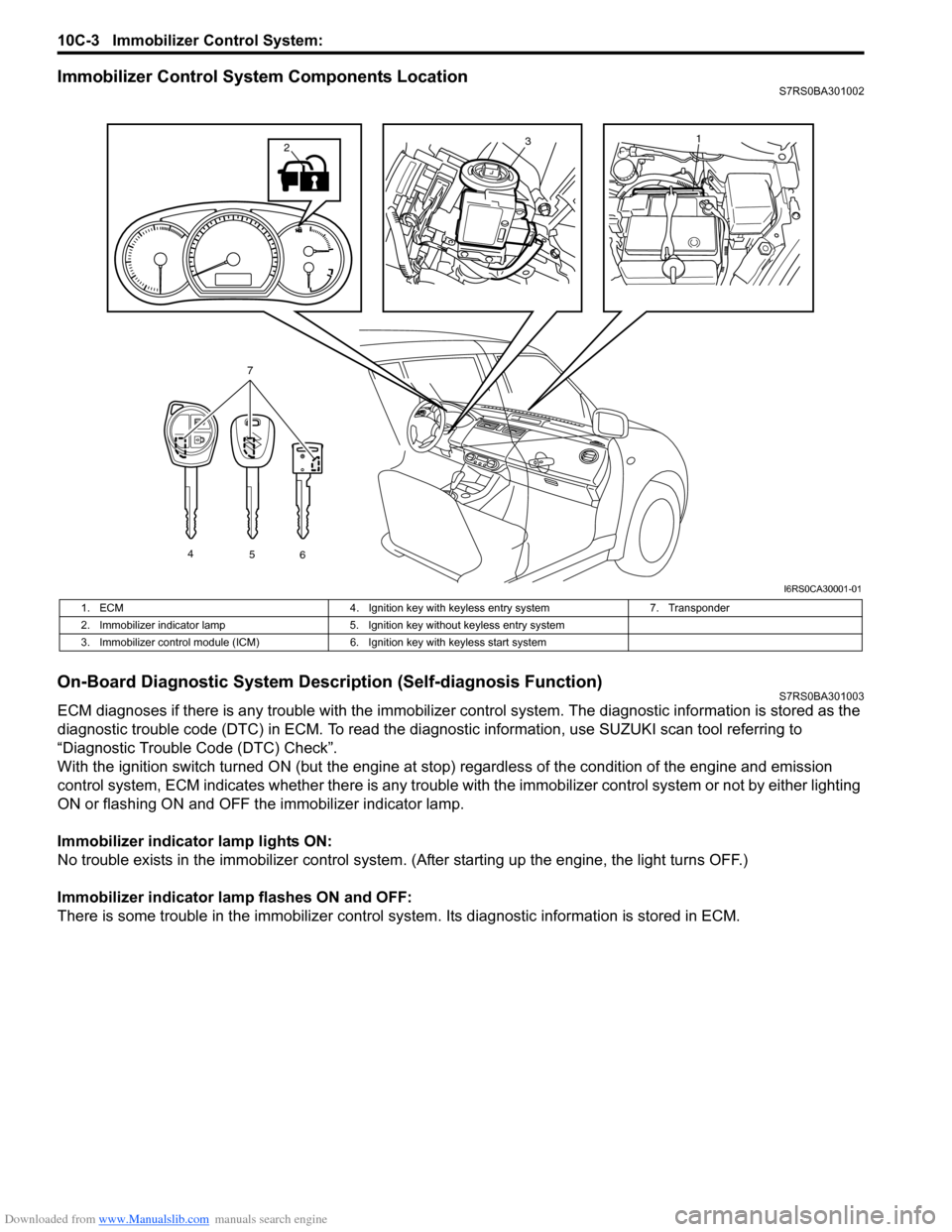
Immobilizer Control System Components LocationS7RS0BA301002
On-Board Diagnostic System Description (Self-diagnosis Function)S7RS0BA301003
ECM diagnoses if there is any trouble with the immobilizer control system. The diagnostic information is stored as the
diagnostic trouble code (DTC) in ECM. To read the di agnostic information, use SUZUKI scan tool referring to
“Diagnostic Trouble Code (DTC) Check”.
With the ignition switch turned ON (but the engine at stop) regardless of the condition of the engine and emission
control system, ECM indicates whether ther e is any trouble with the immobilizer control system or not by either lighting
ON or flashing ON and OFF t he immobilizer indicator lamp.
Immobilizer indicator lamp lights ON:
No trouble exists in the immobilizer control system. (After starting up the engine, the light turns OFF.)
Immobilizer indicator lamp flashes ON and OFF:
There is some trouble in the immo bilizer control system. Its diagnostic information is stored in ECM.
13
4
56
7
2
I6RS0CA30001-01
1. ECM 4. Ignition key with keyless entry system 7. Transponder
2. Immobilizer indicator lamp 5. Ignition key without keyless entry system
3. Immobilizer control module (ICM) 6. Ignition key with keyless start system
Page 1448 of 1496
Downloaded from www.Manualslib.com manuals search engine 10C-5 Immobilizer Control System:
Diagnostic Information and Procedures
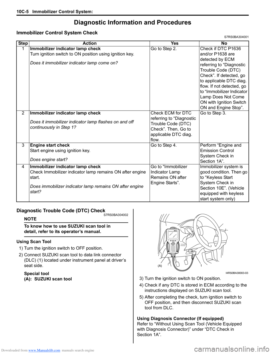
Immobilizer Control System CheckS7RS0BA304001
Diagnostic Trouble Code (DTC) CheckS7RS0BA304002
NOTE
To know how to use SUZUKI scan tool in
detail, refer to its operator’s manual.
Using Scan Tool
1) Turn the ignition switch to OFF position.
2) Connect SUZUKI scan tool to data link connector (DLC) (1) located under instrument panel at driver’s
seat side.
Special tool
(A): SUZUKI scan tool 3) Turn the ignition switch to ON position.
4) Check if any DTC is stored
in ECM according to the
instructions displayed on SUZUKI scan tool.
5) After completing the check, turn ignition switch to
OFF position, and then di sconnect SUZUKI scan
tool from DLC.
Using Diagnosis Connector (If equipped)
Refer to “Without Using Scan Tool (Vehicle Equipped
with Diagnosis Connector)” under “DTC Check in
Section 1A”.
Step Action Yes No
1 Immobilizer indicator lamp check
Turn ignition switch to ON position using ignition key.
Does it immobilizer in dicator lamp come on? Go to Step 2.
Check if DTC P1636
and/or P1638 are
detected by ECM
referring to “Diagnostic
Trouble Code (DTC)
Check”. If detected, go
to applicable DTC diag.
flow. If not detected, go
to “Immobilizer Indicator
Lamp Does Not Come
ON with Ignition Switch
ON and Engine Stop”.
2 Immobilizer indicator lamp check
Does it immobilizer indicato r lamp flashes on and off
continuously in Step 1? Check ECM for DTC
referring to “Diagnostic
Trouble Code (DTC)
Check”. Then, Go to
applicable DTC diag.
flow.Go to Step 3.
3 Engine start check
Start engine using ignition key.
Does engine start? Go to Step 4.
Perform “Engine and
Emission Control
System Check in
Section 1A”.
4 Immobilizer indicator lamp check
Check Immobilizer indicator la mp remains ON after engine
start.
Does immobilizer indicator la mp remains ON after engine
start? Go to “Immobilizer
Indicator Lamp
Remains ON after
Engine Starts”.
Immobilizer system is
good condition. Then go
to “Keyless Start
System Check in
Section 10E”. (Vehicle
equipped with keyless
start system only)
(A)1
I4RS0BA30003-03
Page 1449 of 1496
Downloaded from www.Manualslib.com manuals search engine Immobilizer Control System: 10C-6
Diagnostic Trouble Code (DTC) ClearanceS7RS0BA304003
NOTE
To know how to use SUZUKI scan tool in
detail, refer to its operator’s manual.
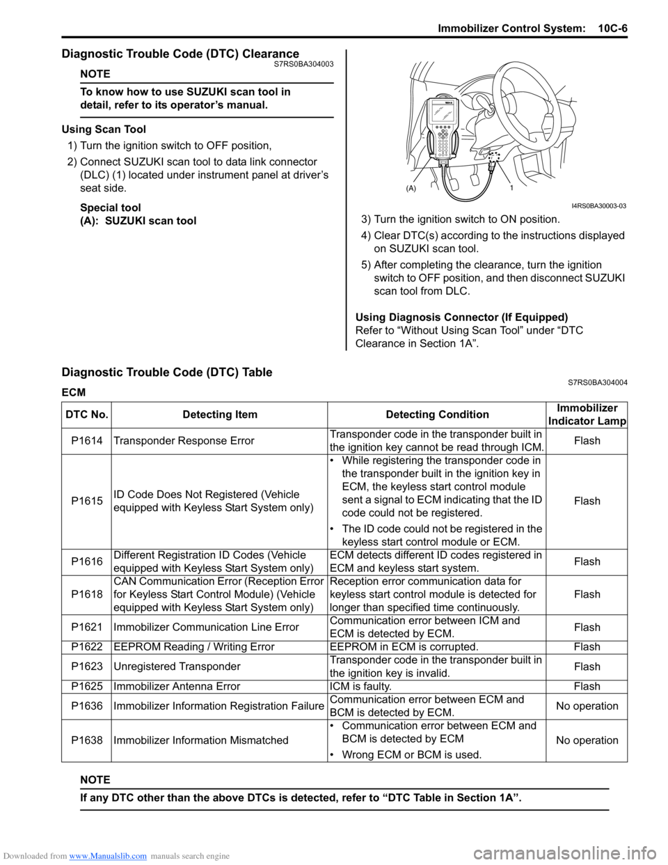
Using Scan Tool
1) Turn the ignition switch to OFF position,
2) Connect SUZUKI scan tool to data link connector (DLC) (1) located under instrument panel at driver’s
seat side.
Special tool
(A): SUZUKI scan tool 3) Turn the ignition switch to ON position.
4) Clear DTC(s) according to the instructions displayed
on SUZUKI scan tool.
5) After completing the clearance, turn the ignition switch to OFF position, and then disconnect SUZUKI
scan tool from DLC.
Using Diagnosis Connector (If Equipped)
Refer to “Without Using Scan Tool” under “DTC
Clearance in Section 1A”.
Diagnostic Trouble Code (DTC) TableS7RS0BA304004
ECM
NOTE
If any DTC other than the above DTCs is detected, refer to “DTC Table in Section 1A”.
(A)1
I4RS0BA30003-03
DTC No. Detecting Item Detecting ConditionImmobilizer
Indicator Lamp
P1614 Transponder Response Error Transponder code in the transponder built in
the ignition key cannot be read through ICM.Flash
P1615 ID Code Does Not Re
gistered (Vehicle
equipped with Keyless Start System only) • While registering the transponder code in
the transponder built in the ignition key in
ECM, the keyless start control module
sent a signal to ECM indicating that the ID
code could not be registered.
• The ID code could not be registered in the keyless start control module or ECM. Flash
P1616 Different Registration ID Codes (Vehicle
equipped with Keyless Start System only) ECM detects different ID codes registered in
ECM and keyless start system.
Flash
P1618 CAN Communication Error (Reception Error
for Keyless Start Control Module) (Vehicle
equipped with Keyless Start System only) Reception error communication data for
keyless start control module is detected for
longer than specified time continuously.
Flash
P1621 Immobilizer Commu nication Line ErrorCommunication error between ICM and
ECM is detected by ECM. Flash
P1622 EEPROM Reading / Writing Error EEPROM in ECM is corrupted.Flash
P1623 Unregistered Transponder Transponder code in the transponder built in
the ignition key is invalid.Flash
P1625 Immobilizer Antenna Error ICM is faulty.Flash
P1636 Immobilizer Information Registration Failure Communication error between ECM and
BCM is detected by ECM.No operation
P1638 Immobilizer Info rmation Mismatched • Communication error between ECM and
BCM is detected by ECM
• Wrong ECM or BCM is used. No operation
Page 1457 of 1496
Downloaded from www.Manualslib.com manuals search engine Immobilizer Control System: 10C-14
DTC P1625: Immobilizer Antenna ErrorS7RS0BA304015
Detecting Condition and Trouble Area
DTC Confirmation Procedure1) Turn ignition switch to ON position.
2) Check DTC in ECM.
Troubleshooting
DTC P1636: Immobilizer Information Registration FailureS7RS0BA304016
DTC Detecting Condition and Trouble Area
Troubleshooting 3
Registration of unregistered ignition key with ECM
1) Register unregistered igniti on key with ECM referring to
“Registration of the Ignition Key”.
Was registration of ignition key completed? Unregistered ignition
key.
Go to Step 4.
4 Registration of the spare ignition key
1) Register the spare ignition key referring to “Registration
of the Ignition Key”.
Was registration of spare ignition key completed? Replace ignition key
which cannot be
registered.
Substitute a known-
good ECM and recheck.
Step Action Yes No
Detecting Condition
Trouble Area
ICM • ICM
•ECM
StepAction YesNo
1 Was “Immobilizer Control S ystem Check” performed? Go to Step 2.Go to “Immobilizer
Control System Check”.
2 DTC confirmation
1) Clear DTC(s) referring to “Diagnostic Trouble Code
(DTC) Clearance”.
2) Turn the ignition switch to OFF position.
3) Check ECM for DTC referring to “Diagnostic Trouble Code (DTC) Check”.
Is DTC P1625 still detected? Replace ICM and
recheck DTC. If DTC
P1625 is still detected,
substitute a known-
good ECM and recheck.
Intermittent trouble.
Check for intermittent
referring to “Intermittent
and Poor Connection
Inspection in Section
00”.
Detecting Condition
Trouble Area
The registration of the immobilizer control system
information in ECM is failed. • CAN communication wire circuits
•BCM
•ECM
Step
Action YesNo
1 Was “Immobilizer Control S ystem Check” performed? Go to Step 2.Go to “Immobilizer
Control System Check”.
2 DTC check of ECM
1) Check ECM for DTC referring to “DTC Check in Section
1A”.
Is DTC P1674, P1675, P1678 and/or P1685 detected? Go to applicable DTC
diag. flow.
Go to Step 3.