Fuel pressure sensor SUZUKI SWIFT 2006 2.G Service Owner's Guide
[x] Cancel search | Manufacturer: SUZUKI, Model Year: 2006, Model line: SWIFT, Model: SUZUKI SWIFT 2006 2.GPages: 1496, PDF Size: 34.44 MB
Page 227 of 1496
Downloaded from www.Manualslib.com manuals search engine Engine General Information and Diagnosis: 1A-177
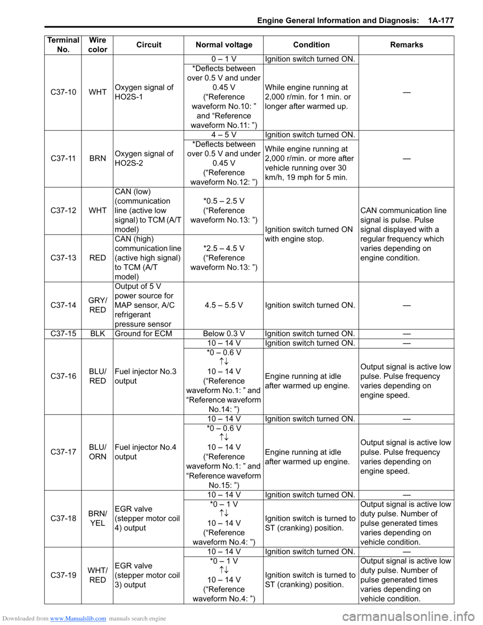
C37-10 WHTOxygen signal of
HO2S-1 0 – 1 V Ignition switch turned ON.
—
*Deflects between
over 0.5 V and under 0.45 V
(“Reference
waveform No.10: ” and “Reference
waveform No.11: ”) While engine running at
2,000 r/min. for 1 min. or
longer after warmed up.
C37-11 BRN Oxygen signal of
HO2S-2 4 – 5 V Ignition switch turned ON.
—
*Deflects between
over 0.5 V and under 0.45 V
(“Reference
waveform No.12: ”) While engine running at
2,000 r/min. or more after
vehicle running over 30
km/h, 19 mph for 5 min.
C37-12 WHT CAN (low)
(communication
line (active low
signal) to TCM (A/T
model) *0.5 – 2.5 V
(“Reference
waveform No.13: ”) Ignition switch turned ON
with engine stop. CAN communication line
signal is pulse. Pulse
signal displayed with a
regular frequency which
varies depending on
engine condition.
C37-13 RED CAN (high)
communication line
(active high signal)
to TCM (A/T
model) *2.5 – 4.5 V
(“Reference
waveform No.13: ”)
C37-14 GRY/
RED Output of 5 V
power source for
MAP sensor, A/C
refrigerant
pressure sensor
4.5 – 5.5 V Ignition switch turned ON. —
C37-15 BLK Ground for ECM Below 0.3 V Ignition switch turned ON. —
C37-16 BLU/
RED Fuel injector No.3
output 10 – 14 V Ignition switch turned ON. —
*0 – 0.6 V ↑↓
10 – 14 V
(“Reference
waveform No.1: ” and
“Reference waveform No.14: ”) Engine running at idle
after warmed up engine.
Output signal is active low
pulse. Pulse frequency
varies depending on
engine speed.
C37-17 BLU/
ORNFuel injector No.4
output 10 – 14 V Ignition switch turned ON. —
*0 – 0.6 V ↑↓
10 – 14 V
(“Reference
waveform No.1: ” and
“Reference waveform No.15: ”) Engine running at idle
after warmed up engine.
Output signal is active low
pulse. Pulse frequency
varies depending on
engine speed.
C37-18 BRN/
YEL EGR valve
(stepper motor coil
4) output 10 – 14 V Ignition switch turned ON. —
*0 – 1 V ↑↓
10 – 14 V
(“Reference
waveform No.4: ”) Ignition switch is turned to
ST (cranking) position. Output signal is active low
duty pulse. Number of
pulse generated times
varies depending on
vehicle condition.
C37-19 WHT/
RED EGR valve
(stepper motor coil
3) output 10 – 14 V Ignition switch turned ON. —
*0 – 1 V ↑↓
1
0 – 14 V
(“Reference
waveform No.4: ”) Ignition switch is turned to
ST (cranking) position. Output signal is active low
duty pulse. Number of
pulse generated times
varies depending on
vehicle condition.
Terminal
No. Wire
color Circuit Normal voltage
ConditionRemarks
Page 234 of 1496
Downloaded from www.Manualslib.com manuals search engine 1A-184 Engine General Information and Diagnosis:
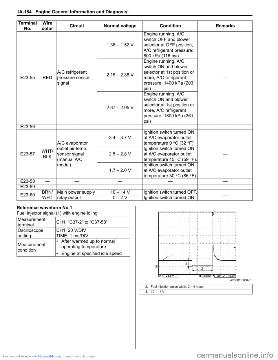
Reference waveform No.1
Fuel injector signal (1) with engine idling
E23-55 RED
A/C refrigerant
pressure sensor
signal 1.38 – 1.52 V
Engine running, A/C
switch OFF and blower
selector at OFF position,
A/C refrigerant pressure:
800 kPa (116 psi)
—
2.15 – 2.38 V Engine running, A/C
switch ON and blower
selector at 1st position or
more, A/C refrigerant
pressure: 1400 kPa (203
psi)
2.67 – 2.95 V Engine running, A/C
switch ON and blower
selector at 1st position or
more, A/C refrigerant
pressure: 1800 kPa (261
psi)
E23-56 — — — — —
E23-57 WHT/
BLK A/C evaporator
outlet air temp.
sensor signal
(manual A/C
model) 3.4 – 3.7 V
Ignition switch turned ON
at A/C evaporator outlet
temperature 0
°C (32 °F).
—
2.5 – 2.8 V Ignition switch turned ON
at A/C evaporator outlet
temperature 15
°C (59 °F).
1.7 – 2.0 V Ignition switch turned ON
at A/C evaporator outlet
temperature 30
°C (86 °F).
E23-58 — — — — —
E23-59 — — — — —
E23-60 BRN/
WHT Main power supply
relay output 10 – 14 V Ignition switch turned OFF.
—
0 – 2 V Ignition switch turned ON.
Terminal
No. Wire
color Circuit Normal voltage Condition Remarks
Measurement
terminal CH1: “C37-2” to “C37-58”
Oscilloscope
setting CH1: 20 V/DIV
TIME: 1 ms/DIV
Measurement
condition • After warmed up to normal
operating temperature
• Engine at specified idle speed
2. Fuel injection pulse width: 2 – 4 msec.
3. 10 – 14 V
I4RS0B110050-01
Page 244 of 1496
Downloaded from www.Manualslib.com manuals search engine 1A-194 Engine General Information and Diagnosis:
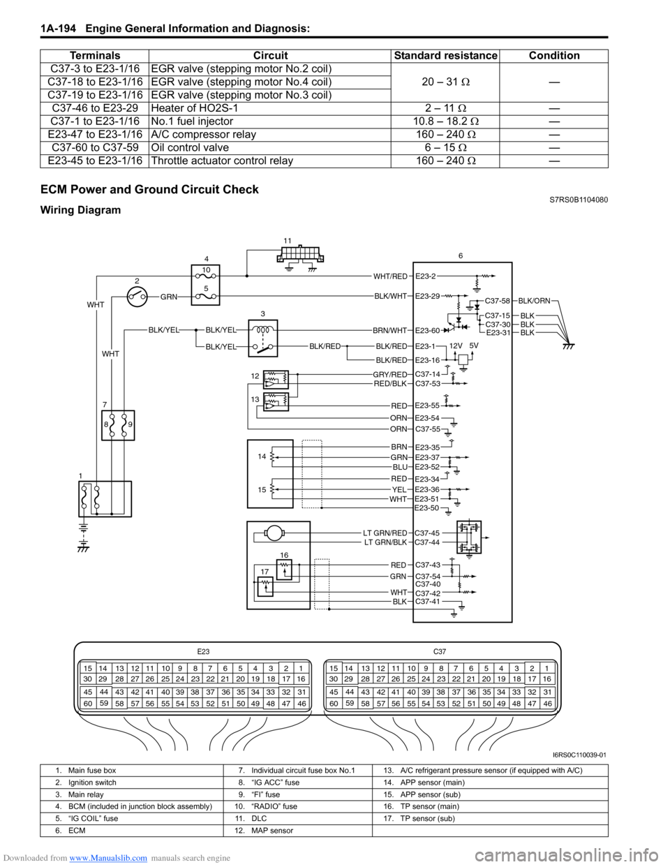
ECM Power and Ground Circuit CheckS7RS0B1104080
Wiring DiagramC37-3 to E23-1/16 EGR valve
(stepping motor No.2 coil)
20 – 31 Ω —
C37-18 to E23-1/16 EGR valv e (stepping motor No.4 coil)
C37-19 to E23-1/16 EGR valv e (stepping motor No.3 coil)
C37-46 to E23-29 Heater of HO2S-1 2 – 11 Ω—
C37-1 to E23-1/16 No.1 fuel injector 10.8 – 18.2 Ω —
E23-47 to E23-1/16 A/C compressor relay 160 – 240 Ω —
C37-60 to C37-59 Oil control valve 6 – 15 Ω —
E23-45 to E23-1/16 Throttle actuator control relay 160 – 240 Ω —
Terminals
CircuitStandard resistance Condition
E23 C37
34
1819
567
1011
17
20
47 46
495051
2122
52 16
25 9
24
14
29
55
57 54 53
59
60 58 2
262728
15
30
56 4832 31
34353637
40
42 39 38
44
45 43 41 331
1213
238
34
1819
567
1011
17
20
47 46
495051
2122
52 16
25 9
24
14
29
55
57 54 53
59
60 58 2
262728
15
30
56 4832 31
34353637
40
42 39 38
44
45 43 41 331
1213
238
BLK/RED
BLK/REDBLK/RED
BLK/YELBLK/YEL
BLK/YEL
GRN
BRN/WHT
12V
5VE23-1
E23-60
E23-16
WHT 2
4
11
6
3
12
13 14
7
1
16
17
89
15
10
5
WHT/REDE23-2
C37-58
C37-15C37-30
BLK/ORN
BLKBLKE23-31BLK
WHT
GRY/REDRED/BLK
ORN
C37-14C37-53
C37-55E23-54
REDE23-55
GRNBRN
BLU
REDYELWHT
E23-35E23-37E23-52
E23-51
E23-34E23-36
E23-50
LT GRN/REDLT GRN/BLKC37-45C37-44
C37-43
C37-54C37-40C37-42C37-41
RED
GRN
WHTBLK
ORN
BLK/WHTE23-29
I6RS0C110039-01
1. Main fuse box 7. Individual circuit fuse box No.1 13. A/C refrigerant pressure sensor (if equipped with A/C)
2. Ignition switch 8. “IG ACC” fuse14. APP sensor (main)
3. Main relay 9. “FI” fuse15. APP sensor (sub)
4. BCM (included in junction block assembly) 10. “RADIO” fuse 16. TP sensor (main)
5. “IG COIL” fuse 11. DLC17. TP sensor (sub)
6. ECM 12. MAP sensor
Page 247 of 1496
Downloaded from www.Manualslib.com manuals search engine Engine General Information and Diagnosis: 1A-197
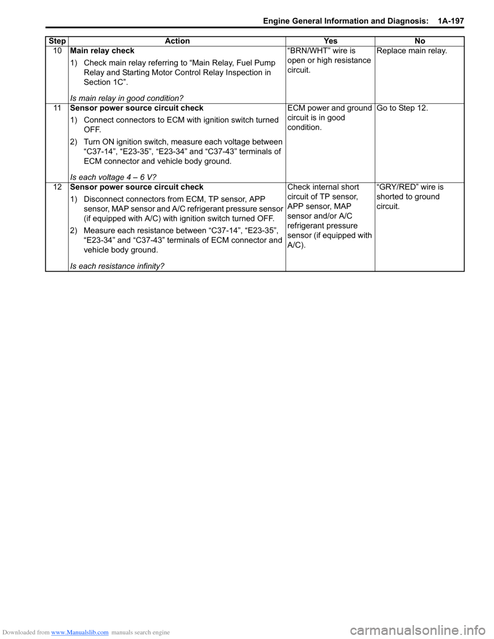
10Main relay check
1) Check main relay referring to “Main Relay, Fuel Pump
Relay and Starting Motor Control Relay Inspection in
Section 1C”.
Is main relay in good condition? “BRN/WHT” wire is
open or high resistance
circuit.
Replace main relay.
11 Sensor power source circuit check
1) Connect connectors to ECM with ignition switch turned
OFF.
2) Turn ON ignition switch, measure each voltage between “C37-14”, “E23-35”, “E23-34” and “C37-43” terminals of
ECM connector and vehicle body ground.
Is each voltage 4 – 6 V? ECM power and ground
circuit is in good
condition.
Go to Step 12.
12 Sensor power source circuit check
1) Disconnect connectors from ECM, TP sensor, APP
sensor, MAP sensor and A/C refrigerant pressure sensor
(if equipped with A/C) with i gnition switch turned OFF.
2) Measure each resistance between “C37-14”, “E23-35”, “E23-34” and “C37-43” terminals of ECM connector and
vehicle body ground.
Is each resistance infinity? Check internal short
circuit of TP sensor,
APP sensor, MAP
sensor and/or A/C
refrigerant pressure
sensor (if equipped with
A/C).
“GRY/RED” wire is
shorted to ground
circuit.
Step Action Yes No
Page 302 of 1496

Downloaded from www.Manualslib.com manuals search engine 1D-17 Engine Mechanical:
Engine Assembly Removal and InstallationS7RS0B1406011
NOTE
After replacing electric throttle body
assembly, perform calibration of throttle
valve referring to “Electric Throttle Body
System Calibration in Section 1C”.
Removal1) Relieve fuel pressure according to “Fuel Pressure Relief Procedure in Section 1G”.
2) Disconnect negative and pos itive cable at battery.
3) Remove battery and tray.
4) Remove engine hood after disconnecting windshield washer hose.
5) Remove right and left side engine under covers.
6) Remove A/C compressor belt by referring to “Compressor Drive Belt Remo val and Installation in
Section 7B” or “Compressor Drive Belt Removal and
Installation in Section 7B”.
7) Drain engine oil, transaxle oil and coolant.
8) Remove cowl top plate referring to “Cowl Top Components in Section 9K”.
9) Remove air cleaner assembly referring to “Air Cleaner Components”.
10) With hose connected, detach A/C compressor from its bracket (A/C model) referring to “Compressor
Assembly Removal and Installation in Section 7B” or
“Compressor Assembly Removal and Installation in
Section 7B”.
CAUTION!
Suspend removed A/C compressor at a place
where no damage will be caused during
removal and installation of engine assembly.
11) Remove intake manifold rear stiffener (1) from intake manifold and cylinder block. 12) Disconnect the following electric wires:
• MAP sensor (1)
• ECT sensor (2)
•EGR valve (3)
• CMP sensor (4)
• Electric throttle body assembly (5)
• Ignition coil assembly (6)
• Injectors (7)
• Heated oxygen sensor No. 2 (8) and No. 1 (9)
• Oil control valve (10)
• Engine oil pressure switch (11)
• CKP sensor (12)
• Knock sensor (13)
• Back up light switch (14)
• Generator (15)
• Starting motor (16)
• Ground terminal (17) from intake manifold
• Battery ground terminal (18) from exhaust manifold
• Battery ground cable (19) from transaxle
• Magnet clutch switch of A/C compressor (A/C model)
• Each wire harness clamps
• Output shaft speed sensor (VSS) (34) (A/T model)
• Solenoid valve (33) (A/T model)
• Transmission range sensor (32) (A/T model)
• Input shaft speed sensor (31) (A/T model)
13) Remove fuse box from its bracket.
14) Disconnect the following cables: • Gear select control cable (23) (M/T model)
• Gear shift control cable (24) (M/T model)
• A/T select cable (A/T model)
15) Disconnect the following hoses: • Brake booster hose (26) from intake manifold
• Radiator inlet and outlet hoses (20) from each pipe
• Heater inlet and outlet hoses (21) from each pipe
• Fuel feed hoses (22) from fuel feed pipe
• EVAP canister purge valve hose (30) from purge pipe
• A/T fluid cooler hoses (A/T model)
16) With hose connected, detach clutch operating cylinder (25). (M/T model)
CAUTION!
Suspend removed clutch operating cylinder
at a place where no damage will be caused
during removal and installation of engine
assembly.
1
I6RS0B141014-01
Page 377 of 1496
Downloaded from www.Manualslib.com manuals search engine Fuel System: 1G-2
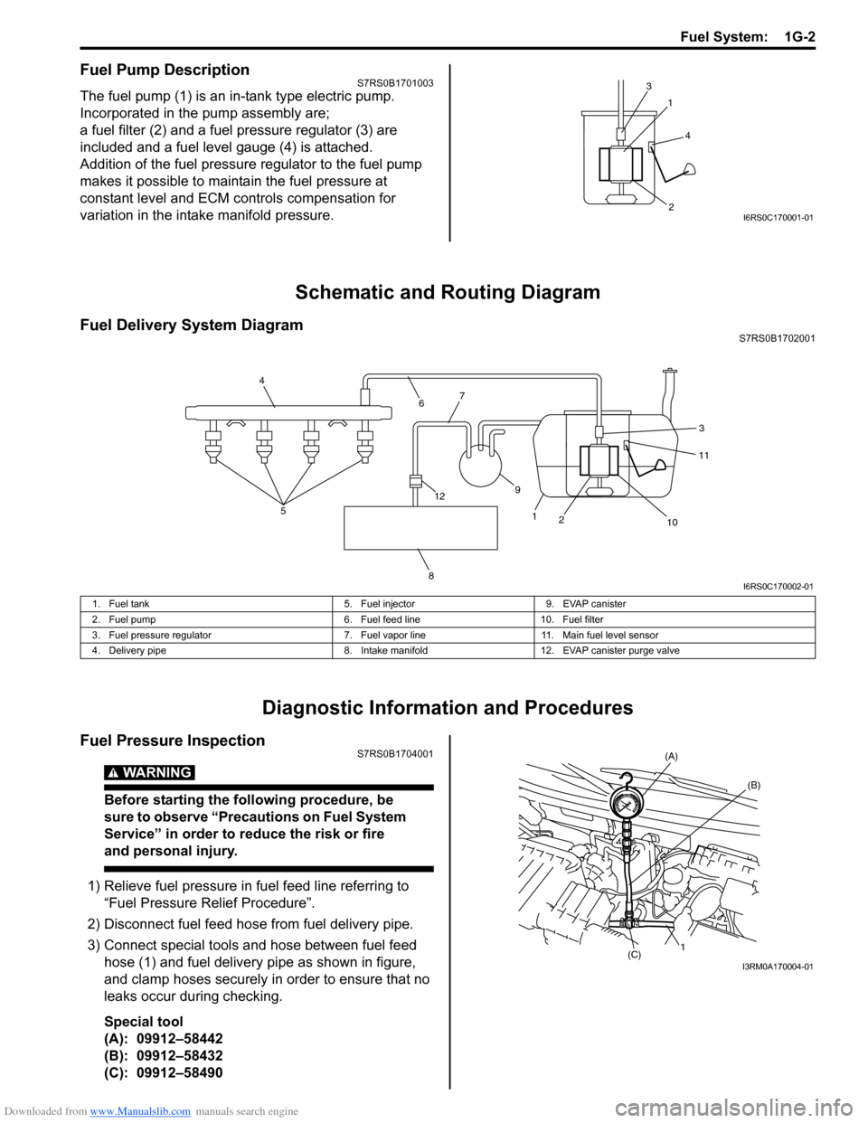
Fuel Pump DescriptionS7RS0B1701003
The fuel pump (1) is an in-tank type electric pump.
Incorporated in the pump assembly are;
a fuel filter (2) and a fuel pressure regulator (3) are
included and a fuel level gauge (4) is attached.
Addition of the fuel pressure regulator to the fuel pump
makes it possible to mainta in the fuel pressure at
constant level and ECM controls compensation for
variation in the intake manifold pressure.
Schematic and Routing Diagram
Fuel Delivery System DiagramS7RS0B1702001
Diagnostic Information and Procedures
Fuel Pressure InspectionS7RS0B1704001
WARNING!
Before starting the following procedure, be
sure to observe “Precautions on Fuel System
Service” in order to reduce the risk or fire
and personal injury.
1) Relieve fuel pressure in fuel feed line referring to
“Fuel Pressure Relief Procedure”.
2) Disconnect fuel feed hose from fuel delivery pipe.
3) Connect special tools and hose between fuel feed hose (1) and fuel delivery pipe as shown in figure,
and clamp hoses securely in order to ensure that no
leaks occur during checking.
Special tool
(A): 09912–58442
(B): 09912–58432
(C): 09912–58490
1
3
2
4
I6RS0C170001-01
4
6 7
8
12
2 3
11
10
5
1
9
I6RS0C170002-01
1. Fuel tank
5. Fuel injector9. EVAP canister
2. Fuel pump 6. Fuel feed line10. Fuel filter
3. Fuel pressure regulator 7. Fuel vapor line 11. Main fuel level sensor
4. Delivery pipe 8. Intake manifold12. EVAP canister purge valve
1
(C) (B)
(A)
I3RM0A170004-01
Page 383 of 1496
Downloaded from www.Manualslib.com manuals search engine Fuel System: 1G-8
Installation1) Install clamps to marked location on pipes. If clamp is deformed, its claw is bent or broken, replace it with
new one.
2) Install pipes with pipe clamps to vehicle.
3) Connect fuel hoses and pipes to each pipe referring to “Fuel Hose Disconnecting and Reconnecting”.
4) Connect negative cable at battery.
5) With engine OFF, turn igniti on switch to ON position
and check for fuel leaks.
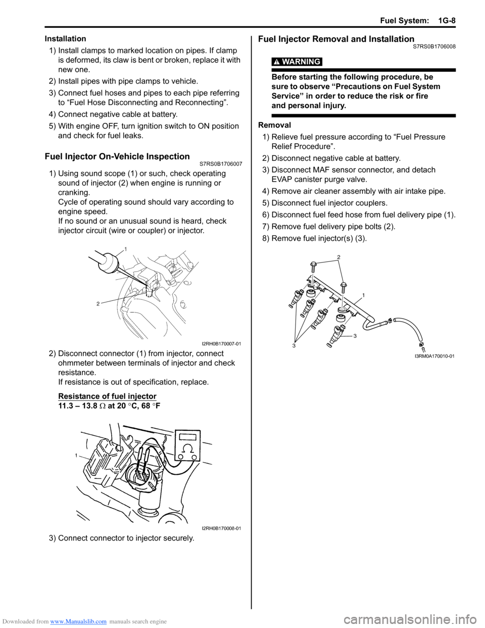
Fuel Injector On-Vehicle InspectionS7RS0B1706007
1) Using sound scope (1) or such, check operating sound of injector (2) when engine is running or
cranking.
Cycle of operating sound should vary according to
engine speed.
If no sound or an unusual sound is heard, check
injector circuit (wire or coupler) or injector.
2) Disconnect connector (1) from injector, connect ohmmeter between terminals of injector and check
resistance.
If resistance is out of specification, replace.
Resistance of fuel injector
11.3 – 13.8 Ω at 20 °C, 68 °F
3) Connect connector to injector securely.
Fuel Injector Removal and InstallationS7RS0B1706008
WARNING!
Before starting the following procedure, be
sure to observe “Precautions on Fuel System
Service” in order to reduce the risk or fire
and personal injury.
Removal 1) Relieve fuel pressure according to “Fuel Pressure Relief Procedure”.
2) Disconnect negative cable at battery.
3) Disconnect MAF sensor connector, and detach EVAP canister purge valve.
4) Remove air cleaner assembly with air intake pipe.
5) Disconnect fuel injector couplers.
6) Disconnect fuel feed hose from fuel delivery pipe (1).
7) Remove fuel delivery pipe bolts (2).
8) Remove fuel injector(s) (3).
I2RH0B170007-01
I2RH0B170008-01
2
1
3
3
I3RM0A170010-01
Page 391 of 1496
Downloaded from www.Manualslib.com manuals search engine Fuel System: 1G-16
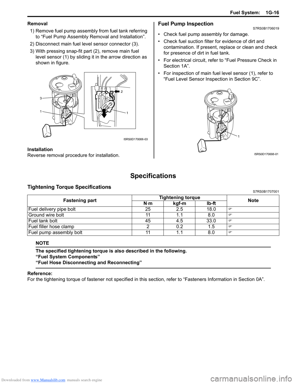
Removal1) Remove fuel pump assembly from fuel tank referring to “Fuel Pump Assembly Removal and Installation”.
2) Disconnect main fuel level sensor connector (3).
3) With pressing snap-fit part (2), remove main fuel level sensor (1) by sliding it in the arrow direction as
shown in figure.
Installation
Reverse removal procedure for installation.Fuel Pump InspectionS7RS0B1706019
• Check fuel pump assembly for damage.
• Check fuel suction filter for evidence of dirt and contamination. If present, replace or clean and check
for presence of dirt in fuel tank.
• For electrical circuit, refer to “Fuel Pressure Check in Section 1A”.
• For inspection of main fuel level sensor (1), refer to “Fuel Level Sensor Inspection in Section 9C”.
Specifications
Tightening Torque SpecificationsS7RS0B1707001
NOTE
The specified tightening torque is also described in the following.
“Fuel System Components”
“Fuel Hose Disconnecting and Reconnecting”
Reference:
For the tightening torque of fastener not specified in this section, refer to “Fasteners Information in Section 0A”.
1
21
3
I5RS0D170006-031
I5RS0D170008-01
Fastening part
Tightening torque
Note
N ⋅mkgf-mlb-ft
Fuel delivery pipe bolt 25 2.5 18.0 �)
Ground wire bolt 11 1.1 8.0 �)
Fuel tank bolt 45 4.5 33.0 �)
Fuel filler hose clamp 2 0.2 1.5 �)
Fuel pump assembly bolt 11 1.1 8.0 �)
Page 669 of 1496
Downloaded from www.Manualslib.com manuals search engine Automatic Transmission/Transaxle: 5A-25
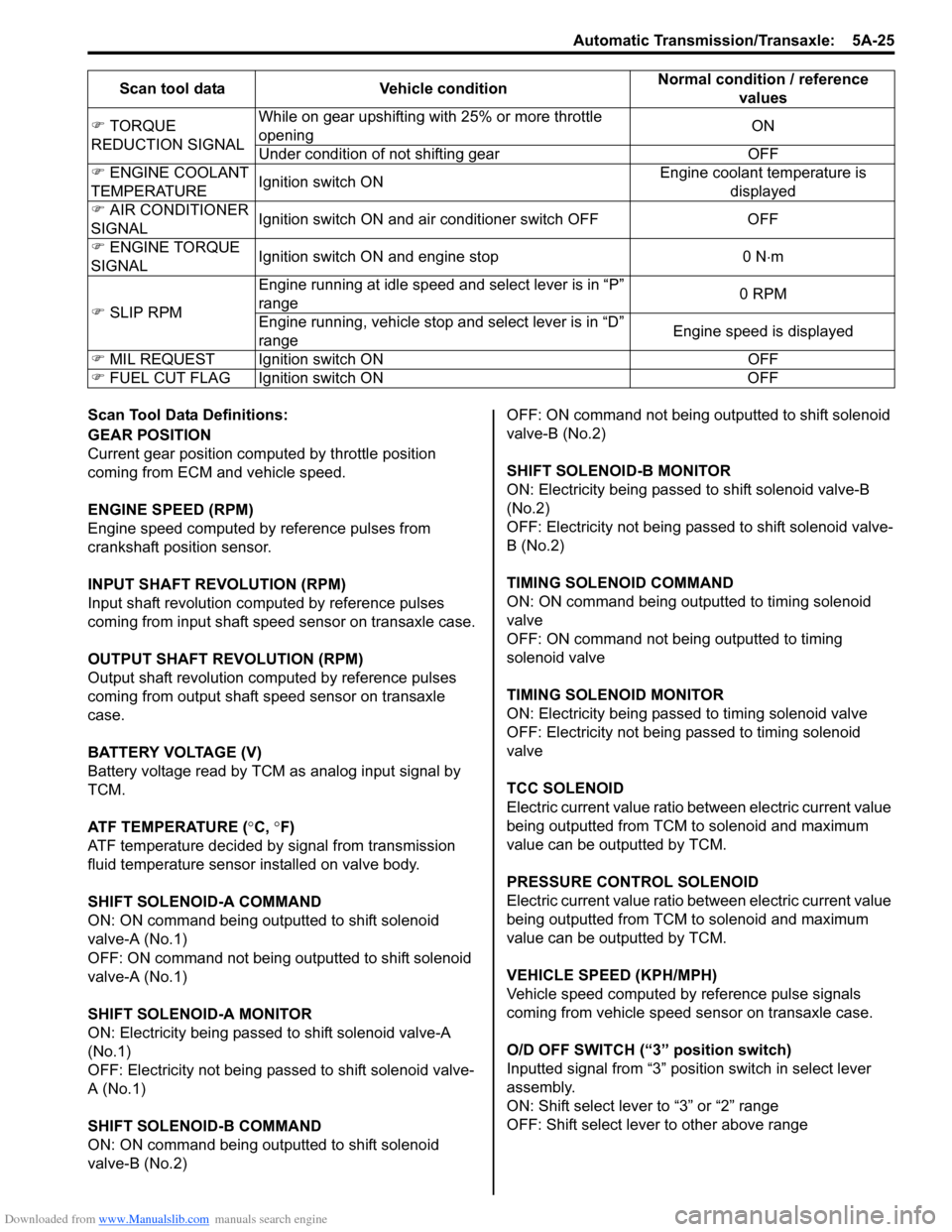
Scan Tool Data Definitions:
GEAR POSITION
Current gear position computed by throttle position
coming from ECM and vehicle speed.
ENGINE SPEED (RPM)
Engine speed computed by reference pulses from
crankshaft position sensor.
INPUT SHAFT REVOLUTION (RPM)
Input shaft revolution computed by reference pulses
coming from input shaft speed sensor on transaxle case.
OUTPUT SHAFT REVOLUTION (RPM)
Output shaft revolution computed by reference pulses
coming from output shaft speed sensor on transaxle
case.
BATTERY VOLTAGE (V)
Battery voltage read by TCM as analog input signal by
TCM.
ATF TEMPERATURE (°C, °F)
ATF temperature decided by signal from transmission
fluid temperature sensor installed on valve body.
SHIFT SOLENOID-A COMMAND
ON: ON command being outputted to shift solenoid
valve-A (No.1)
OFF: ON command not being outputted to shift solenoid
valve-A (No.1)
SHIFT SOLENOID-A MONITOR
ON: Electricity being passed to shift solenoid valve-A
(No.1)
OFF: Electricity not being passed to shift solenoid valve-
A (No.1)
SHIFT SOLENOID-B COMMAND
ON: ON command being outputted to shift solenoid
valve-B (No.2) OFF: ON command not being outputted to shift solenoid
valve-B (No.2)
SHIFT SOLENOID-B MONITOR
ON: Electricity being passed to shift solenoid valve-B
(No.2)
OFF: Electricity not being passed to shift solenoid valve-
B (No.2)
TIMING SOLENOID COMMAND
ON: ON command being outputted to timing solenoid
valve
OFF: ON command not being outputted to timing
solenoid valve
TIMING SOLENOID MONITOR
ON: Electricity being passed to timing solenoid valve
OFF: Electricity not being passed to timing solenoid
valve
TCC SOLENOID
Electric current value ratio between electric current value
being outputted from TCM to solenoid and maximum
value can be outputted by TCM.
PRESSURE CONTROL SOLENOID
Electric current value ratio between electric current value
being outputted from TCM to solenoid and maximum
value can be outputted by TCM.
VEHICLE SPEED (KPH/MPH)
Vehicle speed computed by reference pulse signals
coming from vehicle speed sensor on transaxle case.
O/D OFF SWITCH (“3” position switch)
Inputted signal from “3” position switch in select lever
assembly.
ON: Shift select lever to “3” or “2” range
OFF: Shift select lever to other above range
�)
TORQUE
REDUCTION SIGNAL While on gear upshifting with 25% or more throttle
opening
ON
Under condition of not shifting gear OFF
�) ENGINE COOLANT
TEMPERATURE Ignition switch ON Engine coolant temperature is
displayed
�) AIR CONDITIONER
SIGNAL Ignition switch ON and air conditioner switch OFF OFF
�) ENGINE TORQUE
SIGNAL Ignition switch ON and engine stop 0 N
⋅m
�) SLIP RPM Engine running at idle speed
and select lever is in “P”
range 0 RPM
Engine running, vehicle stop and select lever is in “D”
range Engine speed is displayed
�) MIL REQUEST Ignition switch ON OFF
�) FUEL CUT FLAG Ignition switch ON OFFScan tool data Vehicle condition
Normal condition / reference
values
Page 670 of 1496
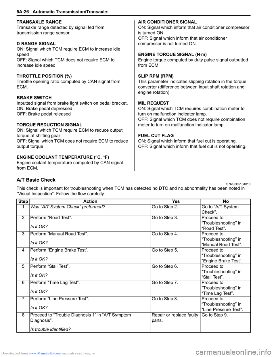
Downloaded from www.Manualslib.com manuals search engine 5A-26 Automatic Transmission/Transaxle:
TRANSAXLE RANGE
Transaxle range detected by signal fed from
transmission range sensor.
D RANGE SIGNAL
ON: Signal which TCM require ECM to increase idle
speed
OFF: Signal which TCM does not require ECM to
increase idle speed
THROTTLE POSITION (%)
Throttle opening ratio computed by CAN signal from
ECM.
BRAKE SWITCH
Inputted signal from brake light switch on pedal bracket.
ON: Brake pedal depressed
OFF: Brake pedal released
TORQUE REDUCTION SIGNAL
ON: Signal which TCM require ECM to reduce output
torque at shifting gear
OFF: Signal which TCM does not require ECM to reduce
output torque
ENGINE COOLANT TEMPERATURE ( °C, °F)
Engine coolant temperature computed by CAN signal
from ECM. AIR CONDITIONER SIGNAL
ON: Signal which inform that air conditioner compressor
is turned ON.
OFF: Signal which inform that air conditioner
compressor is not turned ON.
ENGINE TORQUE SIGNAL (N
⋅m)
Engine torque computed by duty pulse signal outputted
from ECM.
SLIP RPM (RPM)
This parameter indicates slip ping rotation in the torque
converter (difference between input shaft rotation and
engine rotation)
MIL REQUEST
ON: Signal which TCM requires combination meter to
turn on malfunction indicator lamp.
OFF: Signal which TCM does not require combination
meter to turn on malf unction indicator lamp.
FUEL CUT FLAG
ON: Signal which inform that fuel cut is operating.
OFF: Signal which inform that fuel cut is not operating.
A/T Basic CheckS7RS0B5104010
This check is important for troubleshooting when TCM has detected no DTC and no abnormality has been noted in
“Visual Inspection”. Fo llow the flow carefully.
Step Action YesNo
1 Was “A/T System Check” preformed? Go to Step 2.Go to “A/T System
Check”.
2 Perform “Road Test”.
Is it OK? Go to Step 3.
Proceed to
“Troubleshooting” in
“Road Test”.
3 Perform “Manual Road Test”.
Is it OK? Go to Step 4.
Proceed to
“Troubleshooting” in
“Manual Road Test”.
4 Perform “Engine Brake Test”.
Is it OK? Go to Step 5.
Proceed to
“Troubleshooting” in
“Engine Brake Test”.
5 Perform “Stall Test”.
Is it OK? Go to Step 6.
Proceed to
“Troubleshooting” in
“Stall Test”.
6 Perform “Time Lag Test”.
Is it OK? Go to Step 7.
Proceed to
“Troubleshooting” in
“Time Lag Test”.
7 Perform “Line Pressure Test”.
Is it OK? Go to Step 8.
Proceed to
“Troubleshooting” in
“Line Pressure Test”.
8 Proceed to “Trouble Diag nosis 1” in “A/T Symptom
Diagnosis”.
Is trouble identified? Repair or replace faulty
parts.
Go to Step 9.