air control valve SUZUKI SWIFT 2006 2.G Service Owner's Guide
[x] Cancel search | Manufacturer: SUZUKI, Model Year: 2006, Model line: SWIFT, Model: SUZUKI SWIFT 2006 2.GPages: 1496, PDF Size: 34.44 MB
Page 142 of 1496
Downloaded from www.Manualslib.com manuals search engine 1A-92 Engine General Information and Diagnosis:
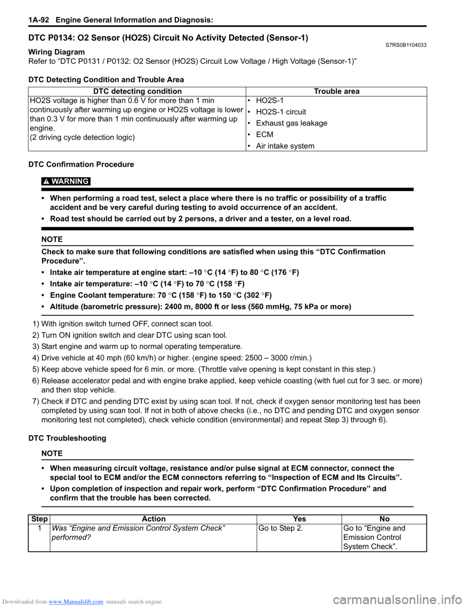
DTC P0134: O2 Sensor (HO2S) Circuit No Activity Detected (Sensor-1)S7RS0B1104033
Wiring Diagram
Refer to “DTC P0131 / P0132: O2 Sensor (HO2S) Circuit Low Voltage / High Voltage (Sensor-1)”
DTC Detecting Condition and Trouble Area
DTC Confirmation Procedure
WARNING!
• When performing a road test, select a place where there is no traffic or possibility of a traffic accident and be very careful during testing to avoid occurrence of an accident.
• Road test should be carried out by 2 persons, a driver and a tester, on a level road.
NOTE
Check to make sure that following conditions ar e satisfied when using this “DTC Confirmation
Procedure”.
• Intake air temperature at engine start: –10 °C (14 ° F) to 80 °C (176 °F)
• Intake air temperature: –10 °C (14 °F) to 70 °C (158 °F)
• Engine Coolant temperature: 70 °C (158 °F) to 150 °C (302 ° F)
• Altitude (barometric pressure): 2400 m, 8000 ft or less (560 mmHg, 75 kPa or more)
1) With ignition switch turned OFF, connect scan tool.
2) Turn ON ignition switch and clear DTC using scan tool.
3) Start engine and warm up to normal operating temperature.
4) Drive vehicle at 40 mph (60 km/h) or higher. (engine speed: 2500 – 3000 r/min.)
5) Keep above vehicle speed for 6 min. or more. (Throt tle valve opening is kept constant in this step.)
6) Release accelerator pedal and with engine brake applied, keep vehicle coasting (with fuel cut for 3 sec. or more)
and then stop vehicle.
7) Check if DTC and pending DTC exist by using scan tool. If not, check if oxygen sensor monitoring test has been
completed by using scan tool. If not in both of above c hecks (i.e., no DTC and pending DTC and oxygen sensor
monitoring test not completed), check vehicle cond ition (environmental) and repeat Step 3) through 6).
DTC Troubleshooting
NOTE
• When measuring circuit voltage, resistance and/ or pulse signal at ECM connector, connect the
special tool to ECM and/or the ECM connectors re ferring to “Inspection of ECM and Its Circuits”.
• Upon completion of inspection and repair work, perform “DTC Confirmation Procedure” and confirm that the trouble has been corrected.
DTC detecting condition Trouble area
HO2S voltage is higher than 0.6 V for more than 1 min
continuously after warming up engine or HO2S voltage is lower
than 0.3 V for more than 1 min continuously after warming up
engine.
(2 driving cycle detection logic) •HO2S-1
• HO2S-1 circuit
• Exhaust gas leakage
•ECM
• Air intake system
Step
Action YesNo
1 Was “Engine and Emission Control System Check”
performed? Go to Step 2.
Go to “Engine and
Emission Control
System Check”.
Page 145 of 1496
Downloaded from www.Manualslib.com manuals search engine Engine General Information and Diagnosis: 1A-95
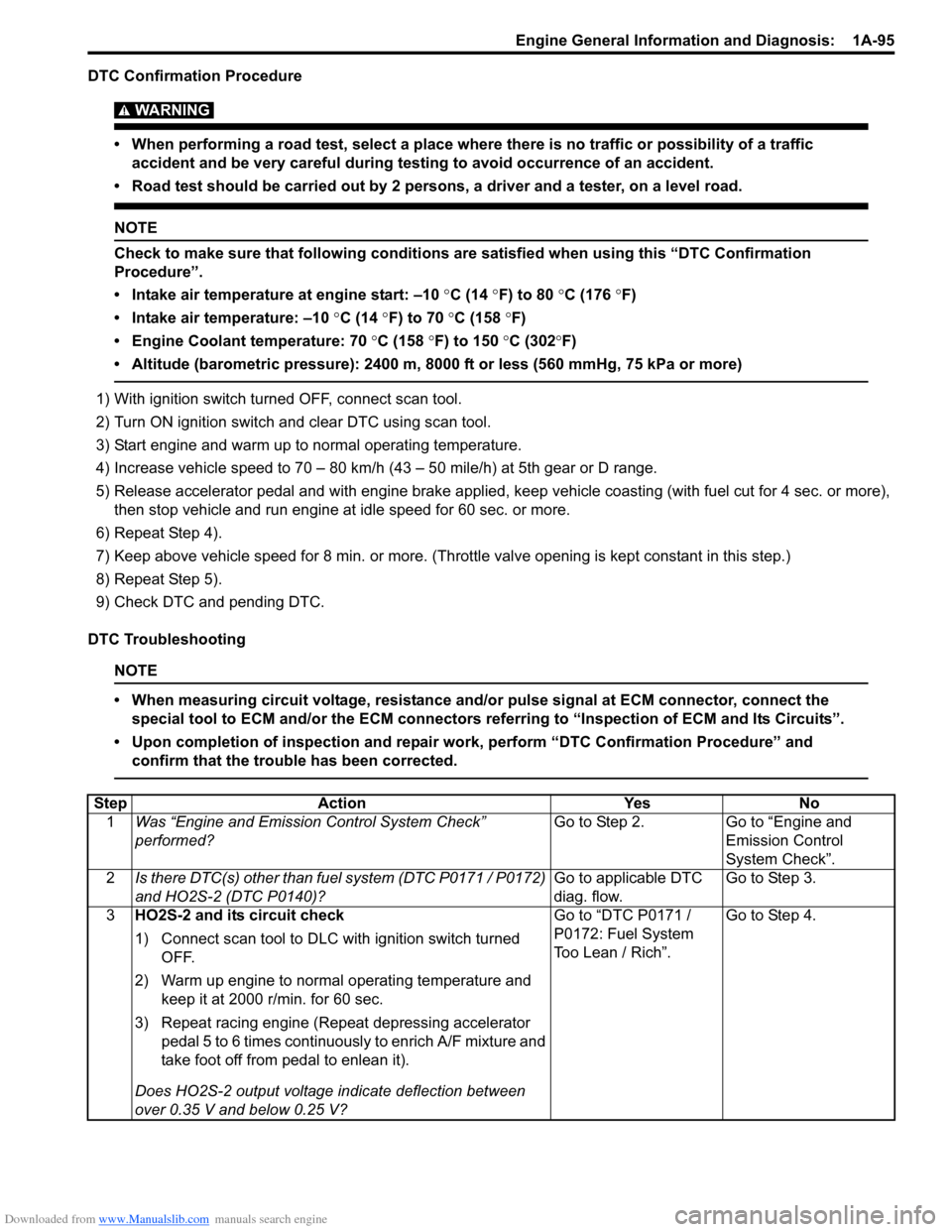
DTC Confirmation Procedure
WARNING!
• When performing a road test, select a place where there is no traffic or possibility of a traffic accident and be very careful during testing to avoid occurrence of an accident.
• Road test should be carried out by 2 persons, a driver and a tester, on a level road.
NOTE
Check to make sure that following conditions ar e satisfied when using this “DTC Confirmation
Procedure”.
• Intake air temperature at engine start: –10 °C (14 ° F) to 80 °C (176 °F)
• Intake air temperature: –10 °C (14 °F) to 70 °C (158 °F)
• Engine Coolant temperature: 70 °C (158 °F) to 150 °C (302 °F)
• Altitude (barometric pressure): 2400 m, 8000 ft or less (560 mmHg, 75 kPa or more)
1) With ignition switch turned OFF, connect scan tool.
2) Turn ON ignition switch and clear DTC using scan tool.
3) Start engine and warm up to normal operating temperature.
4) Increase vehicle speed to 70 – 80 km/h (43 – 50 mile/h) at 5th gear or D range.
5) Release accelerator pedal and with engine brake applied, ke ep vehicle coasting (with fuel cut for 4 sec. or more),
then stop vehicle and run engine at idle speed for 60 sec. or more.
6) Repeat Step 4).
7) Keep above vehicle speed for 8 min. or more. (Throt tle valve opening is kept constant in this step.)
8) Repeat Step 5).
9) Check DTC and pending DTC.
DTC Troubleshooting
NOTE
• When measuring circuit voltage, resistance and/ or pulse signal at ECM connector, connect the
special tool to ECM and/or the ECM connectors re ferring to “Inspection of ECM and Its Circuits”.
• Upon completion of inspection and repair work, perform “DTC Confirmation Procedure” and confirm that the trouble has been corrected.
Step Action YesNo
1 Was “Engine and Emission Control System Check”
performed? Go to Step 2.
Go to “Engine and
Emission Control
System Check”.
2 Is there DTC(s) other than fuel system (DTC P0171 / P0172)
and HO2S-2 (DTC P0140)? Go to applicable DTC
diag. flow.Go to Step 3.
3 HO2S-2 and its circuit check
1) Connect scan tool to DLC with ignition switch turned
OFF.
2) Warm up engine to normal operating temperature and keep it at 2000 r/min. for 60 sec.
3) Repeat racing engine (Repeat depressing accelerator pedal 5 to 6 times continuous ly to enrich A/F mixture and
take foot off from pedal to enlean it).
Does HO2S-2 output voltage indicate deflection between
over 0.35 V and below 0.25 V? Go to “DTC P0171 /
P0172: Fuel System
Too Lean / Rich”.
Go to Step 4.
Page 167 of 1496
Downloaded from www.Manualslib.com manuals search engine Engine General Information and Diagnosis: 1A-117
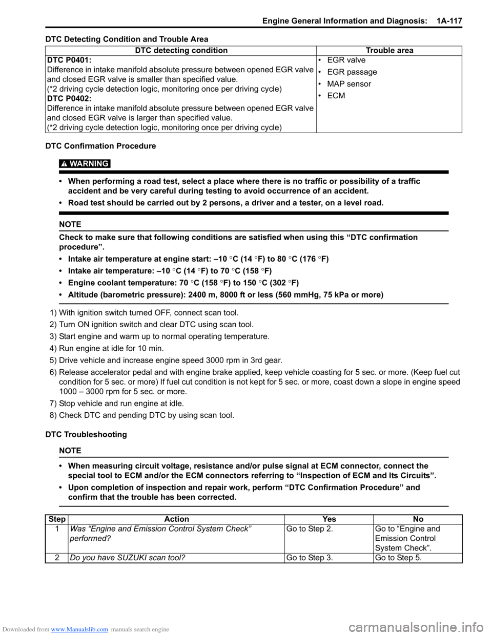
DTC Detecting Condition and Trouble Area
DTC Confirmation Procedure
WARNING!
• When performing a road test, select a place where there is no traffic or possibility of a traffic accident and be very careful during testing to avoid occurrence of an accident.
• Road test should be carried out by 2 persons, a driver and a tester, on a level road.
NOTE
Check to make sure that following conditions ar e satisfied when using this “DTC confirmation
procedure”.
• Intake air temperature at engine start: –10 °C (14 ° F) to 80 °C (176 °F)
• Intake air temperature: –10 °C (14 °F) to 70 °C (158 °F)
• Engine coolant temperature: 70 °C (158 °F) to 150 °C (302 °F)
• Altitude (barometric pressure): 2400 m, 8000 ft or less (560 mmHg, 75 kPa or more)
1) With ignition switch turned OFF, connect scan tool.
2) Turn ON ignition switch and clear DTC using scan tool.
3) Start engine and warm up to normal operating temperature.
4) Run engine at idle for 10 min.
5) Drive vehicle and increase engine speed 3000 rpm in 3rd gear.
6) Release accelerator pedal and with engine brake applied, keep vehicle coasting for 5 sec. or more. (Keep fuel cut condition for 5 sec. or more) If fuel cut condition is not ke pt for 5 sec. or more, coast down a slope in engine speed
1000 – 3000 rpm for 5 sec. or more.
7) Stop vehicle and run engine at idle.
8) Check DTC and pending DTC by using scan tool.
DTC Troubleshooting
NOTE
• When measuring circuit voltage, resistance and/ or pulse signal at ECM connector, connect the
special tool to ECM and/or the ECM connectors re ferring to “Inspection of ECM and Its Circuits”.
• Upon completion of inspection and repair work, perform “DTC Confirmation Procedure” and confirm that the trouble has been corrected.
DTC detecting condition Trouble area
DTC P0401:
Difference in intake manifold absolute pressure between opened EGR valve
and closed EGR valve is smaller than specified value.
(*2 driving cycle detection logic, monitoring once per driving cycle)
DTC P0402:
Difference in intake manifold absolute pressure between opened EGR valve
and closed EGR valve is la rger than specified value.
(*2 driving cycle detection logic, monitoring once per driving cycle) •EGR valve
• EGR passage
• MAP sensor
•ECM
Step
Action YesNo
1 Was “Engine and Emission Control System Check”
performed? Go to Step 2.
Go to “Engine and
Emission Control
System Check”.
2 Do you have SUZUKI scan tool? Go to Step 3.Go to Step 5.
Page 168 of 1496
Downloaded from www.Manualslib.com manuals search engine 1A-118 Engine General Information and Diagnosis:
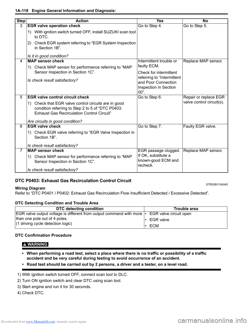
DTC P0403: Exhaust Gas Recirculation Control CircuitS7RS0B1104045
Wiring Diagram
Refer to “DTC P0401 / P0402: Exhaust Gas Recirculation Flow Insufficient Detected / Excessive Detected”.
DTC Detecting Condition and Trouble Area
DTC Confirmation Procedure
WARNING!
• When performing a road test, select a place where there is no traffic or possibility of a traffic accident and be very careful during testing to avoid occurrence of an accident.
• Road test should be carried out by 2 persons, a driver and a tester, on a level road.
1) With ignition switch turned OFF, connect scan tool to DLC.
2) Turn ON ignition switch and clear DTC using scan tool.
3) Start engine and run it for 30 seconds.
4) Check DTC. 3
EGR valve operation check
1) With ignition switch turned OF F, install SUZUKI scan tool
to DTC.
2) Check EGR system referring to “EGR System Inspection
in Section 1B”.
Is it in good condition? Go to Step 4. Go to Step 5.
4 MAP sensor check
1) Check MAP sensor for performance referring to “MAP
Sensor Inspection in Section 1C”.
Is check result satisfactory? Intermittent trouble or
faulty ECM.
Check for intermittent
referring to “Intermittent
and Poor Connection
Inspection in Section
00”.Replace MAP sensor.
5 EGR valve control circuit check
1) Check that EGR valve control circuits are in good
condition referring to Step 2 to 5 of “DTC P0403:
Exhaust Gas Recirculation Control Circuit”
Are circuits in good condition? Go to Step 6. Repair or replace EGR
valve control circuit(s).
6 EGR valve check
1) Check EGR valve referring to “EGR Valve Inspection in
Section 1B”.
Is check result satisfactory? Go to Step 7. Faulty EGR valve.
7 MAP sensor check
1) Check MAP sensor for performance referring to “MAP
Sensor Inspection in Section 1C”.
Is check result satisfactory? EGR passage clogged.
If OK, substitute a
known-good ECM and
recheck.
Replace MAP sensor.
Step Action Yes No
DTC detecting condition
Trouble area
EGR valve output voltage is differ ent from output command with more
than one pole out of 4 poles.
(1 driving cycle detection logic) • EGR valve circuit open
•EGR valve
•ECM
Page 169 of 1496
Downloaded from www.Manualslib.com manuals search engine Engine General Information and Diagnosis: 1A-119
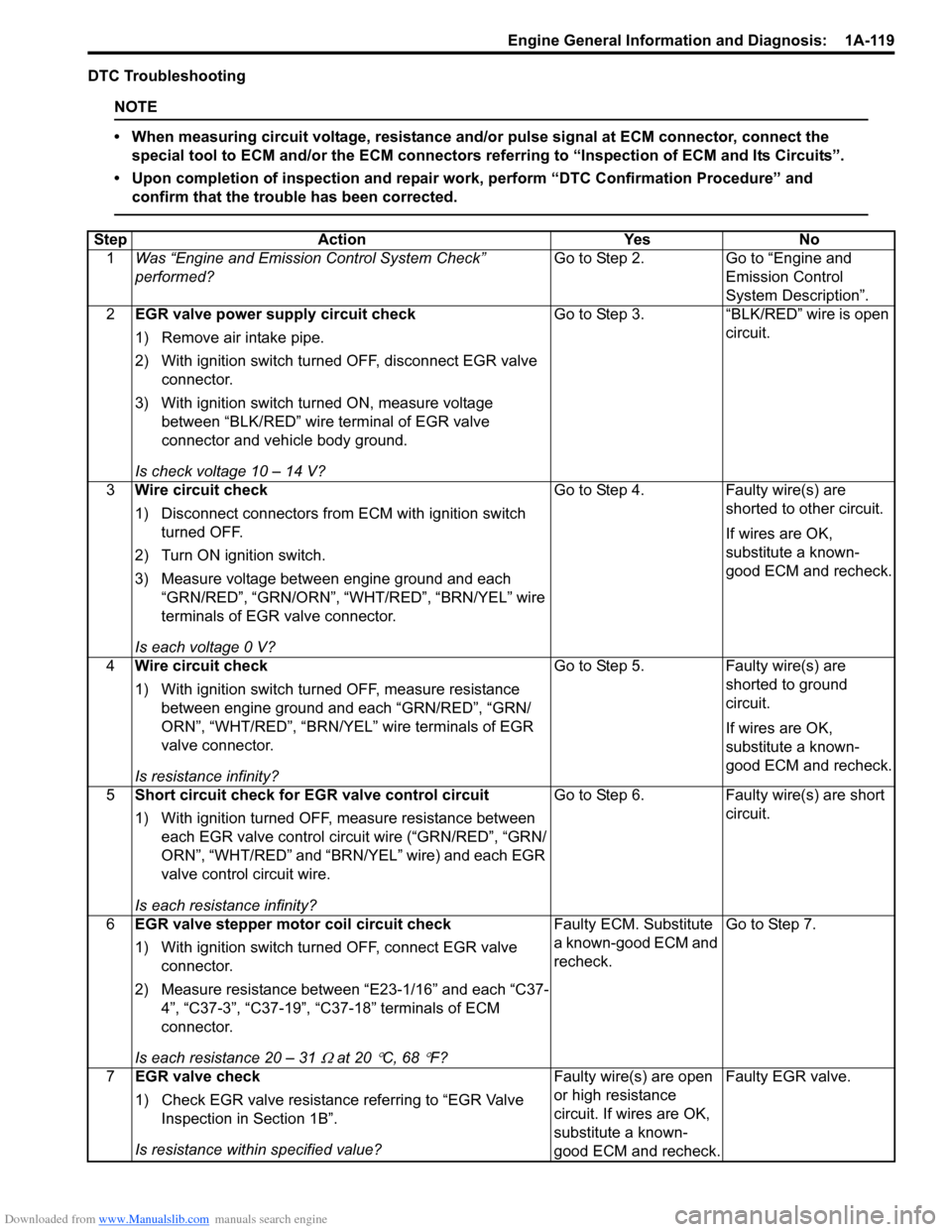
DTC Troubleshooting
NOTE
• When measuring circuit voltage, resistance and/or pulse signal at ECM connector, connect the
special tool to ECM and/or the ECM connectors re ferring to “Inspection of ECM and Its Circuits”.
• Upon completion of inspection and repair work, perform “DTC Confirmation Procedure” and confirm that the trouble has been corrected.
Step Action YesNo
1 Was “Engine and Emission Control System Check”
performed? Go to Step 2.
Go to “Engine and
Emission Control
System Description”.
2 EGR valve power supply circuit check
1) Remove air intake pipe.
2) With ignition switch turned OFF, disconnect EGR valve
connector.
3) With ignition switch turned ON, measure voltage between “BLK/RED” wire terminal of EGR valve
connector and vehicle body ground.
Is check voltage 10 – 14 V? Go to Step 3.
“BLK/RED” wire is open
circuit.
3 Wire circuit check
1) Disconnect connectors from ECM with ignition switch
turned OFF.
2) Turn ON ignition switch.
3) Measure voltage between engine ground and each “GRN/RED”, “GRN/ORN”, “W HT/RED”, “BRN/YEL” wire
terminals of EGR valve connector.
Is each voltage 0 V? Go to Step 4.
Faulty wire(s) are
shorted to other circuit.
If wires are OK,
substitute a known-
good ECM and recheck.
4 Wire circuit check
1) With ignition switch turned OFF, measure resistance
between engine ground and each “GRN/RED”, “GRN/
ORN”, “WHT/RED”, “BRN/YEL” wire terminals of EGR
valve connector.
Is resistance infinity? Go to Step 5.
Faulty wire(s) are
shorted to ground
circuit.
If wires are OK,
substitute a known-
good ECM and recheck.
5 Short circuit check for EGR valve control circuit
1) With ignition turned OFF, measure resistance between
each EGR valve control circ uit wire (“GRN/RED”, “GRN/
ORN”, “WHT/RED” and “BRN/ YEL” wire) and each EGR
valve control circuit wire.
Is each resistance infinity? Go to Step 6.
Faulty wire(s) are short
circuit.
6 EGR valve stepper motor coil circuit check
1) With ignition switch turned OFF, connect EGR valve
connector.
2) Measure resistance between “E23-1/16” and each “C37- 4”, “C37-3”, “C37-19”, “C37-18” terminals of ECM
connector.
Is each resistance 20 – 31
Ω at 20 °C, 68 °F? Faulty ECM. Substitute
a known-good ECM and
recheck.
Go to Step 7.
7 EGR valve check
1) Check EGR valve resistance referring to “EGR Valve
Inspection in Section 1B”.
Is resistance within specified value? Faulty wire(s) are open
or high resistance
circuit. If wires are OK,
substitute a known-
good ECM and recheck.Faulty EGR valve.
Page 171 of 1496
Downloaded from www.Manualslib.com manuals search engine Engine General Information and Diagnosis: 1A-121
DTC Detecting Condition and Trouble Area
DTC Confirmation Procedure
WARNING!
• When performing a road test, select a place where there is no traffic or possibility of a traffic accident and be very careful during testing to avoid occurrence of an accident.
• Road test should be carried out by 2 persons, a driver and a tester, on a level road.
NOTE
Check to make sure that following conditions ar e satisfied when using this “DTC Confirmation
Procedure”.
• Intake air temperature at engine start: –10 °C (14 ° F) to 80 °C (176 °F)
• Intake air temperature: –10 °C (14 °F) to 70 °C (158 °F)
• Engine coolant temp.: 70 °C, 158 °F to 150 °C (302 °F)
• Altitude (barometric pressure): 2400 m, 8000 ft or less (500 mmHg, 75 kPa or more)
1) Connect scan tool to DLC with ignition switch turned OFF.
2) Turn ON ignition switch and clear DTC using scan tool.
3) Increase vehicle speed to 37 – 62 mph, 60 – 100 km/h. (engine speed: 2500 – 3000 r/min.)
4) Keep above vehicle speed for 10 min. or more (Thr ottle valve opening is kept constant in this step).
5) Stop vehicle and check if DTC / pending DTC exists using sc an tool. If not, check if catalyst monitoring test has
been completed using scan tool. If not in both of above checks (i.e., no DTC / pending DTC and catalyst
monitoring test not completed), check vehicle cond ition (environmental) and repeat Step 3) through 5).
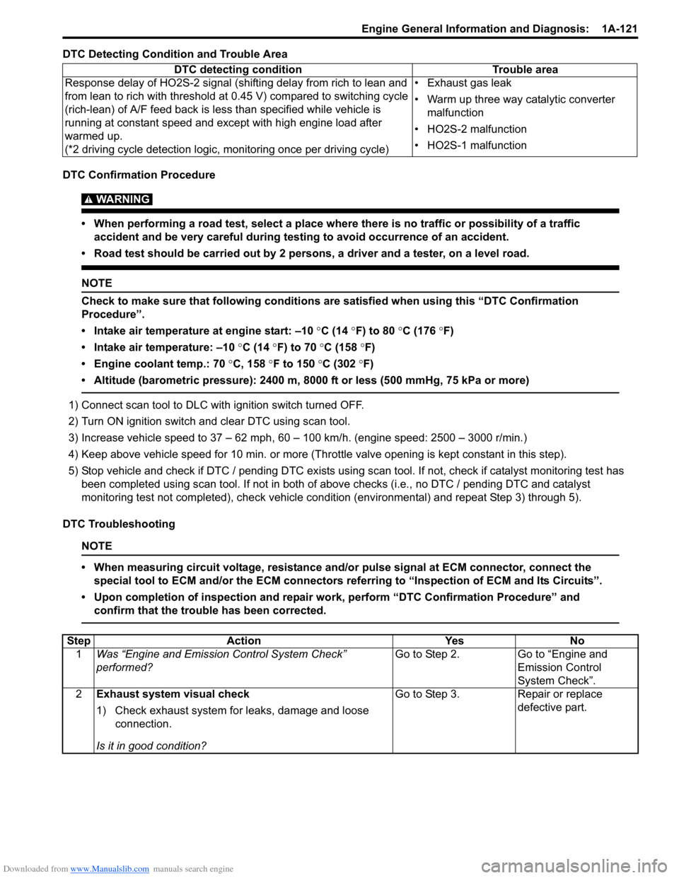
DTC Troubleshooting
NOTE
• When measuring circuit voltage, resistance and/ or pulse signal at ECM connector, connect the
special tool to ECM and/or the ECM connectors re ferring to “Inspection of ECM and Its Circuits”.
• Upon completion of inspection and repair work, perform “DTC Confirmation Procedure” and confirm that the trouble has been corrected.
DTC detecting condition Trouble area
Response delay of HO2S-2 signal (shifting delay from rich to lean and
from lean to rich with threshold at 0.45 V) compared to switching cycle
(rich-lean) of A/F feed back is less than specified while vehicle is
running at constant speed and except with high engine load after
warmed up.
(*2 driving cycle detection logic, monitoring once per driving cycle) • Exhaust gas leak
• Warm up three way catalytic converter
malfunction
• HO2S-2 malfunction
• HO2S-1 malfunction
Step Action YesNo
1 Was “Engine and Emission Control System Check”
performed? Go to Step 2.
Go to “Engine and
Emission Control
System Check”.
2 Exhaust system visual check
1) Check exhaust system for leaks, damage and loose
connection.
Is it in good condition? Go to Step 3.
Repair or replace
defective part.
Page 173 of 1496
Downloaded from www.Manualslib.com manuals search engine Engine General Information and Diagnosis: 1A-123
DTC Confirmation Procedure
WARNING!
• When performing a road test, select a place where there is no traffic or possibility of a traffic accident and be very careful during testing to avoid occurrence of an accident.
• Road test should be carried out by 2 persons, a driver and a tester, on a level road.
1) With ignition switch OFF, connect scan tool to DLC.
2) Turn ON ignition switch and clear DTC using scan tool.
3) Start engine and warm up normal operating temperature.
4) Drive vehicle at more than 40 km/h, 25 mph for 5 min. or more.
5) Check DTC and pending DTC.
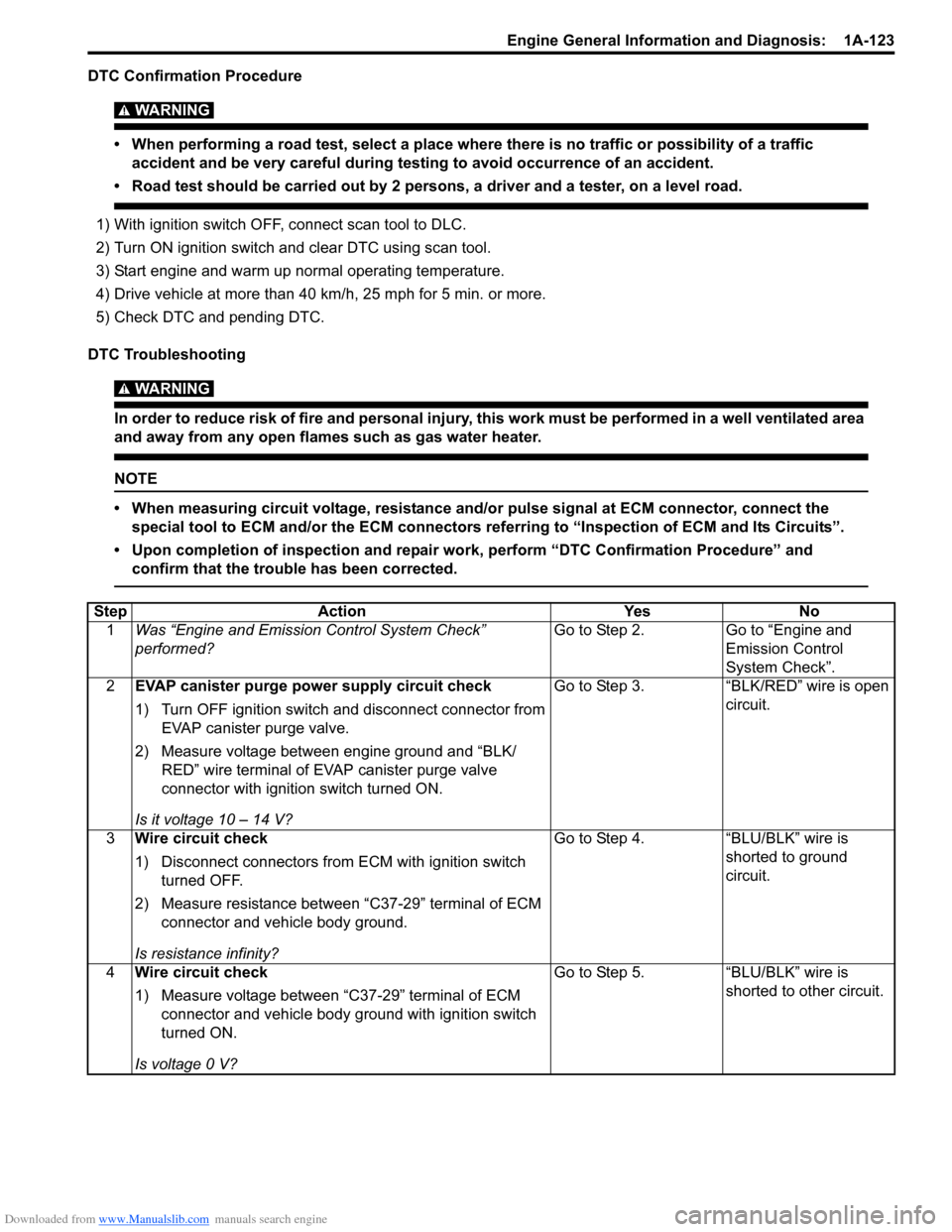
DTC Troubleshooting
WARNING!
In order to reduce risk of fire and personal injury, this work must be performed in a well ventilated area
and away from any open flames such as gas water heater.
NOTE
• When measuring circuit voltage, resistance and/ or pulse signal at ECM connector, connect the
special tool to ECM and/or the ECM connectors re ferring to “Inspection of ECM and Its Circuits”.
• Upon completion of inspection and repair work, perform “DTC Confirmation Procedure” and confirm that the trouble has been corrected.
Step Action YesNo
1 Was “Engine and Emission Control System Check”
performed? Go to Step 2.
Go to “Engine and
Emission Control
System Check”.
2 EVAP canister purge power supply circuit check
1) Turn OFF ignition switch and disconnect connector from
EVAP canister purge valve.
2) Measure voltage between engine ground and “BLK/ RED” wire terminal of EVAP canister purge valve
connector with ignition switch turned ON.
Is it voltage 10 – 14 V? Go to Step 3.
“BLK/RED” wire is open
circuit.
3 Wire circuit check
1) Disconnect connectors from ECM with ignition switch
turned OFF.
2) Measure resistance between “C37-29” terminal of ECM connector and vehicle body ground.
Is resistance infinity? Go to Step 4.
“BLU/BLK” wire is
shorted to ground
circuit.
4 Wire circuit check
1) Measure voltage between “C37-29” terminal of ECM
connector and vehicle body ground with ignition switch
turned ON.
Is voltage 0 V? Go to Step 5.
“BLU/BLK” wire is
shorted to other circuit.
Page 206 of 1496
Downloaded from www.Manualslib.com manuals search engine 1A-156 Engine General Information and Diagnosis:
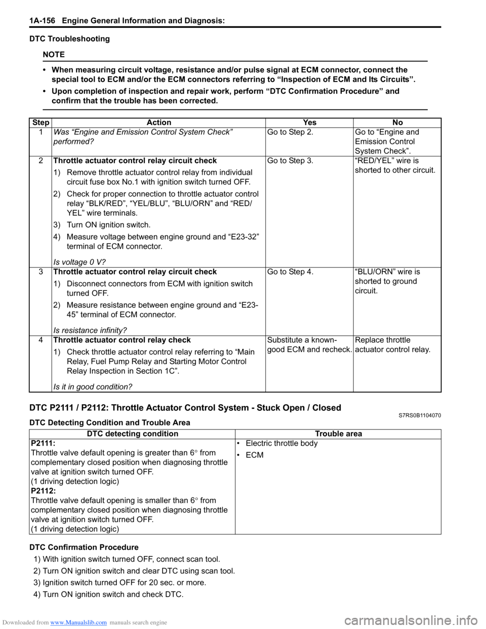
DTC Troubleshooting
NOTE
• When measuring circuit voltage, resistance and/or pulse signal at ECM connector, connect the
special tool to ECM and/or the ECM connectors re ferring to “Inspection of ECM and Its Circuits”.
• Upon completion of inspection and repair work, perform “DTC Confirmation Procedure” and confirm that the trouble has been corrected.
DTC P2111 / P2112: Throttle Actuator Control System - Stuck Open / ClosedS7RS0B1104070
DTC Detecting Condition and Trouble Area
DTC Confirmation Procedure
1) With ignition switch turned OFF, connect scan tool.
2) Turn ON ignition switch and clear DTC using scan tool.
3) Ignition switch turned OFF for 20 sec. or more.
4) Turn ON ignition switch and check DTC.
Step Action Yes No
1 Was “Engine and Emission Control System Check”
performed? Go to Step 2. Go to “Engine and
Emission Control
System Check”.
2 Throttle actuator cont rol relay circuit check
1) Remove throttle actuator co ntrol relay from individual
circuit fuse box No.1 with ignition switch turned OFF.
2) Check for proper connection to throttle actuator control relay “BLK/RED”, “YEL/BLU”, “BLU/ORN” and “RED/
YEL” wire terminals.
3) Turn ON ignition switch.
4) Measure voltage between engine ground and “E23-32” terminal of ECM connector.
Is voltage 0 V? Go to Step 3. “RED/YEL” wire is
shorted to other circuit.
3 Throttle actuator cont rol relay circuit check
1) Disconnect connectors from ECM with ignition switch turned OFF.
2) Measure resistance between engine ground and “E23- 45” terminal of ECM connector.
Is resistance infinity? Go to Step 4. “BLU/ORN” wire is
shorted to ground
circuit.
4 Throttle actuator control relay check
1) Check throttle actuator control relay referring to “Main Relay, Fuel Pump Relay an d Starting Motor Control
Relay Inspection in Section 1C”.
Is it in good condition? Substitute a known-
good ECM and recheck.
Replace throttle
actuator control relay.
DTC detecting condition
Trouble area
P2111:
Throttle valve default opening is greater than 6 ° from
complementary closed position when diagnosing throttle
valve at ignition switch turned OFF.
(1 driving detection logic)
P2112:
Throttle valve default opening is smaller than 6 ° from
complementary closed position when diagnosing throttle
valve at ignition switch turned OFF.
(1 driving detection logic) • Electric throttle body
•ECM
Page 207 of 1496
Downloaded from www.Manualslib.com manuals search engine Engine General Information and Diagnosis: 1A-157
DTC Troubleshooting
NOTE
• When measuring circuit voltage, resistance and/or pulse signal at ECM connector, connect the
special tool to ECM and/or the ECM connectors re ferring to “Inspection of ECM and Its Circuits”.
• Upon completion of inspection and repair work, perform “DTC Confirmation Procedure” and confirm that the trouble has been corrected.
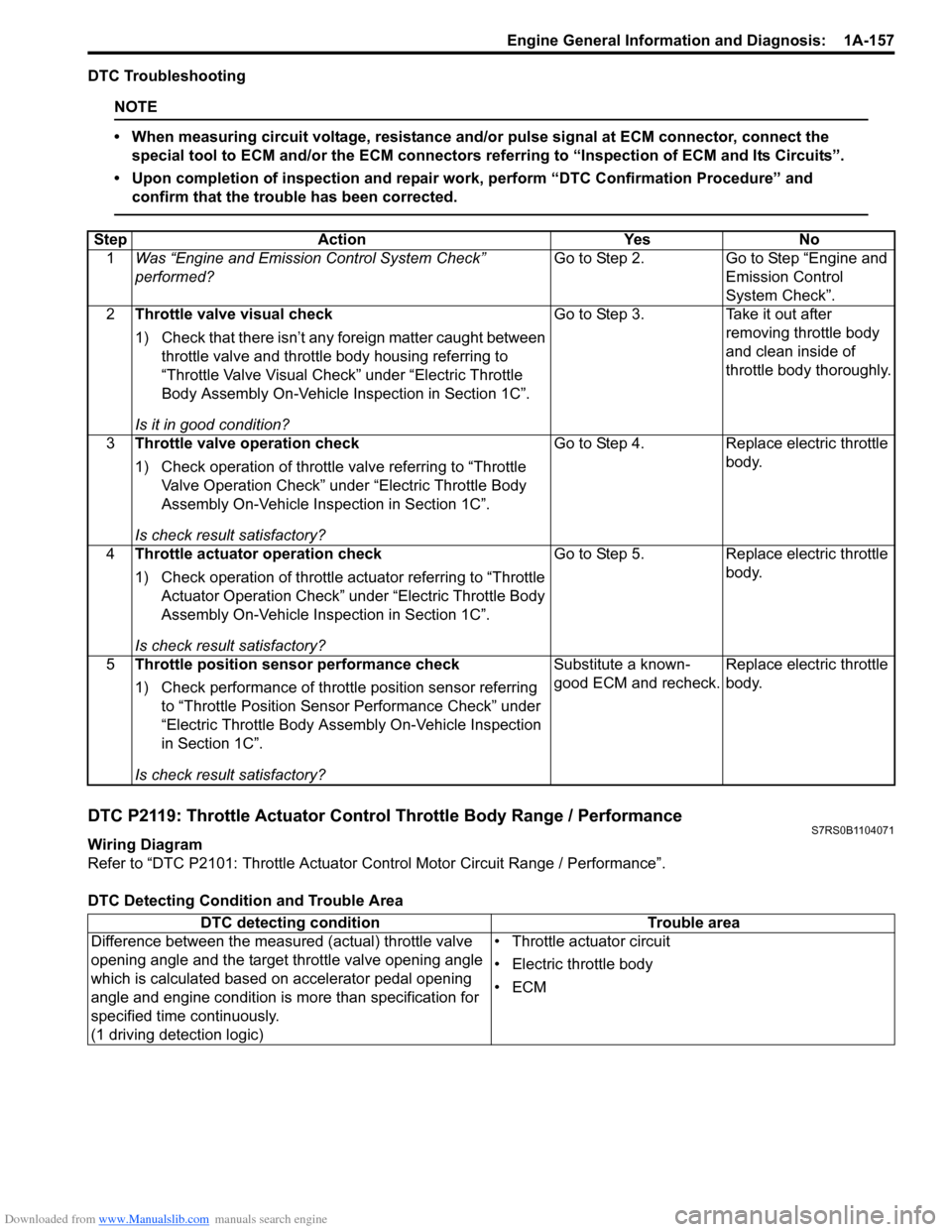
DTC P2119: Throttle Actuator Control Throttle Body Range / PerformanceS7RS0B1104071
Wiring Diagram
Refer to “DTC P2101: Throttle Actuator Control Motor Circuit Range / Performance”.
DTC Detecting Condition and Trouble Area Step Action Yes No
1 Was “Engine and Emission Control System Check”
performed? Go to Step 2. Go to Step “Engine and
Emission Control
System Check”.
2 Throttle valve visual check
1) Check that there isn’t any foreign matter caught between
throttle valve and throttle body housing referring to
“Throttle Valve Visual Check” under “Electric Throttle
Body Assembly On-Vehicle Inspection in Section 1C”.
Is it in good condition? Go to Step 3. Take it out after
removing throttle body
and clean inside of
throttle body thoroughly.
3 Throttle valve operation check
1) Check operation of throttle valve referring to “Throttle
Valve Operation Check” under “Electric Throttle Body
Assembly On-Vehicle Inspection in Section 1C”.
Is check result satisfactory? Go to Step 4. Replace electric throttle
body.
4 Throttle actuator operation check
1) Check operation of throttle ac tuator referring to “Throttle
Actuator Operation Check” under “Electric Throttle Body
Assembly On-Vehicle Inspection in Section 1C”.
Is check result satisfactory? Go to Step 5. Replace electric throttle
body.
5 Throttle position sensor performance check
1) Check performance of throttle position sensor referring
to “Throttle Position Sensor Performance Check” under
“Electric Throttle Body Assembly On-Vehicle Inspection
in Section 1C”.
Is check result satisfactory? Substitute a known-
good ECM and recheck.
Replace electric throttle
body.
DTC detecting condition
Trouble area
Difference between the measured (actual) throttle valve
opening angle and the target throttle valve opening angle
which is calculated based on accelerator pedal opening
angle and engine condition is more than specification for
specified time continuously.
(1 driving detection logic) • Throttle actuator circuit
• Electric throttle body
•ECM
Page 243 of 1496
Downloaded from www.Manualslib.com manuals search engine Engine General Information and Diagnosis: 1A-193
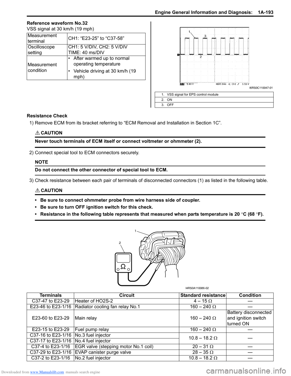
Reference waveform No.32
VSS signal at 30 km/h (19 mph)
Resistance Check1) Remove ECM from its bracket referring to “ECM Removal and Installation in Section 1C”.
CAUTION!
Never touch terminals of ECM itself or connect voltmeter or ohmmeter (2).
2) Connect special tool to ECM connectors securely.
NOTE
Do not connect the other connector of special tool to ECM.
3) Check resistance between each pair of terminals of disconnected connectors (1) as listed in the following table.
CAUTION!
• Be sure to connect ohmmeter probe from wire harness side of coupler.
• Be sure to turn OFF ignition switch for this check.
• Resistance in the following table represents that measured when parts temperature is 20 °C (68 °F).
Measurement
terminal CH1: “E23-25” to “C37-58”
Oscilloscope
setting CH1: 5 V/DIV, CH2: 5 V/DIV
TIME: 40 ms/DIV
Measurement
condition • After warmed up to normal
operating temperature
• Vehicle driving at 30 km/h (19 mph)
1. VSS signal for EPS control module
2. ON
3. OFF
I6RS0C110047-01
1
2
I4RS0A110086-02
Terminals CircuitStandard resistance Condition
C37-47 to E23-29 Heater of HO2S-2 4 – 15 Ω—
E23-46 to E23-1/16 Radiator cooling fan relay No.1 160 – 240 Ω —
E23-60 to E23-29 Main relay 160 – 240 ΩBattery disconnected
and ignition switch
turned ON
E23-15 to E23-29 Fuel pump relay 160 – 240 Ω —
C37-16 to E23-1/16 No.3 fuel injector 10.8 – 18.2 Ω —
C37-17 to E23-1/16 No.4 fuel injector
C37-4 to E23-1/16 EGR valve (st epping motor No.1 coil) 20 – 31 Ω —
C37-29 to E23-1/16 EVAP canister purge valve 28 – 35 Ω —
C37-2 to E23-1/16 No.2 fuel injector 10.8 – 18.2 Ω—