Generator SUZUKI SWIFT 2006 2.G Service Service Manual
[x] Cancel search | Manufacturer: SUZUKI, Model Year: 2006, Model line: SWIFT, Model: SUZUKI SWIFT 2006 2.GPages: 1496, PDF Size: 34.44 MB
Page 417 of 1496
Downloaded from www.Manualslib.com manuals search engine Charging System: 1J-7
With Charging Equipment
CAUTION!
When jump starting engine with charging
equipment, be sure equipment used is 12-
volt and negative ground. Do not use 24-volt
charging equipment. Using such equipment
can cause serious damage to electrical
system or electronic parts.
Battery Dismounting and RemountingS7RS0B1A06002
WARNING!
When handling battery, following safety
precautions should be followed:
• Hydrogen gas is produced by battery. A flame or spark near battery may cause the
gas to ignite.
• Battery fluid is highly acidic. Avoid spilling on clothing or other fabric. Any spilled
electrolyte should be flushed with large
quantity of water and cleaned immediately.
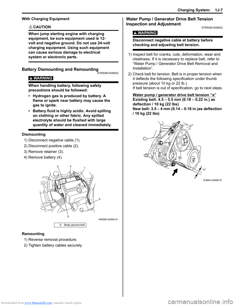
Dismounting
1) Disconnect negative cable (1).
2) Disconnect positive cable (2).
3) Remove retainer (3).
4) Remove battery (4).
Remounting 1) Reverse removal procedure.
2) Tighten battery cables securely.
Water Pump / Generator Drive Belt Tension
Inspection and Adjustment
S7RS0B1A06003
WARNING!
Disconnect negative cable at battery before
checking and adjusting belt tension.
1) Inspect belt for cranks, cuts, deformation, wear and clealiness. If it is necessary to replace belt, refer to
“Water Pump / Generator Drive Belt Removal and
Installation”.
2) Check belt for tension. Belt is in proper tension when it deflects the following specification under thumb
pressure (about 10 kg or 22 lb.).
If belt tension is out of spec ification, go to next steps.
Water pump / generator drive belt tension
“a”
Existing belt: 4.5 – 5.5 mm (0.18 – 0.22 in.) as
deflection / 10 kg (22 lbs)
New belt: 3.5 – 4 mm (0.14 – 0.16 in.)as deflection
/ 10 kg (22 lbs)
5. Body ground bolt
1
3 5
2
4
I4RS0B1A0006-01
“a”
I5JB0A1A0008-01
Page 418 of 1496
Downloaded from www.Manualslib.com manuals search engine 1J-8 Charging System:
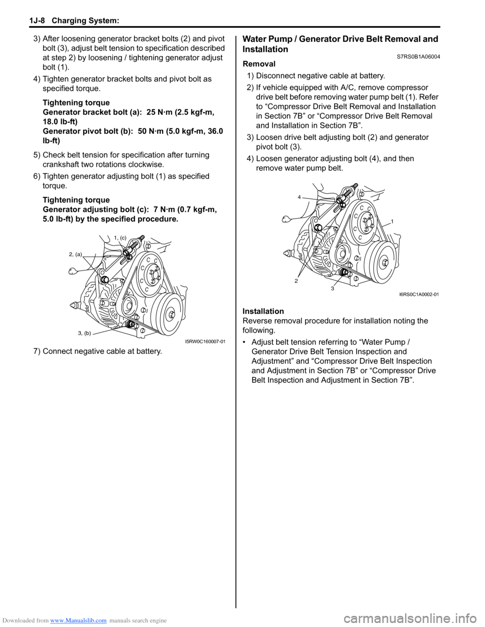
3) After loosening generator bracket bolts (2) and pivot bolt (3), adjust belt tensio n to specification described
at step 2) by loosening / tightening generator adjust
bolt (1).
4) Tighten generator bracket bolts and pivot bolt as specified torque.
Tightening torque
Generator bracket bolt (a): 25 N·m (2.5 kgf-m,
18.0 lb-ft)
Generator pivot bolt (b): 50 N·m (5.0 kgf-m, 36.0
lb-ft)
5) Check belt tension for specification after turning crankshaft two rotations clockwise.
6) Tighten generator adjusting bolt (1) as specified torque.
Tightening torque
Generator adjusting bolt (c): 7 N·m (0.7 kgf-m,
5.0 lb-ft) by the specified procedure.
7) Connect negative cable at battery.Water Pump / Generator Drive Belt Removal and
Installation
S7RS0B1A06004
Removal 1) Disconnect negative cable at battery.
2) If vehicle equipped with A/C, remove compressor drive belt before removing water pump belt (1). Refer
to “Compressor Drive Belt Removal and Installation
in Section 7B” or “Compr essor Drive Belt Removal
and Installation in Section 7B”.
3) Loosen drive belt adjusting bolt (2) and generator pivot bolt (3).
4) Loosen generator adjusting bolt (4), and then remove water pump belt.
Installation
Reverse removal procedure for installation noting the
following.
• Adjust belt tension referring to “Water Pump / Generator Drive Belt Tension Inspection and
Adjustment” and “Compressor Drive Belt Inspection
and Adjustment in Section 7B” or “Compressor Drive
Belt Inspection and Adjustment in Section 7B”.
1, (c)
2, (a)
3, (b)
I5RW0C160007-01
4
23
1
I6RS0C1A0002-01
Page 419 of 1496
Downloaded from www.Manualslib.com manuals search engine Charging System: 1J-9
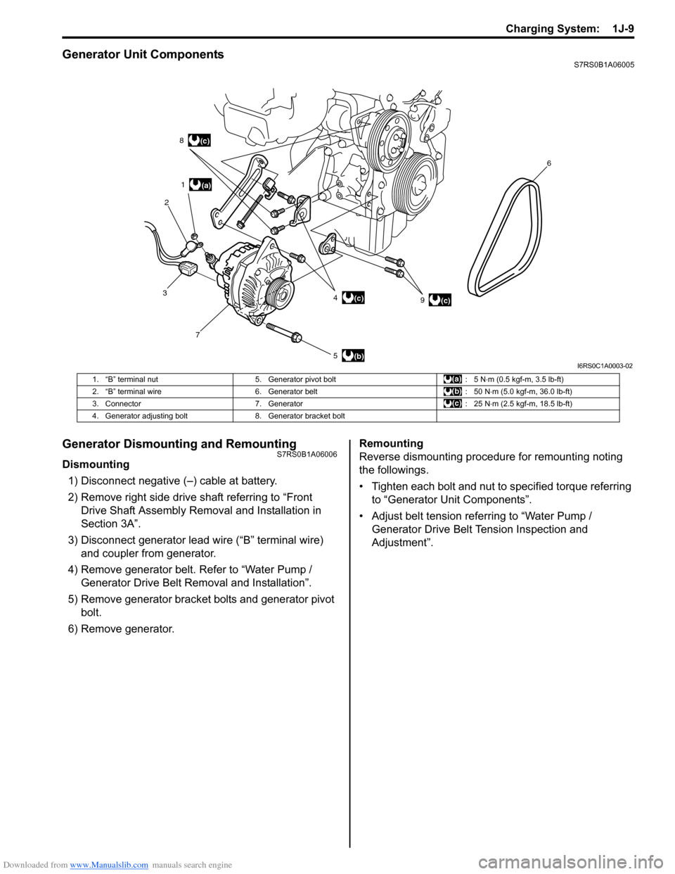
Generator Unit ComponentsS7RS0B1A06005
Generator Dismounting and RemountingS7RS0B1A06006
Dismounting1) Disconnect negative (–) cable at battery.
2) Remove right side drive shaft referring to “Front Drive Shaft Assembly Removal and Installation in
Section 3A”.
3) Disconnect generator lead wire (“B” terminal wire) and coupler from generator.
4) Remove generator belt. Refer to “Water Pump / Generator Drive Belt Re moval and Installation”.
5) Remove generator bracket bolts and generator pivot bolt.
6) Remove generator. Remounting
Reverse dismounting procedure for remounting noting
the followings.
• Tighten each bolt and nut to specified torque referring
to “Generator Unit Components”.
• Adjust belt tension referring to “Water Pump / Generator Drive Belt Tension Inspection and
Adjustment”.
(a)
(b)
(c)
1
2 8
3 7 5 49 6(c)
(c)
I6RS0C1A0003-02
1. “B” terminal nut
5. Generator pivot bolt : 5 N⋅m (0.5 kgf-m, 3.5 lb-ft)
2. “B” terminal wire 6. Generator belt : 50 N⋅m (5.0 kgf-m, 36.0 lb-ft)
3. Connector 7. Generator : 25 N⋅m (2.5 kgf-m, 18.5 lb-ft)
4. Generator adjusting bolt 8. Generator bracket bolt
Page 420 of 1496
Downloaded from www.Manualslib.com manuals search engine 1J-10 Charging System:
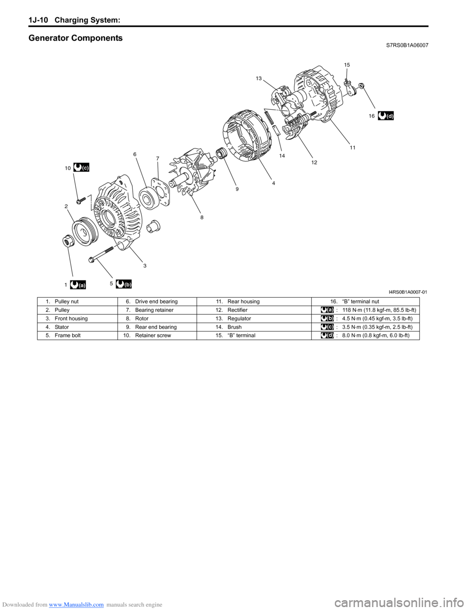
Generator ComponentsS7RS0B1A06007
1211
13
14
(a)(b)
(c)
(d)
1 2
3 4
56
7
89
10 15
16
I4RS0B1A0007-01
1. Pulley nut 6. Drive end bearing 11. Rear housing 16. “B” terminal nut
2. Pulley 7. Bearing retainer 12. Rectifier : 118 N⋅m (11.8 kgf-m, 85.5 lb-ft)
3. Front housing 8. Rotor 13. Regulator : 4.5 N⋅m (0.45 kgf-m, 3.5 lb-ft)
4. Stator 9. Rear end bearing 14. Brush : 3.5 N⋅m (0.35 kgf-m, 2.5 lb-ft)
5. Frame bolt 10. Retainer screw 15. “B” terminal : 8.0 N⋅m (0.8 kgf-m, 6.0 lb-ft)
Page 421 of 1496
Downloaded from www.Manualslib.com manuals search engine Charging System: 1J-11
Generator InspectionS7RS0B1A06008
Rotor
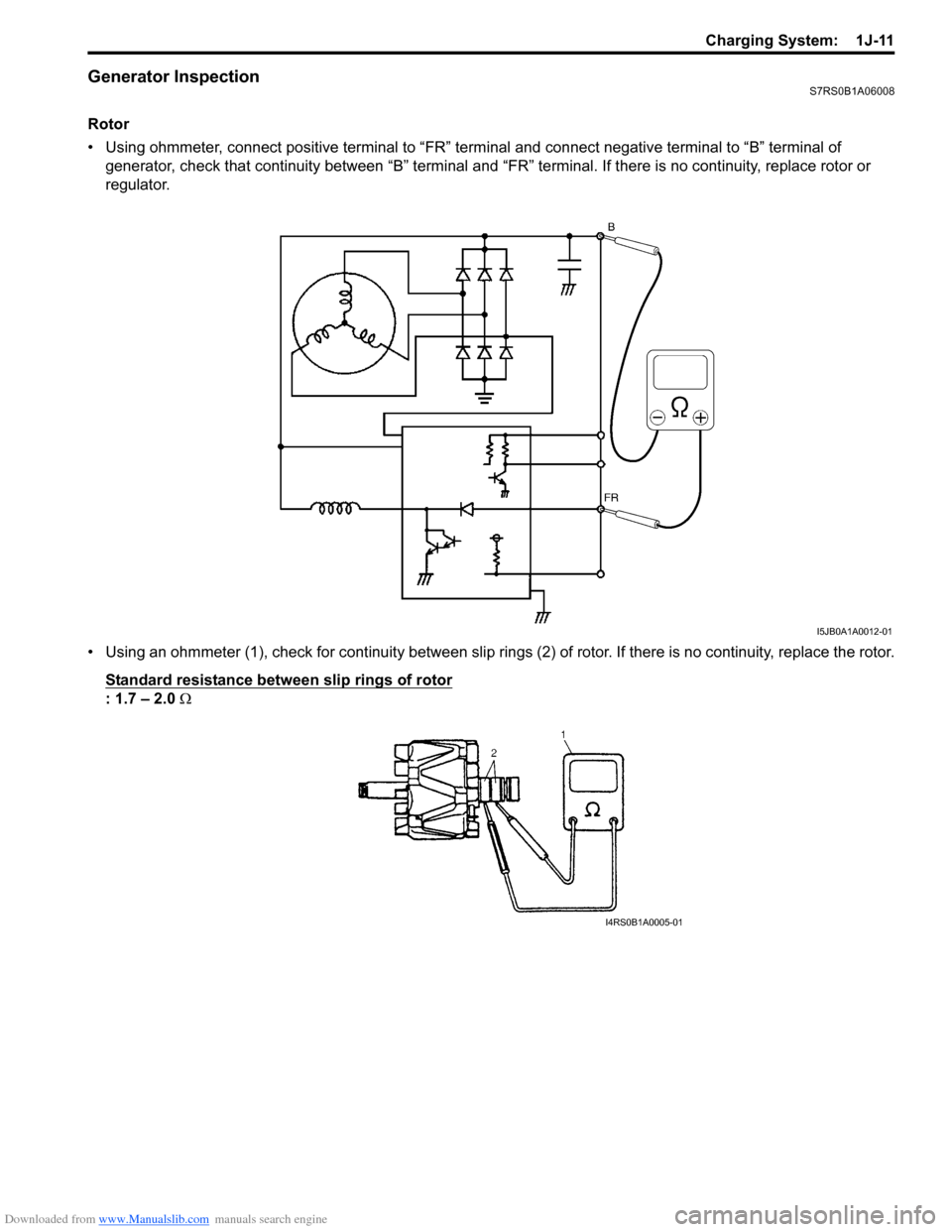
• Using ohmmeter, connect positive terminal to “FR” terminal and connect negative terminal to “B” terminal of generator, check that continuity between “B” terminal and “FR” terminal. If there is no continuity, replace rotor or
regulator.
• Using an ohmmeter (1), check for continuity between slip ring s (2) of rotor. If there is no continuity, replace the rotor.
Standard resistance between slip rings of rotor
: 1.7 – 2.0 Ω
I5JB0A1A0012-01
I4RS0B1A0005-01
Page 423 of 1496
Downloaded from www.Manualslib.com manuals search engine Charging System: 1J-13
Specifications
Charging System SpecificationsS7RS0B1A07001
Battery
Battery
: 48AH/20H, 40.6AH/5H 12 V
Generator
Tightening Torque SpecificationsS7RS0B1A07002
NOTE
The specified tightening torque is also described in the following.
“Generator Unit Components”
“Generator Components”
Reference:
For the tightening torque of fastener not specified in this section, refer to “Fasteners Information in Section 0A”.
Nominal output
12 V
Rated capacity 48 Ah/20 h
40.6 Ah/5 h
Cold cranking amperes 300 A (DIN)
Ty p e 80A type
Rated voltage 12 V
Nominal output 80A
Permissible max. speed 18,000 r/min.
No-load speed 1200 r/min. (rpm)
Regulated voltage 14.2 – 14.8 V at 25 ° C (77 °F)
Exposed brush length Standard: 16 mm (0.63 in.)
Limit: 5.0 mm (0.02 in.)
Permissible ambient temperature –30 to 100 °C (–22 to 212 °F)
Polarity Negative ground
Rotation Clockwise viewed from pulley side
Fastening partTightening torque
Note
N ⋅mkgf-mlb-ft
Generator bracket bolt 25 2.5 18.0 �)
Generator pivot bolt 50 5.0 36.0 �)
Generator adjusting bolt 70.7 5.0by the specified
procedure.
�)
Page 560 of 1496
Downloaded from www.Manualslib.com manuals search engine 4E-21 ABS:
DTC C1057: Power Source CircuitS7RS0B4504014
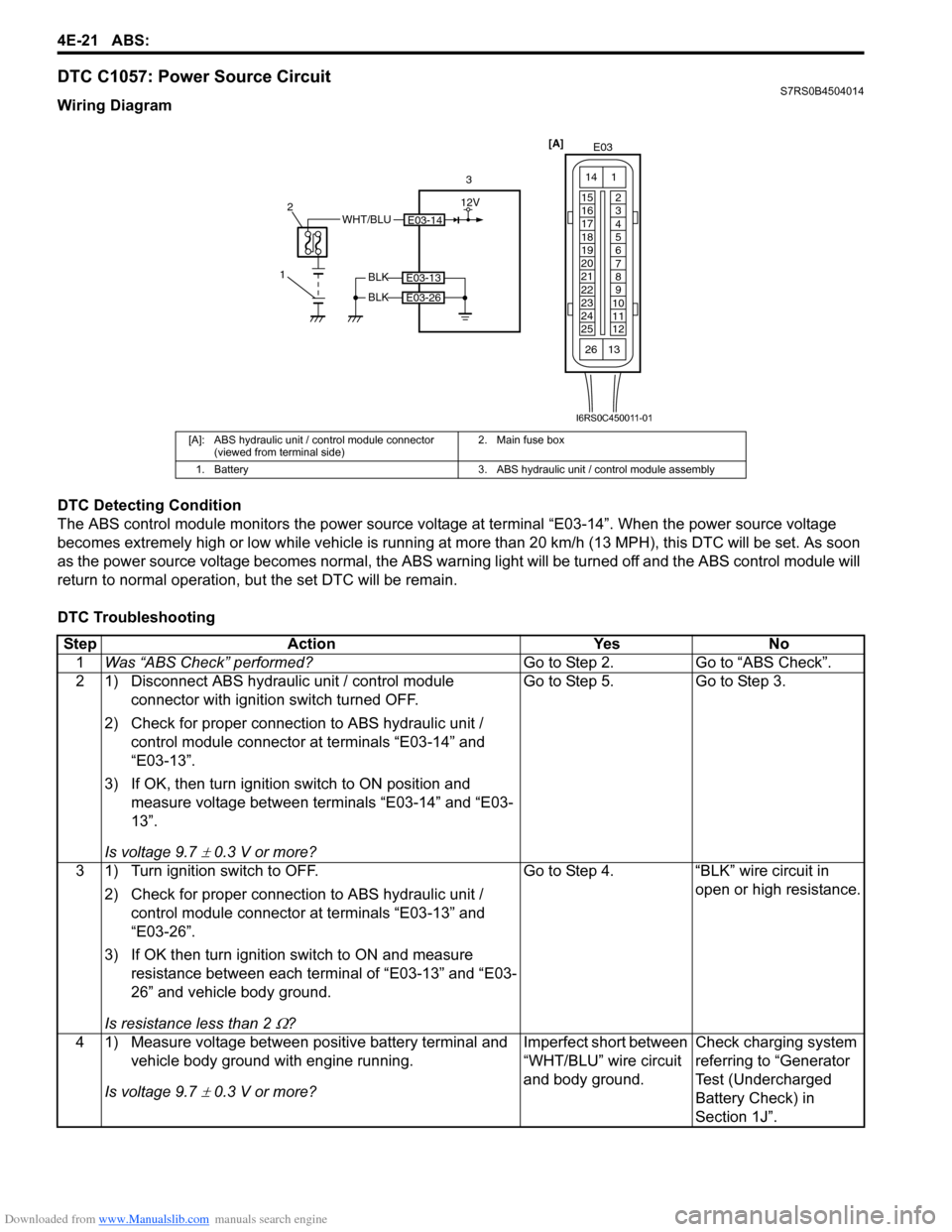
Wiring Diagram
DTC Detecting Condition
The ABS control module monitors the power source voltage at terminal “E03-14”. When the power source voltage
becomes extremely high or low while vehicle is running at more than 20 km/h (13 MPH), this DTC will be set. As soon
as the power source volta ge becomes normal, the ABS warning light will be turned off and the ABS control module will
return to normal operation, bu t the set DTC will be remain.
DTC Troubleshooting
[A]: ABS hydraulic unit / control module connector (viewed from terminal side) 2. Main fuse box
1. Battery 3. ABS hydraulic unit / control module assembly
E03-14WHT/BLU
1 2
3
BLK
BLK
E03-13
E03-26
[A]
E03
15
16
17
18
19
20
21
22
23
24
25 2
3
4
5
6
7
8
9
10
11
12
1
13
14
26
12V
I6RS0C450011-01
Step
Action YesNo
1 Was “ABS Check” performed? Go to Step 2.Go to “ABS Check”.
2 1) Disconnect ABS hydraulic unit / control module connector with ignition switch turned OFF.
2) Check for proper connection to ABS hydraulic unit / control module connector at terminals “E03-14” and
“E03-13”.
3) If OK, then turn ignition switch to ON position and measure voltage between terminals “E03-14” and “E03-
13”.
Is voltage 9.7
± 0.3 V or more? Go to Step 5. Go to Step 3.
3 1) Turn ignition switch to OFF. 2) Check for proper connection to ABS hydraulic unit / control module connector at terminals “E03-13” and
“E03-26”.
3) If OK then turn ignition switch to ON and measure resistance between each terminal of “E03-13” and “E03-
26” and vehicle body ground.
Is resistance less than 2
Ω? Go to Step 4. “BLK” wire circuit in
open or high resistance.
4 1) Measure voltage between positive battery terminal and vehicle body ground with engine running.
Is voltage 9.7
± 0.3 V or more? Imperfect short between
“WHT/BLU” wire circuit
and body ground.
Check charging system
referring to “Generator
Test (Undercharged
Battery Check) in
Section 1J”.
Page 561 of 1496
Downloaded from www.Manualslib.com manuals search engine ABS: 4E-22
DTC C1061: ABS Pump Motor and/or Motor Driver CircuitS7RS0B4504015
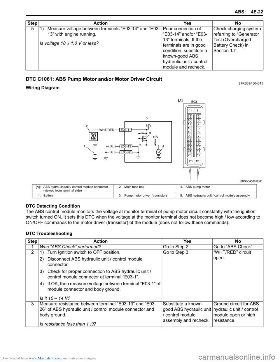
Wiring Diagram
DTC Detecting Condition
The ABS control module monitors the voltage at monitor terminal of pump motor circuit constantly with the ignition
switch turned ON. It sets this DTC when the voltage at the monitor terminal does not become high / low according to
ON/OFF commands to the motor driver (transistor) of the module (does not follow these commands).
DTC Troubleshooting 5 1) Measure voltage between terminals “E03-14” and “E03-
13” with engine running.
Is voltage 18
± 1.0 V or less? Poor connection of
“E03-14” and/or “E03-
13” terminals. If the
terminals are in good
condition, substitute a
known-good ABS
hydraulic unit / control
module and recheck.Check charging system
referring to “Generator
Test (Overcharged
Battery Check) in
Section 1J”.
Step Action Yes No
WHT/RED
1 2
5
BLK
BLK
E03-13
E03-26
[A]
E03
15
16
17
18
19
20
21
22
23
24
25 2
3
4
5
6
7
8
9
10
11
12
1
13
14
26
M
3
4E03-1
12V
12V
I6RS0C450012-01
[A]: ABS hydraulic unit / control module connector (viewed from terminal side) 2. Main fuse box 4. ABS pump motor
1. Battery 3. Pump motor driver (transistor) 5. ABS hydraulic unit / control module assembly
StepAction YesNo
1 Was “ABS Check” performed? Go to Step 2.Go to “ABS Check”.
2 1) Turn Ignition switch to OFF position.
2) Disconnect ABS hydraulic unit / control module connector.
3) Check for proper connection to ABS hydraulic unit / control module connector at terminal “E03-1”.
4) If OK, then measure voltage between terminal “E03-1” of module connector and body ground.
Is it 10 – 14 V? Go to Step 3.
“WHT/RED” circuit
open.
3 Measure resistance between terminal “E03-13” and “E03- 26” of ABS hydraulic unit / co ntrol module connector and
body ground.
Is resistance less than 1
Ω? Substitute a known-
good ABS hydraulic unit
/ control module
assembly and recheck.
Ground circuit for ABS
hydraulic unit / control
module open or high
resistance.
Page 562 of 1496
Downloaded from www.Manualslib.com manuals search engine 4E-23 ABS:
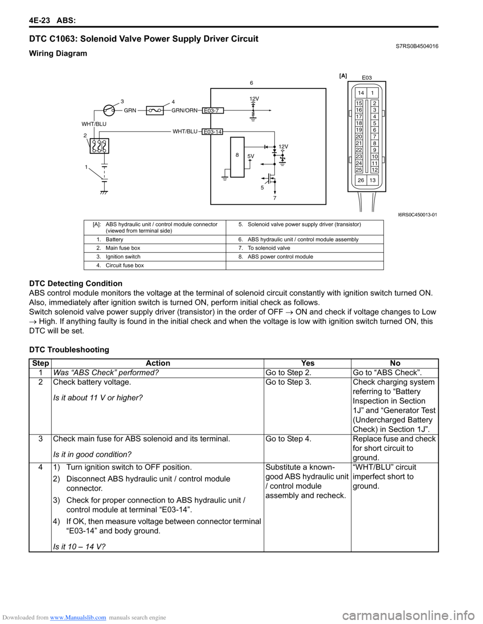
DTC C1063: Solenoid Valve Power Supply Driver CircuitS7RS0B4504016
Wiring Diagram
DTC Detecting Condition
ABS control module monitors the voltage at the terminal of solenoid circuit constantly with ignition switch turned ON.
Also, immediately after ignition switch is turned ON, perform initial check as follows.
Switch solenoid valve power supply driv er (transistor) in the order of OFF → ON and check if voltage changes to Low
→ High. If anything faulty is found in the initial check and when the voltage is low with ignition switch turned ON, this
DTC will be set.
DTC Troubleshooting
[A] E03
15
16
17
18
19
20
21
22
23
24
25 2
3
4
5
6
7
8
9
10
11
12
1
13
14
266
WHT/BLU
12V
5E03-14
5V
12V
8
GRN/ORNE03-7
WHT/BLU
GRN
1
2 3
4
7
I6RS0C450013-01
[A]: ABS hydraulic unit / control module connector
(viewed from terminal side) 5. Solenoid valve power supp
ly driver (transistor)
1. Battery 6. ABS hydraulic unit / control module assembly
2. Main fuse box 7. To solenoid valve
3. Ignition switch 8. ABS power control module
4. Circuit fuse box
Step Action YesNo
1 Was “ABS Check” performed? Go to Step 2.Go to “ABS Check”.
2 Check battery voltage.
Is it about 11 V or higher? Go to Step 3.
Check charging system
referring to “Battery
Inspection in Section
1J” and “Generator Test
(Undercharged Battery
Check) in Section 1J”.
3 Check main fuse for ABS solenoid and its terminal.
Is it in good condition? Go to Step 4.
Replace fuse and check
for short circuit to
ground.
4 1) Turn ignition switch to OFF position.
2) Disconnect ABS hydraulic unit / control module connector.
3) Check for proper connection to ABS hydraulic unit / control module at terminal “E03-14”.
4) If OK, then measure voltage between connector terminal “E03-14” and body ground.
Is it 10 – 14 V? Substitute a known-
good ABS hydraulic unit
/ control module
assembly and recheck.
“WHT/BLU” circuit
imperfect short to
ground.
Page 615 of 1496
Downloaded from www.Manualslib.com manuals search engine Electronic Stability Program: 4F-41
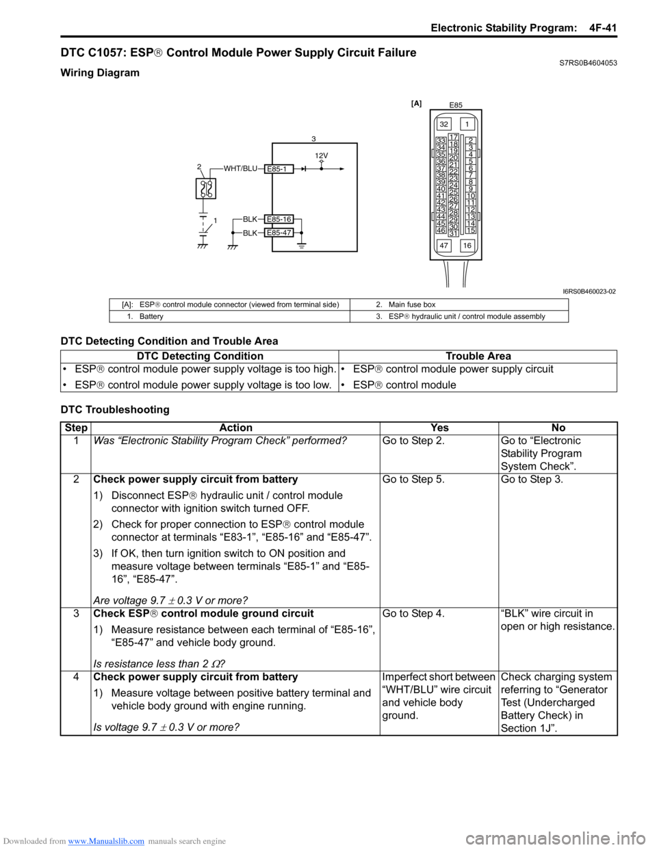
DTC C1057: ESP® Control Module Power Supply Circuit FailureS7RS0B4604053
Wiring Diagram
DTC Detecting Condition and Trouble Area
DTC Troubleshooting
[A]
E85
161
15
2
3
4
5
6
7
8
9
10
11
12
13
14
17
18
19
20
21
22
23
24
25
26
27
28
29
30
31
3233
34
35
36
37
38
39
40
41
42
43
44
45
46
47
WHT/BLU
1
2
3
12V
E85-1
BLKE85-16
E85-47BLK
I6RS0B460023-02
[A]: ESP
® control module connector (viewed from terminal side) 2. Main fuse box
1. Battery 3. ESP ® hydraulic unit / control module assembly
DTC Detecting Condition Trouble Area
• ESP ® control module power supply voltage is too high.
• ESP ® control module power supply voltage is too low. • ESP
® control module power supply circuit
• ESP ® control module
Step Action YesNo
1 Was “Electronic Stability Pr ogram Check” performed? Go to Step 2.Go to “Electronic
Stability Program
System Check”.
2 Check power supply circuit from battery
1) Disconnect ESP ® hydraulic unit / control module
connector with ignition switch turned OFF.
2) Check for proper connection to ESP ® control module
connector at terminals “E83-1”, “E85-16” and “E85-47”.
3) If OK, then turn ignition switch to ON position and measure voltage between terminals “E85-1” and “E85-
16”, “E85-47”.
Are voltage 9.7
± 0.3 V or more? Go to Step 5. Go to Step 3.
3 Check ESP ® control module ground circuit
1) Measure resistance between each terminal of “E85-16”, “E85-47” and vehicle body ground.
Is resistance less than 2
Ω? Go to Step 4. “BLK” wire circuit in
open or high resistance.
4 Check power supply circuit from battery
1) Measure voltage between positive battery terminal and
vehicle body ground with engine running.
Is voltage 9.7
± 0.3 V or more? Imperfect short between
“WHT/BLU” wire circuit
and vehicle body
ground.
Check charging system
referring to “Generator
Test (Undercharged
Battery Check) in
Section 1J”.