Warning light SUZUKI SWIFT 2006 2.G Service Service Manual
[x] Cancel search | Manufacturer: SUZUKI, Model Year: 2006, Model line: SWIFT, Model: SUZUKI SWIFT 2006 2.GPages: 1496, PDF Size: 34.44 MB
Page 887 of 1496
Downloaded from www.Manualslib.com manuals search engine Power Assisted Steering System: 6C-5
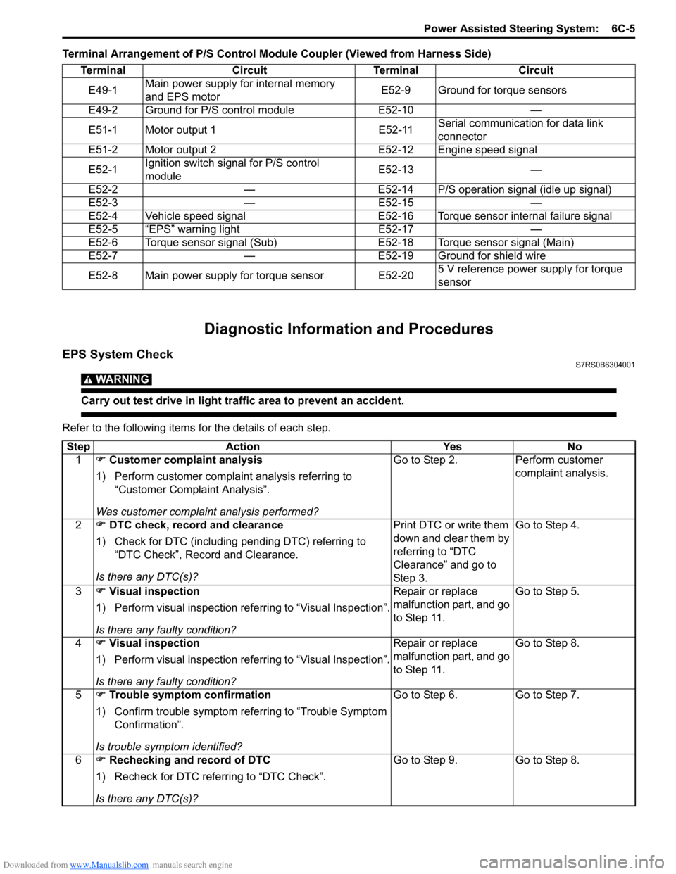
Terminal Arrangement of P/S Control Module Coupler (Viewed from Harness Side)
Diagnostic Information and Procedures
EPS System CheckS7RS0B6304001
WARNING!
Carry out test drive in light traffic area to prevent an accident.
Refer to the following items for the details of each step.Terminal Circuit Terminal Circuit
E49-1 Main power supply for internal memory
and EPS motor E52-9 Ground for torque sensors
E49-2 Ground for P/S control module E52-10 —
E51-1 Motor output 1 E52-11 Serial communication for data link
connector
E51-2 Motor output 2 E52-12 Engine speed signal
E52-1 Ignition switch signal for P/S control
module E52-13 —
E52-2 — E52-14 P/S operation signal (idle up signal)
E52-3 — E52-15 —
E52-4 Vehicle speed signal E52-16 Torque sensor internal failure signal
E52-5 “EPS” warning light E52-17 —
E52-6 Torque sensor signal (Sub) E52-18 Torque sensor signal (Main)
E52-7 — E52-19 Ground for shield wire
E52-8 Main power supply for torque sensor E52-20 5 V reference power supply for torque
sensor
Step
Action YesNo
1 �) Customer complaint analysis
1) Perform customer complaint analysis referring to “Customer Complaint Analysis”.
Was customer complaint analysis performed? Go to Step 2.
Perform customer
complaint analysis.
2 �) DTC check, record and clearance
1) Check for DTC (including pending DTC) referring to “DTC Check”, Record and Clearance.
Is there any DTC(s)? Print DTC or write them
down and clear them by
referring to “DTC
Clearance” and go to
St ep 3 .Go to Step 4.
3 �) Visual inspection
1) Perform visual inspection referring to “Visual Inspection”.
Is there any faulty condition? Repair or replace
malfunction part, and go
to Step 11.
Go to Step 5.
4 �) Visual inspection
1) Perform visual inspection referring to “Visual Inspection”.
Is there any faulty condition? Repair or replace
malfunction part, and go
to Step 11.
Go to Step 8.
5 �) Trouble symptom confirmation
1) Confirm trouble symptom referring to “Trouble Symptom Confirmation”.
Is trouble symptom identified? Go to Step 6.
Go to Step 7.
6 �) Rechecking and record of DTC
1) Recheck for DTC referring to “DTC Check”.
Is there any DTC(s)? Go to Step 9.
Go to Step 8.
Page 888 of 1496
Downloaded from www.Manualslib.com manuals search engine 6C-6 Power Assisted Steering System:
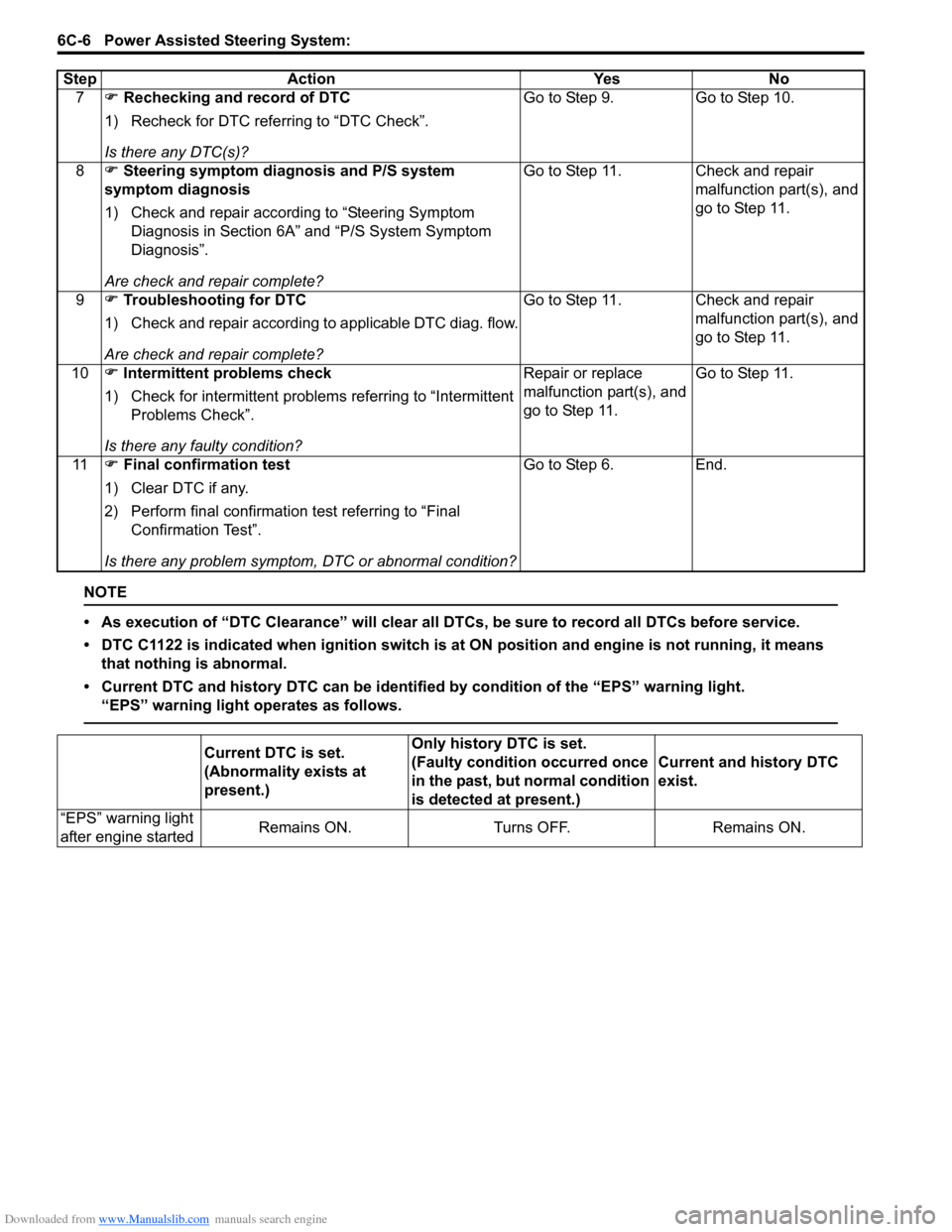
NOTE
• As execution of “DTC Clearance” will clear all DTCs, be sure to record all DTCs before service.
• DTC C1122 is indicated when ignition switch is at ON position and engine is not running, it means
that nothing is abnormal.
• Current DTC and history DTC ca n be identified by condition of the “EPS” warning light.
“EPS” warning light operates as follows.
7 �) Rechecking and record of DTC
1) Recheck for DTC referring to “DTC Check”.
Is there any DTC(s)? Go to Step 9. Go to Step 10.
8 �) Steering symptom diagnosis and P/S system
symptom diagnosis
1) Check and repair according to “Steering Symptom Diagnosis in Section 6A” and “P/S System Symptom
Diagnosis”.
Are check and repair complete? Go to Step 11. Check and repair
malfunction part(s), and
go to Step 11.
9 �) Troubleshooting for DTC
1) Check and repair according to applicable DTC diag. flow.
Are check and repair complete? Go to Step 11. Check and repair
malfunction part(s), and
go to Step 11.
10 �) Intermittent problems check
1) Check for intermittent problems referring to “Intermittent Problems Check”.
Is there any faulty condition? Repair or replace
malfunction part(s), and
go to Step 11.
Go to Step 11.
11 �) Final confirmation test
1) Clear DTC if any.
2) Perform final confirmation test referring to “Final Confirmation Test”.
Is there any problem symptom, DTC or abnormal condition? Go to Step 6. End.
Step Action Yes No
Current DTC is set.
(Abnormality exists at
present.)
Only history DTC is set.
(Faulty condition occurred once
in the past, but normal condition
is detected at present.)
Current and history DTC
exist.
“EPS” warning light
after engine started Remains ON. Turns OFF. Remains ON.
Page 890 of 1496
Downloaded from www.Manualslib.com manuals search engine 6C-8 Power Assisted Steering System:
Step 2: DTC Check, Record and Clearance
First, check DTC, referring to “DTC Check”. If DTC is
indicated, print it or write them down and then clear them
by referring to “DTC Clearance”. DTC indicates
malfunction that occurred in the system but does not
indicate whether it exists now or it occurred in the past
and the normal condition has been restored now. To
check which case applies, check the symptom in
question according to Step 5 and recheck DTC
according to Step 6 and 7.
Attempt to diagnose a trouble based on DTC in this step
only or failure to clear the DTC in this step will lead to
incorrect diagnosis, trouble diagnosis of a normal circuit
or difficulty in troubleshooting.
Step 3 and 4: Visual Inspection
As a preliminary step, be sure to perform visual check of
the items that support proper function of the P/S system
referring to “Visual Inspection”.
Step 5: Trouble Symptom Confirmation
Based on information obtained in “Step 1: Customer
Complaint Analysis: ” and “S tep 2: DTC Check, Record
and Clearance: ”, confirm trouble symptoms. Also,
reconfirm trouble symptom by performing test drive and
turning steering wheel fully to right and left at stopped
vehicle.
Step 6 and 7: Rechecking and Record of DTC
Refer to “DTC Check” for checking procedure.
Step 8: Steering Symptom Diagnosis and P/S
System Symptom Diagnosis
Perform basic steering system check according to
“Steering Symptom Diagnosis in Section 6A” first. When
the end of the flow has been reached, check the parts of
the system suspected as a possible cause referring to
“P/S System Symptom Diagnosis” and based on
symptoms appearing on the vehicle (symptoms obtained
through steps of customer complaint analysis, trouble
symptom confirmation and/or basic P/S system check)
and repair or replace faulty parts, if any.
Step 9: Troubleshooting for DTC (See each DTC
Diag. Flow)
Based on the DTC indicated in Step 6 or 7 and referring
to the applicable DTC diag. flow, locate the cause of the
trouble, namely in a sensor, switch, wire harness,
connector, actuator, P/S control module or other part and
repair or replace faulty parts.
Step 10: Intermittent Problems Check
Check parts where an intermittent trouble is easy to
occur (e.g., wire harness, connector, etc.), referring to
“Intermittent and Poor Connection Inspection in Section
00” and related circuit of DTC recorded in Step 2. Step 11: Final Confirmation Test
Confirm that the problem symptom has gone and the P/
S system is free from any abnormal conditions. If what
has been repaired is related to the DTC, clear the DTC
once, perform DTC confirmation procedure and confirm
that no DTC is indicated.
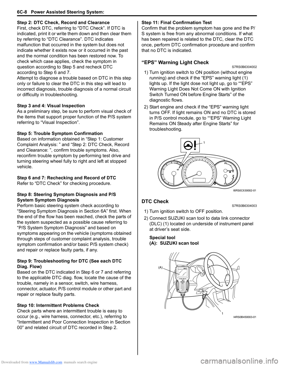
“EPS” Warning Light CheckS7RS0B6304002
1) Turn ignition switch to ON position (without engine
running) and chec k if the “EPS” warning light (1)
lights up. If the light dose not light up, go to ““EPS”
Warning Light Does Not Come ON with Ignition
Switch Turned ON before Engine Starts” of the
diagnostic flows.
2) Start engine and check if the “EPS” warning light turns OFF. If light remains ON and no DTC is stored
in P/S control module, go to ““EPS” Warning Light
Remains ON Steady after Engine Starts” for
troubleshooting.
DTC CheckS7RS0B6304003
1) Turn ignition switch to OFF position.
2) Connect SUZUKI scan tool to data link connector (DLC) (1) located on underside of instrument panel
at driver’s seat side.
Special tool
(A): SUZUKI scan tool
1
I6RS0C630002-01
(A)
1
I4RS0B450003-01
Page 895 of 1496
Downloaded from www.Manualslib.com manuals search engine Power Assisted Steering System: 6C-13
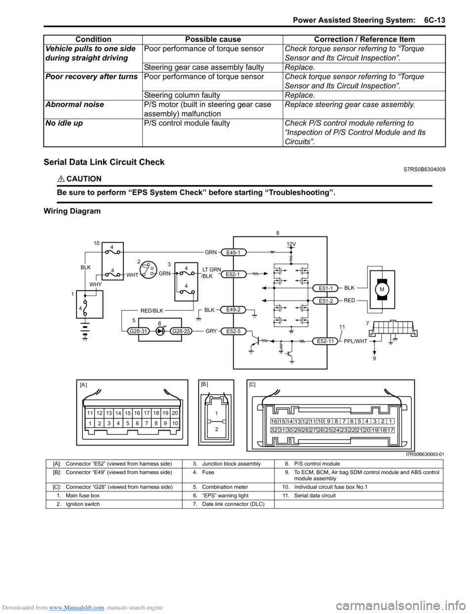
Serial Data Link Circuit CheckS7RS0B6304009
CAUTION!
Be sure to perform “EPS System Check” before starting “Troubleshooting”.
Wiring DiagramVehicle pulls to one side
during straight driving
Poor performance of torque sensor
Check torque sensor referring to “Torque
Sensor and Its Circuit Inspection”.
Steering gear case assembly faulty Replace.
Poor recovery after turns Poor performance of torque sensor Check torque sensor referring to “Torque
Sensor and Its Circuit Inspection”.
Steering column faulty Replace.
Abnormal noise P/S motor (built in steering gear case
assembly) malfunction Replace steering gear case assembly.
No idle up P/S control module faulty Check P/S control module referring to
“Inspection of P/S Control Module and Its
Circuits”.
Condition Possible cause Correction / Reference Item
MBLK
RED
E52-11 E51-1
E51-2PPL/WHT
[A ]
12
3
4 5 67
89
11
10
12 13
141516
17 18 19 2010 9 8 7654 3 21
16 15 14 13 12 11
26 25 24 2322 21 20 19 18 17
32 31 30 29 28 27
[C]
8
79
12V
[B ]
11
12
GRY
LT GRN
/BLK
E52-1
E52-5
E49-1
GRNGRNWHTBLK
WHY
G28-25G28-31
RED/BLK
10
3
4
4
5 6
4
4
1 2
4
E49-2BLK
I7RS0B630003-01
[A]: Connector “E52” (viewed from harness side) 3. Junction block assembly 8. P/S control module
[B]: Connector “E49” (viewed from harness side) 4. Fuse 9. T o ECM, BCM, Air bag SDM control module and ABS control
module assembly
[C]: Connector “G28” (viewed from harness side) 5. Comb ination meter 10. Individual circuit fuse box No.1
1. Main fuse box 6. “EPS” warning light 11. Serial data circuit
2. Ignition switch 7. Date link connector (DLC)
Page 897 of 1496
Downloaded from www.Manualslib.com manuals search engine Power Assisted Steering System: 6C-15
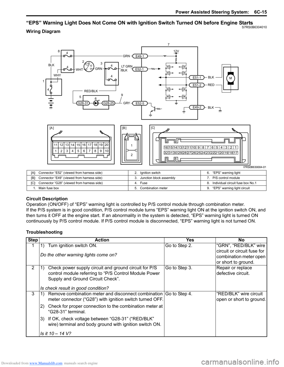
“EPS” Warning Light Does Not Come ON with Ignition Switch Turned ON before Engine StartsS7RS0B6304010
Wiring Diagram
Circuit Description
Operation (ON/OFF) of “EPS” warning light is controlled by P/S control module through combination meter.
If the P/S system is in good condition, P/S control module turns “ EPS” warning light ON at the ignition switch ON, and
then turns it OFF at the engine start. If an abnormality in the system is detected, “EPS” warning light is turned ON
continuously by P/S control module. If P/S control module is disconnected, “EPS” warning light is not turned ON.
Troubleshooting
MBLK
REDE51-1
E51-2
[A ]
12 3
4 5 67
89
11
10
12 13
141516
17 18 19 2010 9 8 7654 3 21
16 15 14 13 12 11
26 25 24 2322 21 20 19 18 17
32 31 30 29 28 27
[C]
7
12V
E49-2BLK
[B ]
1 2
GRY
LT GRN
/BLK
E52-1
E52-5
E49-1
GRNGRNWHTBLK
WHY
G28-25G28-31
RED/BLK
8
3
4
4
5 6
4
4
1 2
4
9
I7RS0B630004-01
[A]: Connector “E52” (viewed from harness side) 2. Ignition switch6. “EPS” warning light
[B]: Connector “E49” (viewed from harness side) 3. Junction block assembly7. P/S control module
[C]: Connector “G28” (viewed from harness si de)4. Fuse 8. Individual circuit fuse box No.1
1. Main fuse box 5. Combination meter9. “EPS” warning light circuit
StepAction YesNo
1 1) Turn ignition switch ON.
Do the other warning lights come on? Go to Step 2.
“GRN”, “RED/BLK” wire
circuit or circuit fuse for
combination meter open
or short to ground.
2 1) Check power supply circuit and ground circuit for P/S control module referring to “P/S Control Module Power
Supply and Ground Circuit Check”.
Is check result in good condition? Go to Step 3.
Repair or replace
defective circuit.
3 1) Remove combination meter and disconnect combination meter connector (“G28”) with ignition switch turned OFF.
2) Check for proper connection to the combination meter at “G28-31” terminal.
3) If OK, check voltage between “G28-31” (“RED/BLK” wire) terminal and body ground with ignition switch ON.
Is it 10 – 14 V? Go to Step 4.
“RED/BLK” wire circuit
open or short to ground.
Page 898 of 1496
Downloaded from www.Manualslib.com manuals search engine 6C-16 Power Assisted Steering System:
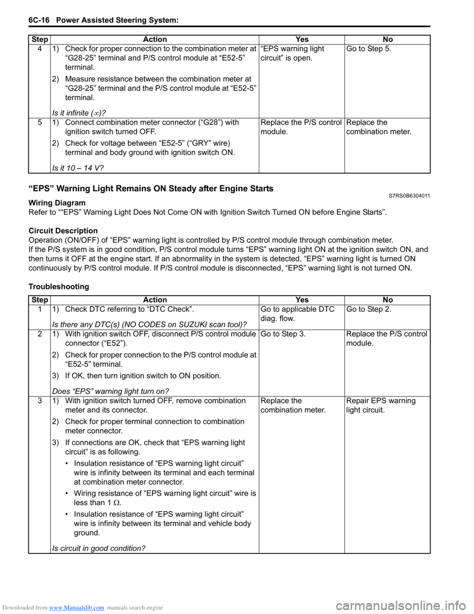
“EPS” Warning Light Remains ON Steady after Engine StartsS7RS0B6304011
Wiring Diagram
Refer to ““EPS” Warning Light Does Not Come ON with Ignition Switch Turned ON before Engine Starts”.
Circuit Description
Operation (ON/OFF) of “EPS” warning light is controlled by P/S c ontrol module through combination meter.
If the P/S system is in good condition, P/S control module tu rns “EPS” warning light ON at the ignition switch ON, and
then turns it OFF at the engine start. If an abnormality in the system is detected, “EPS” warning light is turned ON
continuously by P/S control module. If P/S control module is disconnected, “EPS” warning light is not turned ON.
Troubleshooting 4 1) Check for proper connection to the combination meter at
“G28-25” terminal and P/S control module at “E52-5”
terminal.
2) Measure resistance between the combination meter at “G28-25” terminal and the P/S control module at “E52-5”
terminal.
Is it infinite (
∞)? “EPS warning light
circuit” is open.
Go to Step 5.
5 1) Connect combination meter connector (“G28”) with ignition switch turned OFF.
2) Check for voltage between “E52-5” (“GRY” wire) terminal and body ground with ignition switch ON.
Is it 10 – 14 V? Replace the P/S control
module.
Replace the
combination meter.
Step
Action YesNo
Step Action YesNo
1 1) Check DTC referring to “DTC Check”.
Is there any DTC(s) (NO CODES on SUZUKI scan tool)? Go to applicable DTC
diag. flow.
Go to Step 2.
2 1) With ignition switch OFF, disconnect P/S control module connector (“E52”).
2) Check for proper connection to the P/S control module at “E52-5” terminal.
3) If OK, then turn ignition switch to ON position.
Does “EPS” warning light turn on? Go to Step 3.
Replace the P/S control
module.
3 1) With ignition switch turned OFF, remove combination meter and its connector.
2) Check for proper terminal connection to combination meter connector.
3) If connections are OK, ch eck that “EPS warning light
circuit” is as following.
• Insulation resistance of “EPS warning light circuit” wire is infinity between its terminal and each terminal
at combination meter connector.
• Wiring resistance of “EPS wa rning light circuit” wire is
less than 1 Ω.
• Insulation resistance of “EPS warning light circuit” wire is infinity between its terminal and vehicle body
ground.
Is circuit in good condition? Replace the
combination meter.
Repair EPS warning
light circuit.
Page 918 of 1496
Downloaded from www.Manualslib.com manuals search engine 6C-36 Power Assisted Steering System:
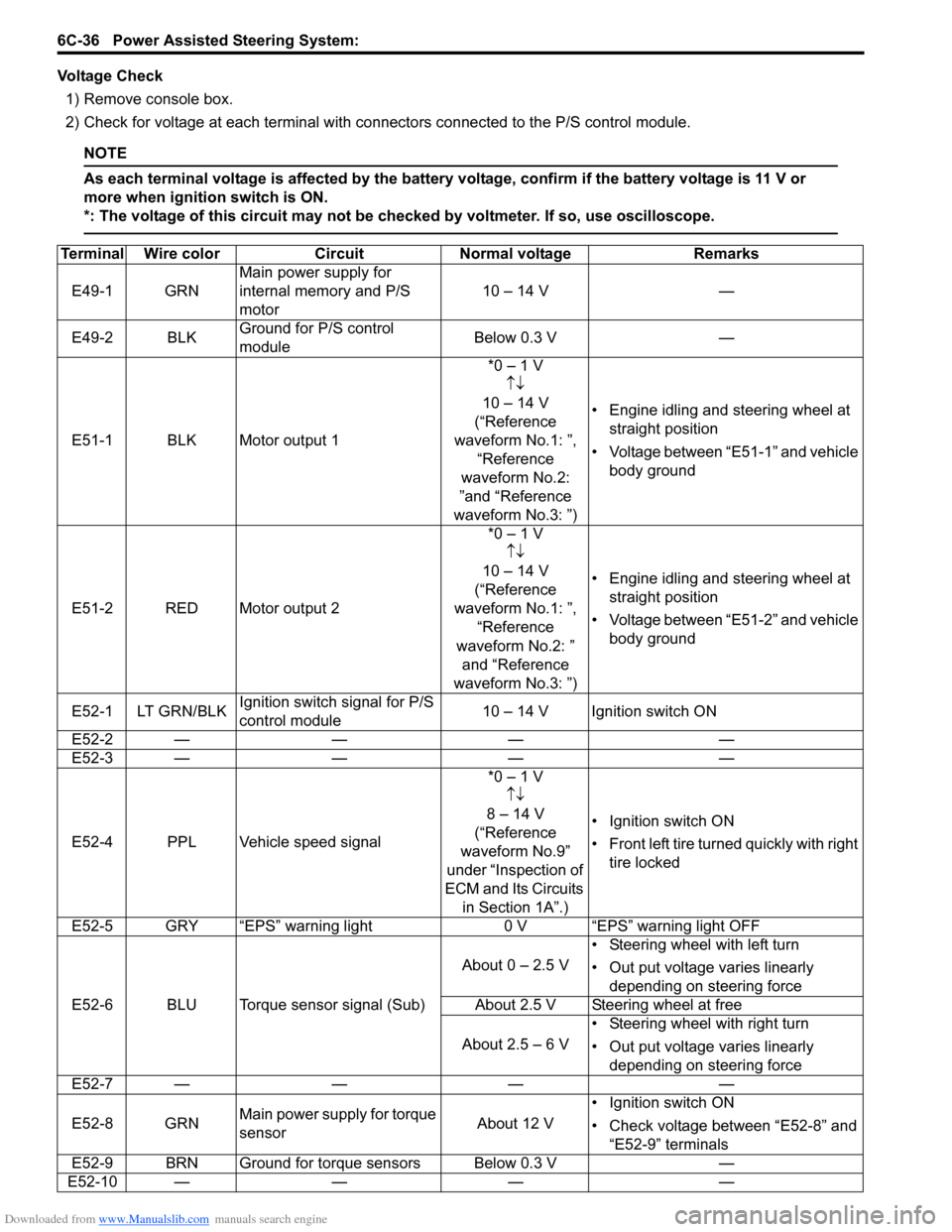
Voltage Check1) Remove console box.
2) Check for voltage at each terminal with co nnectors connected to the P/S control module.
NOTE
As each terminal voltage is affected by the battery voltage, confirm if the battery voltage is 11 V or
more when ignition switch is ON.
*: The voltage of this circuit may not be checked by voltmeter. If so, use oscilloscope.
Terminal Wire colorCircuit Normal voltage Remarks
E49-1 GRN Main power supply for
internal memory and P/S
motor 10 – 14 V
—
E49-2 BLK Ground for P/S control
module Below 0.3 V
—
E51-1 BLK Motor output 1 *0 – 1 V
↑↓
10 – 14 V
(“Reference
waveform No.1: ”, “Reference
waveform No.2:
”and “Reference
waveform No.3: ”) • Engine idling and steering wheel at
straight position
• Voltage between “E51-1” and vehicle body ground
E51-2 RED Motor output 2 *0 – 1 V
↑↓
10 – 14 V
(“Reference
waveform No.1: ”, “Reference
waveform No.2: ” and “Reference
waveform No.3: ”) • Engine idling and steering wheel at
straight position
• Voltage between “E51-2” and vehicle body ground
E52-1 LT GRN/BLK Ignition switch signal for P/S
control module 10 – 14 V Ignition switch ON
E52-2 — —— —
E52-3 — —— —
E52-4 PPL Vehicle speed signal *0 – 1 V
↑↓
8 – 14 V
(“Reference
waveform No.9”
under “Inspection of
ECM and Its Circuits in Section 1A”.) • Ignition switch ON
•Front left tire tu
rned quickly with right
tire locked
E52-5 GRY “EPS” warning light 0 V “EPS” warning light OFF
E52-6 BLU Torque sensor signal (Sub) About 0 – 2.5 V
• Steering wheel with left turn
• Out put voltage varies linearly
depending on steering force
About 2.5 V Steering wheel at free
About 2.5 – 6 V • Steering wheel with right turn
• Out put voltage varies linearly
depending on steering force
E52-7 — —— —
E52-8 GRN Main power supply for torque
sensor About 12 V• Ignition switch ON
• Check voltage between “E52-8” and
“E52-9” terminals
E52-9 BRN Ground for torque sensors Below 0.3 V —
E52-10 — —— —
Page 964 of 1496
Downloaded from www.Manualslib.com manuals search engine 7B-16 Air Conditioning System: Manual Type
Repair Instructions
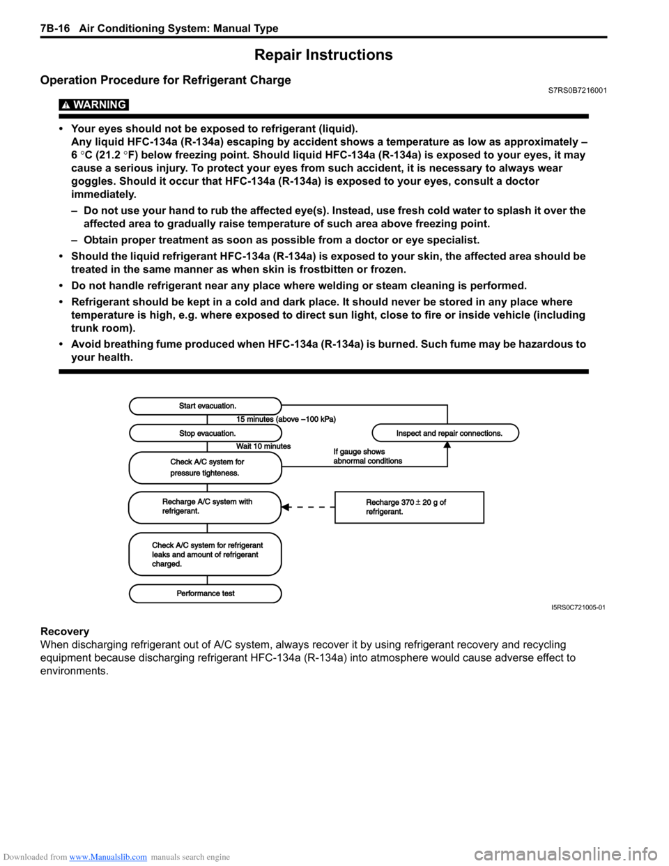
Operation Procedure for Refrigerant ChargeS7RS0B7216001
WARNING!
• Your eyes should not be exposed to refrigerant (liquid).Any liquid HFC-134a (R-134a) escaping by accident shows a temperature as low as approximately –
6 °C (21.2 ° F) below freezing point. Should liquid HFC-134a (R-134a) is exposed to your eyes, it may
cause a serious injury. To protect your eyes from such accident, it is necessary to always wear
goggles. Should it occur that HFC-134a (R-134a) is exposed to your eyes, consult a doctor
immediately.
– Do not use your hand to rub the affected eye(s). Instead, use fresh cold water to splash it over the affected area to gradually raise temperature of such area above freezing point.
– Obtain proper treatment as soon as possible from a doctor or eye specialist.
• Should the liquid refrigerant HFC-134a (R-134a) is exposed to your skin, the affected area should be treated in the same manner as when skin is frostbitten or frozen.
• Do not handle refrigerant near any place where welding or steam cleaning is performed.
• Refrigerant should be kept in a cold and dark pl ace. It should never be stored in any place where
temperature is high, e.g. where exposed to direct su n light, close to fire or inside vehicle (including
trunk room).
• Avoid breathing fume produced when HFC-134a (R-134a) is burned. Such fume may be hazardous to your health.
Recovery
When discharging refrigerant out of A/C system, always recover it by using refrigerant recovery and recycling
equipment because discharging refrigerant HFC-134a (R-1 34a) into atmosphere would cause adverse effect to
environments.
Start evacuation.Start evacuation.
Stop evacuation.Stop evacuation.
Wait 10 minutesWait 10 minutes
Check A/C system forCheck A/C system for
pressure tighteness.pressure tighteness.
Recharge A/C system withRecharge A/C system withrefrigerant.refrigerant.
Check A/C system for refrigerantCheck A/C system for refrigerantleaks and amount of refrigerantleaks and amount of refrigerantcharged.charged.
Performance testPerformance test
Inspect and repair connections.Inspect and repair connections.
If gauge showsIf gauge showsabnormal conditionsabnormal conditions
Recharge 370 20 g ofRecharge 370 20 g ofrefrigerant.refrigerant.
I5RS0C721005-01
Page 1033 of 1496
Downloaded from www.Manualslib.com manuals search engine Seat Belts: 8A-2
Seat Belt with ELR
The seat belt with emergency locking retractor (ELR) is
designed so that it locks immediately (to prevent the
webbing from being pulled out of the retractor any
further) when any of the following items is detected as
exceeding each set value;
• Speed at which the webbing is pulled out of the retractor.
• Acceleration or deceleration of the vehicle speed.
• Inclination.
Seat Belt with A-ELR
The automatic and emergency locking retractor (A-ELR)
works as an Emergency Locking Retractor (ELR) till its
webbing is pulled all the way out and then on as an
Automatic Locking Retractor (ALR ) till it is retracted fully.
ALR: Automatically locks when the webbing is pulled out
from the retractor and allowed to retract even a little.
Then the webbing can not be pulled out any further,
unless it is wound all the way back into the retractor,
which releases the lock and allows the webbing to be
pulled out.
Seat Belt with ELR and Pretensioner
The seat belt with ELR and a pretensioner has a
pretensioner mechanism whic h operates in linkage with
the air bag in addition to the described ELR.
The pretensioner is incorporated in retractor assembly
and controlled by SDM as one of air bag system
components. It will be activated at the same time as the
driver and passenger air bag module when an impact at
the front of vehicle exceeds the specified value.
When servicing seat belt (retractor assembly) with
pretensioner, be sure to observe all WARNINGS and
CAUTIONS and “Precautions on Service and Diagnosis
of Air Bag System in Section 8B”. CAUTION!
Do not reuse the seat belt pretensioner
(retractor assembly) that has activated.
Replace it with a new seat belt assembly and
buckle together as a set. For checking
procedure of its activation, refer to “Repair
and Inspection Required after Accident in
Section 8B”.
Seat Belt Remainder
When driver’s seat belt is unfastened (under the
following conditions), seat belt reminder light and
warning buzzer inform that driver’s seat belt is
unfastened. Seat belt reminder light located in
combination meter and warning buzzer located inside
BCM operate as follows:
• Seat belt reminder light comes on when driver’s seat belt is unfastened while igni tion key switch is at ON
position.
• If vehicle speed exceeds 15 km/h with seat belt unfastened, warning buzzer operates for
approximately 95 seconds and seat belt reminder light
flashes synchronously with buzzer. When warning
buzzer stops operating, seat belt reminder light is
turned on.
• If driver’s seat belt state is changed from “fastened” to “unfastened” while vehicle speed is above 15 km/h,
warning buzzer operates for approximately 95
seconds and seat belt reminder light flashes
synchronously with buzzer. When warning buzzer
stops operating, seat belt reminder light is turned on.
Diagnostic Information and Procedures
Repair and Inspection Required after AccidentS7RS0B8104001
After an accident, whether the seat belt pretensioner has been activated or not, be sure to perform checks and repairs
described on “Repair and Inspection Required after Accident in Section 8B”.
Page 1045 of 1496
![SUZUKI SWIFT 2006 2.G Service Service Manual Downloaded from www.Manualslib.com manuals search engine Air Bag System: 8B-7
Schematic and Routing Diagram
Air Bag System Wiring Circuit DiagramS7RS0B8202001
[A]
[B]“E13” “E44”, “G04� SUZUKI SWIFT 2006 2.G Service Service Manual Downloaded from www.Manualslib.com manuals search engine Air Bag System: 8B-7
Schematic and Routing Diagram
Air Bag System Wiring Circuit DiagramS7RS0B8202001
[A]
[B]“E13” “E44”, “G04�](/img/20/7607/w960_7607-1044.png)
Downloaded from www.Manualslib.com manuals search engine Air Bag System: 8B-7
Schematic and Routing Diagram
Air Bag System Wiring Circuit DiagramS7RS0B8202001
[A]
[B]“E13” “E44”, “G04” “G35” and "L03" \
"L41"
1
2 GRN/RED
GRN GRN/RED
GRN
BLU/RED YEL/RED BLU/RED
YEL/RED
GRN/ORN GRN/YEL
RED
13
PPL/WHT
9 7
8
5
6
10 “L10”
“L11”
“L04”
“G35” “G34”
“G33”
“G28”
“G32”
“L35”
L29-2
L29-27
L29-32 L29-5
L29-6 L29-4
L29-3
L29-8
L29-7
IG
ST
YEL L29-37ADS
WHT/RED
LT GRN/BLK L29-46
L29-47 SD+
SD-
11
WHT/GRN LT GRN
BLK L29-45
L29-44 WL
L29-28
E1 DP-
DP+ P- P+ D- D+
“G10”
“G04”“L29”
18
BLU/ORN
BLU/YEL “L36”
L29-9
L29-10
PP-
PP+
19 17
GRY/RED
GRY
L29-12
L29-11
DS- DS+ “L25”
20
BRN/WHT
BRN
L29-13
L29-14
PS- PS+ “L30”
21
YEL/GRN
YEL/BLU
L29-20
L29-19
DC- DC+ “L18”
22
BLK/YEL
BRN/YEL
L29-21
L29-22
PC- PC+ “L41”
2316
15
14
“L29”
SP+
SP-
“G26”“L32”
“L03”“E44”“E13”
12
ORN
PNK/BLK
GRY/RED
GRY L29-50
L29-51 FD+
FD-
3 4
YEL/BLK
YEL/BLK
GRN RED/BLK
I7RS0A820002-03
[A]: Shorting bar
8. BCM 17. Passenger air bag (inflator) module
[B]: Connector 9. To data link connector (DLC)18. Driver seat belt pretensioner
1. To battery 10. Driver side-sensor (if equipped)19. Passenger seat belt pretensioner
2. Ignition switch 11. Passenger side-sensor (if equipped) 20. Driver side-air bag (inflator) module (if equipped)
3. “AIR BAG” warning light 12. Forward-sensor 21. Passenger side-air bag (inflator) module (if equipped)
4. Light driver 13. Ground for air bag system 22. Driver side curtain-air bag (inflator) module (if equipped)
5. “METER” fuse 14. SDM 23. Passenger side curtain-air bag (inflator) module (if equipped)
6. “A/BAG” fuse 15. Contact coil
7. Junction block assembly 16. Driver air bag (inflator) module