Speed meter SUZUKI SWIFT 2006 2.G Service Repair Manual
[x] Cancel search | Manufacturer: SUZUKI, Model Year: 2006, Model line: SWIFT, Model: SUZUKI SWIFT 2006 2.GPages: 1496, PDF Size: 34.44 MB
Page 1299 of 1496
Downloaded from www.Manualslib.com manuals search engine Instrumentation / Driver Info. / Horn: 9C-4
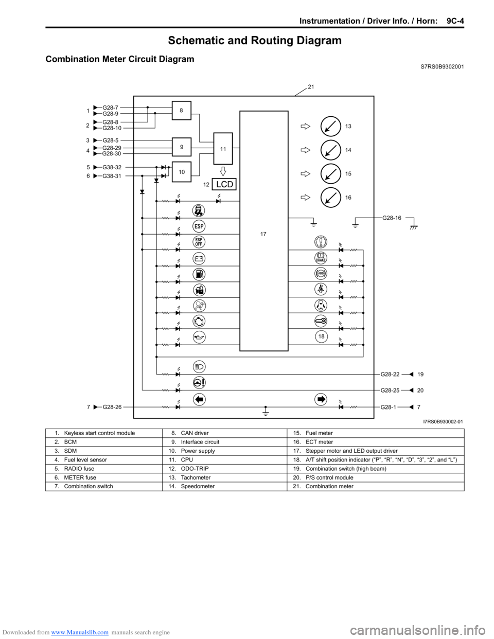
Schematic and Routing Diagram
Combination Meter Circuit DiagramS7RS0B9302001
16
15
14
13
G28-5
5
6
3
G28-26
7
G28-2219
G28-2520
G28-17
12
10 11
21
9
17
G28-304G28-29
18
G28-16
G28-9
G28-10G28-8 G28-7
1
2 8
G38-31
G38-32
I7RS0B930002-01
1. Keyless start control module
8. CAN driver 15. Fuel meter
2. BCM 9. Interface circuit 16. ECT meter
3. SDM 10. Power supply 17. Stepper motor and LED output driver
4. Fuel level sensor 11. CPU 18. A/T shift position indicator (“P”, “R”, “N”, “D”, “3”, “2”, and “L”)
5. RADIO fuse 12. ODO-TRIP 19. Combination switch (high beam)
6. METER fuse 13. Tachometer 20. P/S control module
7. Combination switch 14. Speedometer 21. Combination meter
Page 1301 of 1496
Downloaded from www.Manualslib.com manuals search engine Instrumentation / Driver Info. / Horn: 9C-6
Component Location
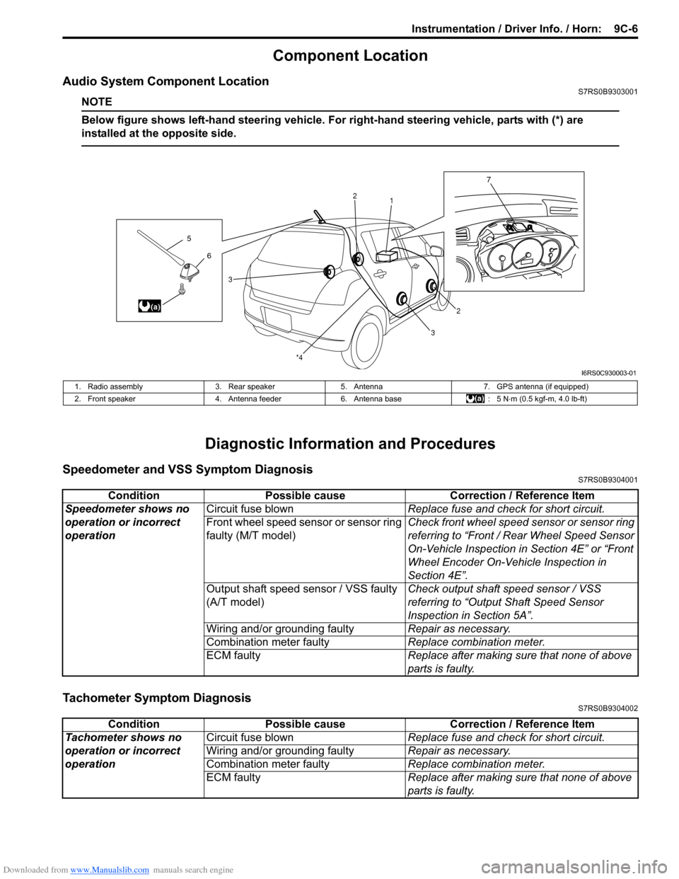
Audio System Component LocationS7RS0B9303001
NOTE
Below figure shows left-hand steering vehicle. For right-hand steering vehicle, parts with (*) are
installed at the opposite side.
Diagnostic Information and Procedures
Speedometer and VSS Symptom DiagnosisS7RS0B9304001
Tachometer Symptom DiagnosisS7RS0B9304002
6
5
(a)
7
1
2
2
3
3
*4
I6RS0C930003-01
1. Radio assembly
3. Rear speaker5. Antenna 7. GPS antenna (if equipped)
2. Front speaker 4. Antenna feeder6. Antenna base : 5 N⋅m (0.5 kgf-m, 4.0 lb-ft)
Condition Possible cause Correction / Reference Item
Speedometer shows no
operation or incorrect
operation Circuit fuse blown
Replace fuse and check for short circuit.
Front wheel speed sensor or sensor ring
faulty (M/T model) Check front wheel speed sensor or sensor ring
referring to “Front / Rear Wheel Speed Sensor
On-Vehicle Inspection in
Section 4E” or “Front
Wheel Encoder On-Vehicle Inspection in
Section 4E”.
Output shaft speed sensor / VSS faulty
(A/T model) Check output shaft
speed sensor / VSS
referring to “Output Shaft Speed Sensor
Inspection in Section 5A”.
Wiring and/or grounding faulty Repair as necessary.
Combination meter faulty Replace combination meter.
ECM faulty Replace after making sure that none of above
parts is faulty.
ConditionPossible cause Correction / Reference Item
Tachometer shows no
operation or incorrect
operation Circuit fuse blown
Replace fuse and check for short circuit.
Wiring and/or grounding faulty Repair as necessary.
Combination meter faulty Replace combination meter.
ECM faulty Replace after making sure that none of above
parts is faulty.
Page 1306 of 1496
Downloaded from www.Manualslib.com manuals search engine 9C-11 Instrumentation / Driver Info. / Horn:
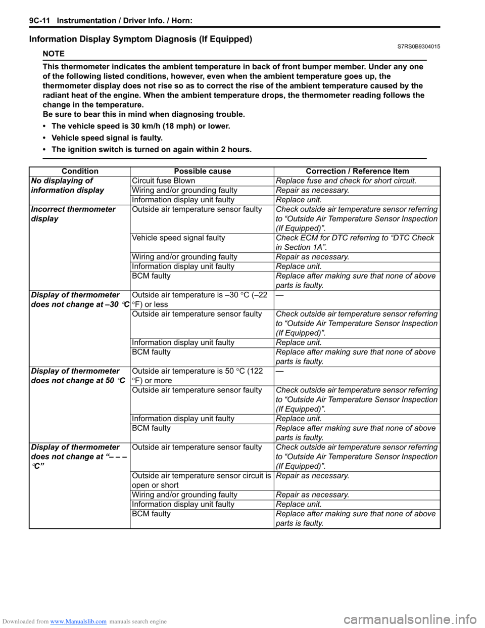
Information Display Symptom Diagnosis (If Equipped)S7RS0B9304015
NOTE
This thermometer indicates the ambient temperature in back of front bumper member. Under any one
of the following listed conditions, however, even when the ambient temperature goes up, the
thermometer display does not rise so as to correct the rise of the ambient temperature caused by the
radiant heat of the engine. When the ambient temperature drops, the thermometer reading follows the
change in the temperature.
Be sure to bear this in mind when diagnosing trouble.
• The vehicle speed is 30 km/h (18 mph) or lower.
• Vehicle speed signal is faulty.
• The ignition switch is turned on again within 2 hours.
ConditionPossible cause Correction / Reference Item
No displaying of
information display Circuit fuse Blown
Replace fuse and check for short circuit.
Wiring and/or grounding faulty Repair as necessary.
Information display unit faulty Replace unit.
Incorrect thermometer
display Outside air temperature sensor faulty
Check outside air temperature sensor referring
to “Outside Air Temperature Sensor Inspection
(If Equipped)”.
Vehicle speed signal faulty Check ECM for DTC referring to “DTC Check
in Section 1A”.
Wiring and/or grounding faulty Repair as necessary.
Information display unit faulty Replace unit.
BCM faulty Replace after making sure that none of above
parts is faulty.
Display of thermometer
does not change at –30
°C Outside air temperature is –30
°C (–22
° F) or less —
Outside air temperature sensor faulty Check outside air temperature sensor referring
to “Outside Air Temperature Sensor Inspection
(If Equipped)”.
Information display unit faulty Replace unit.
BCM faulty Replace after making sure that none of above
parts is faulty.
Display of thermometer
does not change at 50
°C Outside air temperature is 50
°C (122
° F) or more —
Outside air temperature sensor faulty Check outside air temperature sensor referring
to “Outside Air Temperature Sensor Inspection
(If Equipped)”.
Information display unit faulty Replace unit.
BCM faulty Replace after making sure that none of above
parts is faulty.
Display of thermometer
does not change at “– – –
°C” Outside air temperature sensor faulty
Check outside air temperature sensor referring
to “Outside Air Temperature Sensor Inspection
(If Equipped)”.
Outside air temperature sensor circuit is
open or short Repair as necessary.
Wiring and/or grounding faulty Repair as necessary.
Information display unit faulty Replace unit.
BCM faulty Replace after making sure that none of above
parts is faulty.
Page 1405 of 1496
Downloaded from www.Manualslib.com manuals search engine Body Electrical Control System: 10B-2
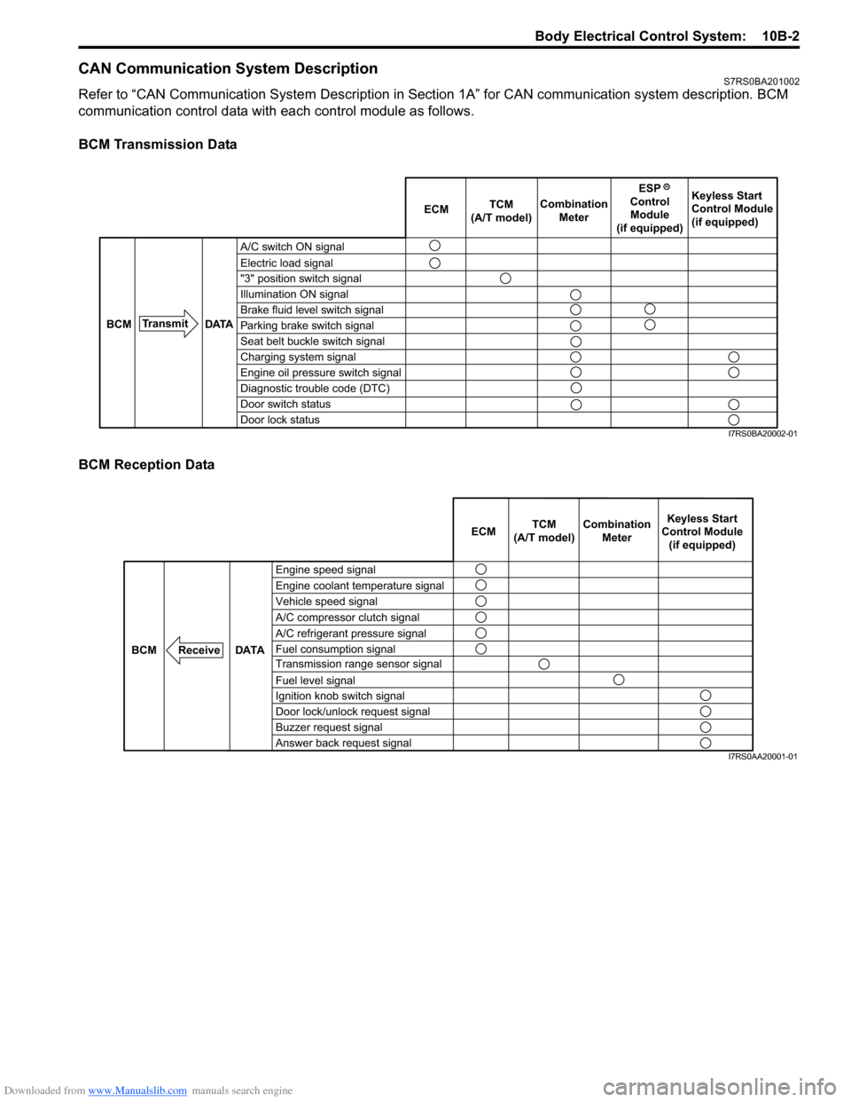
CAN Communication System DescriptionS7RS0BA201002
Refer to “CAN Communication System Description in Section 1A” for CAN communication system description. BCM
communication control data with ea ch control module as follows.
BCM Transmission Data
BCM Reception Data
A/C switch ON signal
Electric load signal
"3" position switch signal
Illumination ON signal
Brake fluid level switch signal
Parking brake switch signal
Seat belt buckle switch signal
Charging system signal
Engine oil pressure switch signal
Diagnostic trouble code (DTC)
Door switch status
Door lock status ECM
TCM
(A/T model) Combination
Meter Keyless Start
Control Module
(if equipped)
Transmit DATA
BCM
ESP
Control Module
(if equipped)
I7RS0BA20002-01
Engine speed signal
Vehicle speed signal Engine coolant temperature signal
A/C refrigerant pressure signal
Fuel consumption signal A/C compressor clutch signal
Transmission range sensor signal
Fuel level signal
Ignition knob switch signal
Door lock/unlock request signal
Buzzer request signal
Answer back request signal
DATA
BCM
Receive
Combination
Meter
TCM
(A/T model) Keyless Start
Control Module (if equipped)
ECM
I7RS0AA20001-01
Page 1416 of 1496
Downloaded from www.Manualslib.com manuals search engine 10B-13 Body Electrical Control System:
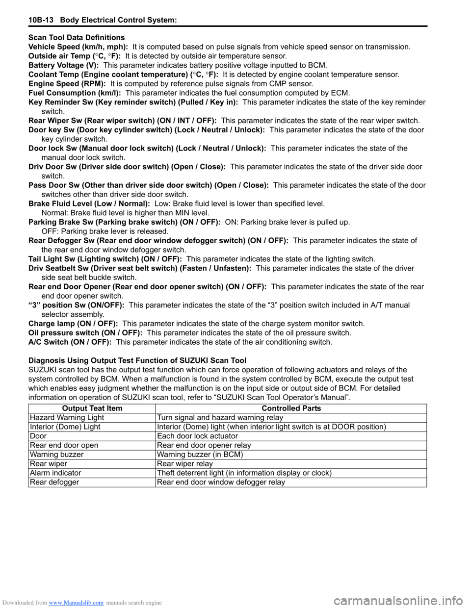
Scan Tool Data Definitions
Vehicle Speed (km/h, mph): It is computed based on pulse signals from vehicle speed sensor on transmission.
Outside air Temp ( °C, °F): It is detected by outside air temperature sensor.
Battery Voltage (V): This parameter indicates battery po sitive voltage inputted to BCM.
Coolant Temp (Engine coolant temperature) ( °C, °F): It is detected by engine coolant temperature sensor.
Engine Speed (RPM): It is computed by reference pulse signals from CMP sensor.
Fuel Consumption (km/l): This parameter indicates the fuel consumption computed by ECM.
Key Reminder Sw (Key reminder switch) (Pulled / Key in): This parameter indicates the state of the key reminder
switch.
Rear Wiper Sw (Rear wiper switch) (ON / INT / OFF): This parameter indicates the state of the rear wiper switch.
Door key Sw (Door key cylinder switch) (Lock / Neutral / Unlock): This parameter indicates the state of the door
key cylinder switch.
Door lock Sw (Manual door lock switch) (Lock / Neutral / Unlock): This parameter indicates the state of the
manual door lock switch.
Driv Door Sw (Driver side d oor switch) (Open / Close): This parameter indicates the state of the driver side door
switch.
Pass Door Sw (Other than driver side door switch) (Open / Close): This parameter indicates the state of the door
switches other than driver side door switch.
Brake Fluid Level (Low / Normal): Low: Brake fluid level is lower than specified level.
Normal: Brake fluid level is higher than MIN level.
Parking Brake Sw (Parking brake switch) (ON / OFF): ON: Parking brake lever is pulled up.
OFF: Parking brake lever is released.
Rear Defogger Sw (Rear end door window defogger switch) (ON / OFF): This parameter indicates the state of
the rear end door window defogger switch.
Tail Light Sw (Lighting switch) (ON / OFF): This parameter indicates the state of the lighting switch.
Driv Seatbelt Sw (Driver seat belt switch) (Fasten / Unfasten): This parameter indicates the state of the driver
side seat belt buckle switch.
Rear end Door Opener (Rear end door opener switch) (ON / OFF): This parameter indicates the state of the rear
end door opener switch.
“3” position Sw (ON/OFF): This parameter indicates the state of the “3 ” position switch included in A/T manual
selector assembly.
Charge lamp (ON / OFF): This parameter indicates the state of the charge system monitor switch.
Oil pressure switch (ON / OFF): This parameter indicates the state of the oil pressure switch.
A/C Switch (ON / OFF): This parameter indicates the state of the air conditioning switch.
Diagnosis Using Output Test Function of SUZUKI Scan Tool
SUZUKI scan tool has the output test function which can force operation of following actuators and relays of the
system controlled by BCM. When a malf unction is found in the system controlled by BCM, execute the output test
which enables easy judgment whether the malfunction is on the input side or output side of BCM. For detailed
information on operation of SUZUKI scan tool, refer to “SUZUKI Scan Tool Operator’s Manual”.
Output Teat Item Controlled Parts
Hazard Warning Light Turn signal and hazard warning relay
Interior (Dome) Light Interior (Dome) light (wh en interior light switch is at DOOR position)
Door Each door lock actuator
Rear end door open Rear end door opener relay
Warning buzzer Warning buzzer (in BCM)
Rear wiper Rear wiper relay
Alarm indicator Theft deterrent light (in information display or clock)
Rear defogger Rear end door window defogger relay
Page 1436 of 1496
Downloaded from www.Manualslib.com manuals search engine 10B-33 Body Electrical Control System:
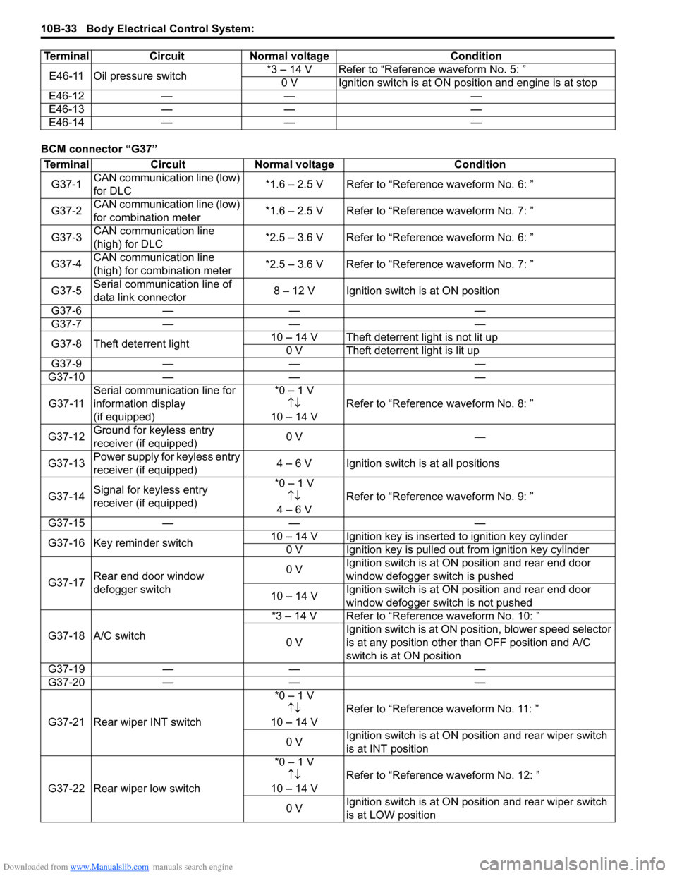
BCM connector “G37”E46-11 Oil pressure switch
*3 – 14 V Refer to “Reference waveform No. 5: ”
0 V Ignition switch is at ON position and engine is at stop
E46-12 — — —
E46-13 — — —
E46-14 — — —
Terminal Circuit Normal voltage Condition
Terminal
CircuitNormal voltage Condition
G37-1 CAN communication line (low)
for DLC *1.6 – 2.5 V Refer to “Reference waveform No. 6: ”
G37-2 CAN communication line (low)
for combination meter *1.6 – 2.5 V Refer to “Reference waveform No. 7: ”
G37-3 CAN communication line
(high) for DLC *2.5 – 3.6 V Refer to “Reference waveform No. 6: ”
G37-4 CAN communication line
(high) for combination meter *2.5 – 3.6 V Refer to “Reference waveform No. 7: ”
G37-5 Serial communication line of
data link connector 8 – 12 V Ignition switch is at ON position
G37-6 — — —
G37-7 — — —
G37-8 Theft deterrent light 10 – 14 V Theft deterrent light is not lit up
0 V Theft deterrent light is lit up
G37-9 — — —
G37-10 — — —
G37-11 Serial communication line for
information display
(if equipped) *0 – 1 V
↑↓
10 – 14 V Refer to “Reference
waveform No. 8: ”
G37-12 Ground for keyless entry
receiver (if equipped) 0 V
—
G37-13 Power supply for keyless entry
receiver (if equipped) 4 – 6 V Ignition switch is at all positions
G37-14 Signal for keyless entry
receiver (if equipped) *0 – 1 V
↑↓
4 – 6 V Refer to “Reference
waveform No. 9: ”
G37-15 — — —
G37-16 Key reminder switch 10 – 14 V Ignition key is inserted to ignition key cylinder
0 V Ignition key is pulled out from ignition key cylinder
G37-17 Rear end door window
defogger switch 0 V
Ignition switch is at ON
position and rear end door
window defogger switch is pushed
10 – 14 V Ignition switch is at ON
position and rear end door
window defogger switch is not pushed
G37-18 A/C switch *3 – 14 V Refer to “Reference waveform No. 10: ”
0 V Ignition switch is at ON pos
ition, blower speed selector
is at any position other than OFF position and A/C
switch is at ON position
G37-19 — — —
G37-20 — — —
G37-21 Rear wiper INT switch *0 – 1 V
↑↓
10 – 14 V Refer to “Reference
waveform No. 11: ”
0 V Ignition switch is at ON pos
ition and rear wiper switch
is at INT position
G37-22 Rear wiper low switch *0 – 1 V
↑↓
10 – 14 V Refer to “Reference
waveform No. 12: ”
0 V Ignition switch is at ON pos
ition and rear wiper switch
is at LOW position
Page 1440 of 1496
Downloaded from www.Manualslib.com manuals search engine 10B-37 Body Electrical Control System:
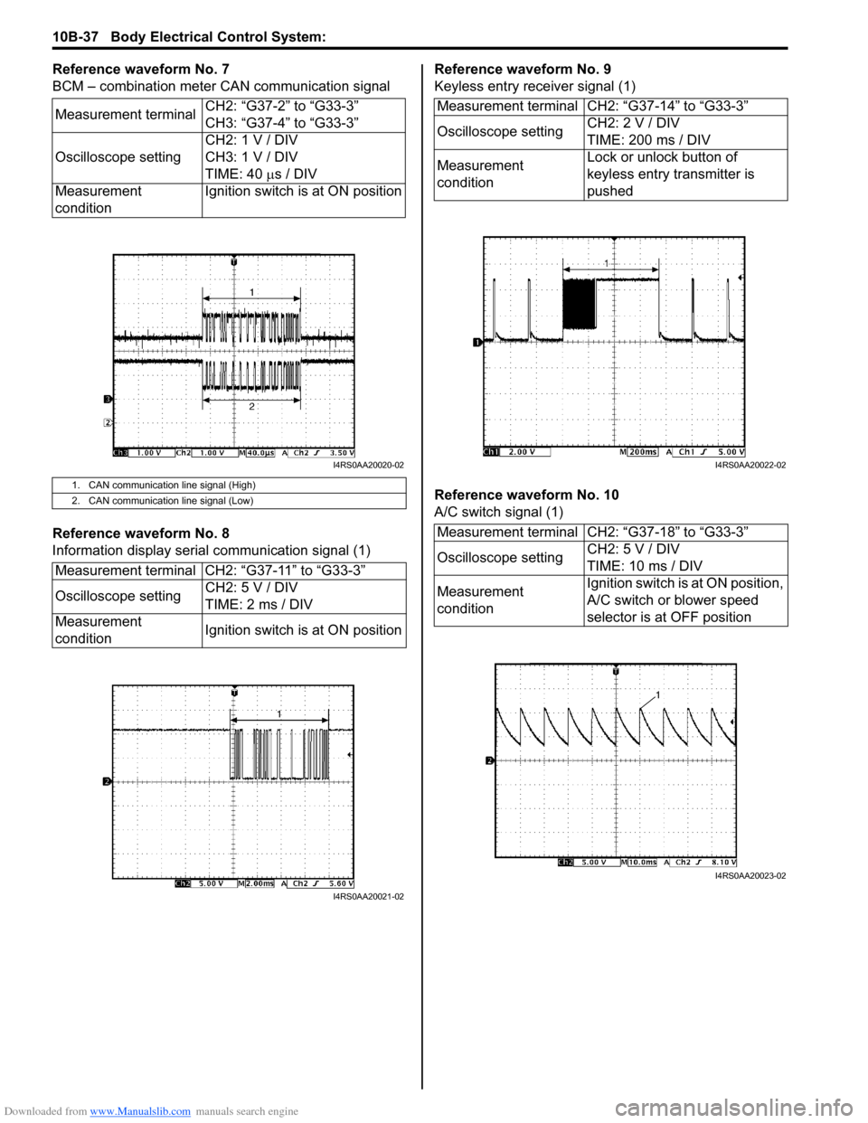
Reference waveform No. 7
BCM – combination meter CAN communication signal
Reference waveform No. 8
Information display serial communication signal (1)Reference waveform No. 9
Keyless entry receiver signal (1)
Reference waveform No. 10
A/C switch signal (1)
Measurement terminal
CH2: “G37-2” to “G33-3”
CH3: “G37-4” to “G33-3”
Oscilloscope setting CH2: 1 V / DIV
CH3: 1 V / DIV
TIME: 40
µs / DIV
Measurement
condition Ignition switch is at ON position
1. CAN communication line signal (High)
2. CAN communication line signal (Low)
Measurement terminal CH2: “G37-11” to “G33-3”
Oscilloscope setting
CH2: 5 V / DIV
TIME: 2 ms / DIV
Measurement
condition Ignition switch is at ON position
I4RS0AA20020-02
I4RS0AA20021-02
Measurement terminal CH2: “G37-14” to “G33-3”
Oscilloscope settingCH2: 2 V / DIV
TIME: 200 ms / DIV
Measurement
condition Lock or unlock button of
keyless entry transmitter is
pushed
Measurement terminal CH2: “G37-18” to “G33-3”
Oscilloscope setting CH2: 5 V / DIV
TIME: 10 ms / DIV
Measurement
condition Ignition switch is at ON position,
A/C switch or blower speed
selector is at OFF position
I4RS0AA20022-02
I4RS0AA20023-02
Page 1468 of 1496
Downloaded from www.Manualslib.com manuals search engine 10E-6 Keyless Start System:
Alarm FunctionS7RS0BA501006
Under conditions as described in the table below, the keyless start control module makes the key indicator lamp flash
in red and the buzzer sound to call the driver’s attention.
CAN Communication System DescriptionS7RS0BA501007
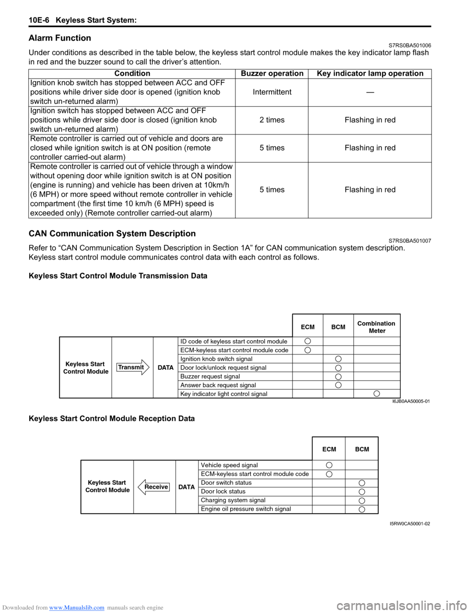
Refer to “CAN Communication System Description in Section 1A” for CAN communication system description.
Keyless start control module communicates control data wit h each control as follows.
Keyless Start Control Module Transmission Data
Keyless Start Control Module Reception Data Condition Buzzer operation Key indicator lamp operation
Ignition knob switch has stopped between ACC and OFF
positions while driver side door is opened (ignition knob
switch un-returned alarm) Intermittent —
Ignition switch has stopped between ACC and OFF
positions while driver side door is closed (ignition knob
switch un-returned alarm) 2 times Flashing in red
Remote controller is carried out of vehicle and doors are
closed while ignition switch is at ON position (remote
controller carried-out alarm) 5 times Flashing in red
Remote controller is carried out of vehicle through a window
without opening door while ignition switch is at ON position
(engine is running) and vehicle has been driven at 10km/h
(6 MPH) or more speed without remote controller in vehicle
compartment (the first time 10 km/h (6 MPH) speed is
exceeded only) (Remote cont roller carried-out alarm) 5 times Flashing in red
BCM
ECM Combination
Meter
ID code of keyless start control module
ECM-keyless start control module code
Ignition knob switch signal
Door lock/unlock request signal
Buzzer request signal
Answer back request signal
Key indicator light control signal
DATA
Transmit
Keyless Start
Control Module
I6JB0AA50005-01
Vehicle speed signal
ECM-keyless start control module code
Door switch status
Door lock status
Charging system signal
Engine oil pressure switch signal ECM BCM
DATA
ReceiveKeyless Start
Control Module
I5RW0CA50001-02