1.1 SUZUKI SWIFT 2006 2.G Service Manual PDF
[x] Cancel search | Manufacturer: SUZUKI, Model Year: 2006, Model line: SWIFT, Model: SUZUKI SWIFT 2006 2.GPages: 1496, PDF Size: 34.44 MB
Page 1146 of 1496

Downloaded from www.Manualslib.com manuals search engine 8B-108 Air Bag System:
4) Remove side curtain-air bag (inflator) module fixing bolts (1) and clips (2).
5) Remove side curtain-air bag (inflator) module.
WARNING!
• When carrying a live air bag (inflator) module, make sure the bag opening is
pointed away from you.
Never carry air bag (inflator) module by
wires or connector on the side of the
module. In case of an accidental
deployment, the bag will then deploy with
minimal chance of injury.
• As the live curtain air bag (inflator) module must be kept with it s bag facing up while
being stored or left standing. This is
necessary so that a free space is provided
to allow the air bag to expand in the
unlikely event of accidental deployment.
• Observe “Precautions on Handling and Storage of Air Bag System Components”
for handling and storing it.
Otherwise, personal injury may result.
Installation
WARNING!
Do not install side curtain-air bag (inflator)
module while twisted or bended. Otherwise,
side curtain-air bag (inflator) module may not
deploy and injury may result.
1) Install side curtain-air bag (inflator) module (1) with
clips and new bolts.
2) Tighten side curtain-air bag (inflator) module attaching bolts (1) to specified torque.
Tightening torque
Side curtain-air bag (inflator) module attaching
bolts (a): 11 N·m (1.1 kgf-m, 8.0 lb-ft)
3) Connect side curtain-air bag (inflator) module connector (1) securely as shown in figure.
a) Connect connector.
b) Lock connector wi th lock button (2).
4) Install head lining referring to “Head Lining Removal and Installation in Section 9H”.
5) Enable air bag system. Refer to “Enabling Air Bag System”.1 2
2
22
1
I4RS0A820076-01
1,(a) 1,(a)
I4RS0A820110-01
1
2
a)
b)
I4RS0A820055-01
Page 1163 of 1496
Downloaded from www.Manualslib.com manuals search engine Air Bag System: 8B-125
Specifications
Tightening Torque SpecificationsS7RS0B8207001
NOTE
The specified tightening torque is also described in the following.
“Air Bag System Components, Wiring and Connectors Location”
Reference:
For the tightening torque of fastener not specified in this section, refer to “Fasteners Information in Section 0A”.
Special Tools and Equipment
Use of Special ToolsS7RS0B8208001
WARNING!
To avoid deployment when troubleshooting
the air bag system, do not use electrical test
equipment such as a battery powered or AC
powered voltmeter, ohmmeter, etc., or any
type of electrical equipment other than that
specified. Do not use a non-powered probe
type tester.
Instructions must be followed carefully,
otherwise personal injury may result.
You should be familiar with the tools listed under the
heading “Special Tool”. You should be able to measure
voltage and resistance. You should be familiar with
proper use of a scan tool such as Air Bag Driver /
Passenger Load Tool, Connector Test Adapter Kit and
the Digital Multimeter.
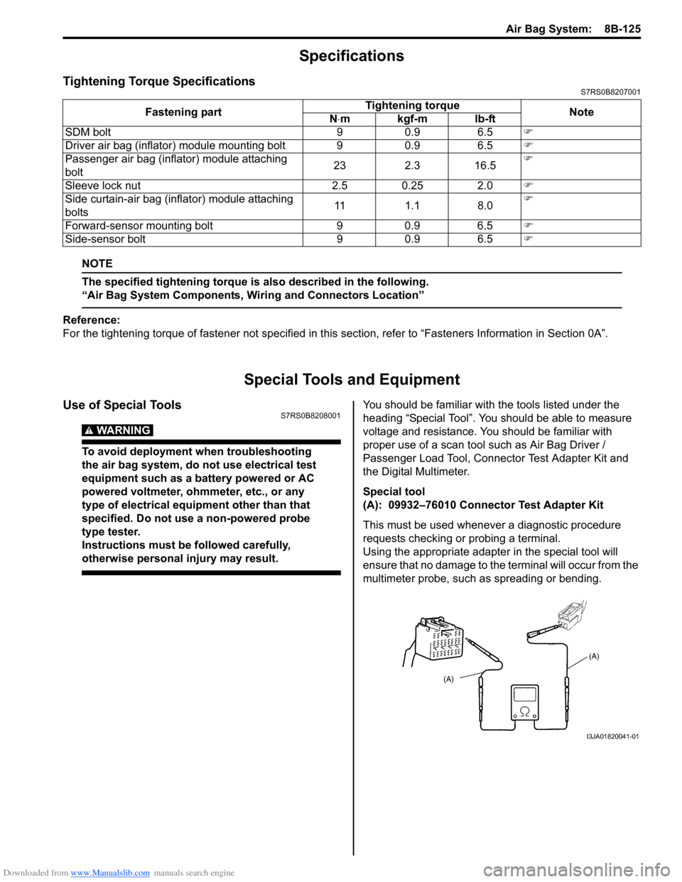
Special tool
(A): 09932–76010 Connector Test Adapter Kit
This must be used whenever a diagnostic procedure
requests checking or probing a terminal.
Using the appropriate adapter in the special tool will
ensure that no damage to the terminal will occur from the
multimeter probe, such as spreading or bending.
Fastening part
Tightening torque
Note
N ⋅mkgf-mlb-ft
SDM bolt 9 0.9 6.5 �)
Driver air bag (inflator) module mounting bolt 9 0.9 6.5 �)
Passenger air bag (inflator) module attaching
bolt 23 2.3 16.5�)
Sleeve lock nut 2.5 0.25 2.0 �)
Side curtain-air bag (inflator) module attaching
bolts 11 1.1 8.0�)
Forward-sensor mounting bolt 9 0.9 6.5 �)
Side-sensor bolt 9 0.9 6.5 �)
I3JA01820041-01
Page 1294 of 1496
Downloaded from www.Manualslib.com manuals search engine 9B-12 Lighting Systems:
Front Fog Light Aiming Adjustment with Screen
(If Equipped)
S7RS0B9206018
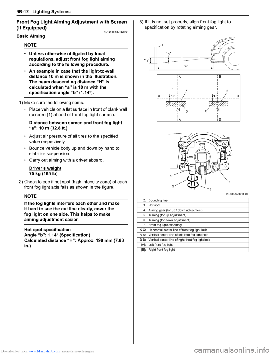
Basic Aiming
NOTE
• Unless otherwise obligated by local regulations, adjust front fog light aiming
according to the following procedure.
• An example in case that the light-to-wall distance 10 m is shown in the illustration.
The beam descending distance “H” is
calculated when “a” is 10 m with the
specification angle “b” (1.14 °).
1) Make sure the following items.
• Place vehicle on a flat surface in front of blank wall (screen) (1) ahead of front fog light surface.
Distance between screen and front fog light
“a”: 10 m (32.8 ft.)
• Adjust air pressure of all tires to the specified value respectively.
• Bounce vehicle body up and down by hand to stabilize suspension.
• Carry out aiming with a driver aboard.
Driver’s weight
75 kg (165 lb)
2) Check to see if hot spot (h igh intensity zone) of each
front fog light axis falls as shown in the figure.
NOTE
If the fog lights interfere each other and make
it hard to see the cut line clearly, cover the
fog light on one side. This helps to make
aiming adjustment easier.
Hot spot specification
Angle “b”: 1.14° (Specification)
Calculated distance “H”: Approx. 199 mm (7.83
in.) 3) If it is not set properly
, align front fog light to
specification by rotating aiming gear.
2. Bounding line
3. Hot spot
4. Aiming gear (for up / down adjustment)
5. Turning (for up adjustment)
6. Turning (for down adjustment)
7. Front fog light assembly
X-X: Horizontal center line of front fog light bulb
A-A: Vertical center line of left front fog light bulb
B-B: Vertical center line of right front fog light bulb [A]: Left front fog light
[B]: Right front fog light
I4RS0B920011-01
Page 1332 of 1496
Downloaded from www.Manualslib.com manuals search engine 9E-5 Glass / Windows / Mirrors:
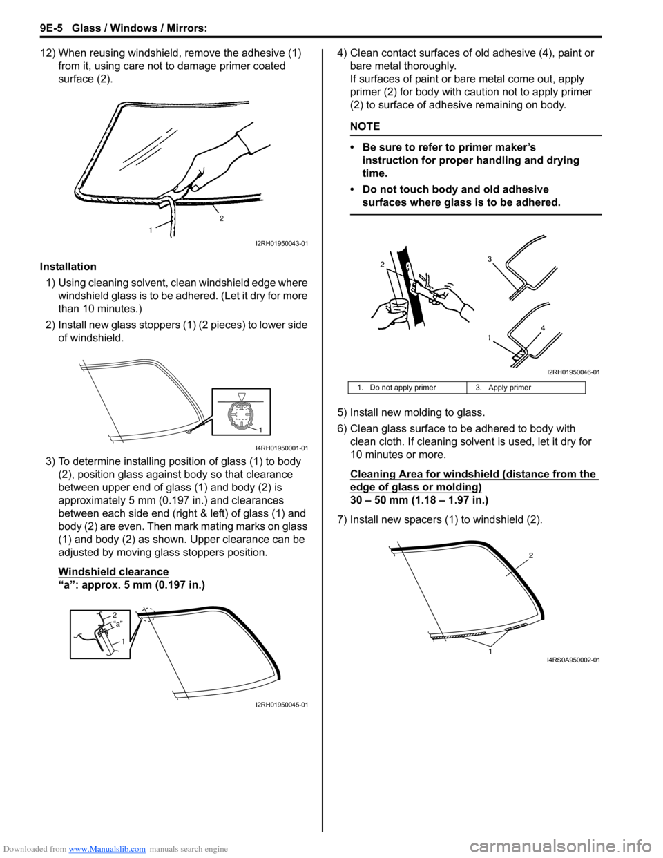
12) When reusing windshield, remove the adhesive (1) from it, using care not to damage primer coated
surface (2).
Installation 1) Using cleaning solvent, clean windshield edge where windshield glass is to be adhered. (Let it dry for more
than 10 minutes.)
2) Install new glass stoppers (1) (2 pieces) to lower side of windshield.
3) To determine installing position of glass (1) to body (2), position glass against body so that clearance
between upper end of glass (1) and body (2) is
approximately 5 mm (0.197 in.) and clearances
between each side end (right & left) of glass (1) and
body (2) are even. Then mark mating marks on glass
(1) and body (2) as shown. Upper clearance can be
adjusted by moving glass stoppers position.
Windshield clearance
“a”: approx. 5 mm (0.197 in.) 4) Clean contact surfaces of old adhesive (4), paint or
bare metal thoroughly.
If surfaces of paint or ba re metal come out, apply
primer (2) for body with caution not to apply primer
(2) to surface of adhesive remaining on body.
NOTE
• Be sure to refer to primer maker’s instruction for proper handling and drying
time.
• Do not touch body and old adhesive surfaces where glass is to be adhered.
5) Install new molding to glass.
6) Clean glass surface to be adhered to body with clean cloth. If cleaning solvent is used, let it dry for
10 minutes or more.
Cleaning Area for windshie ld (distance from the
edge of glass or molding)
30 – 50 mm (1.18 – 1.97 in.)
7) Install new spacers (1) to windshield (2).
I2RH01950043-01
1
I4RH01950001-01
2
1“a”
I2RH01950045-01
1. Do not apply primer 3. Apply primer
I2RH01950046-01
2
1I4RS0A950002-01
Page 1385 of 1496
Downloaded from www.Manualslib.com manuals search engine Body Structure: 9K-8
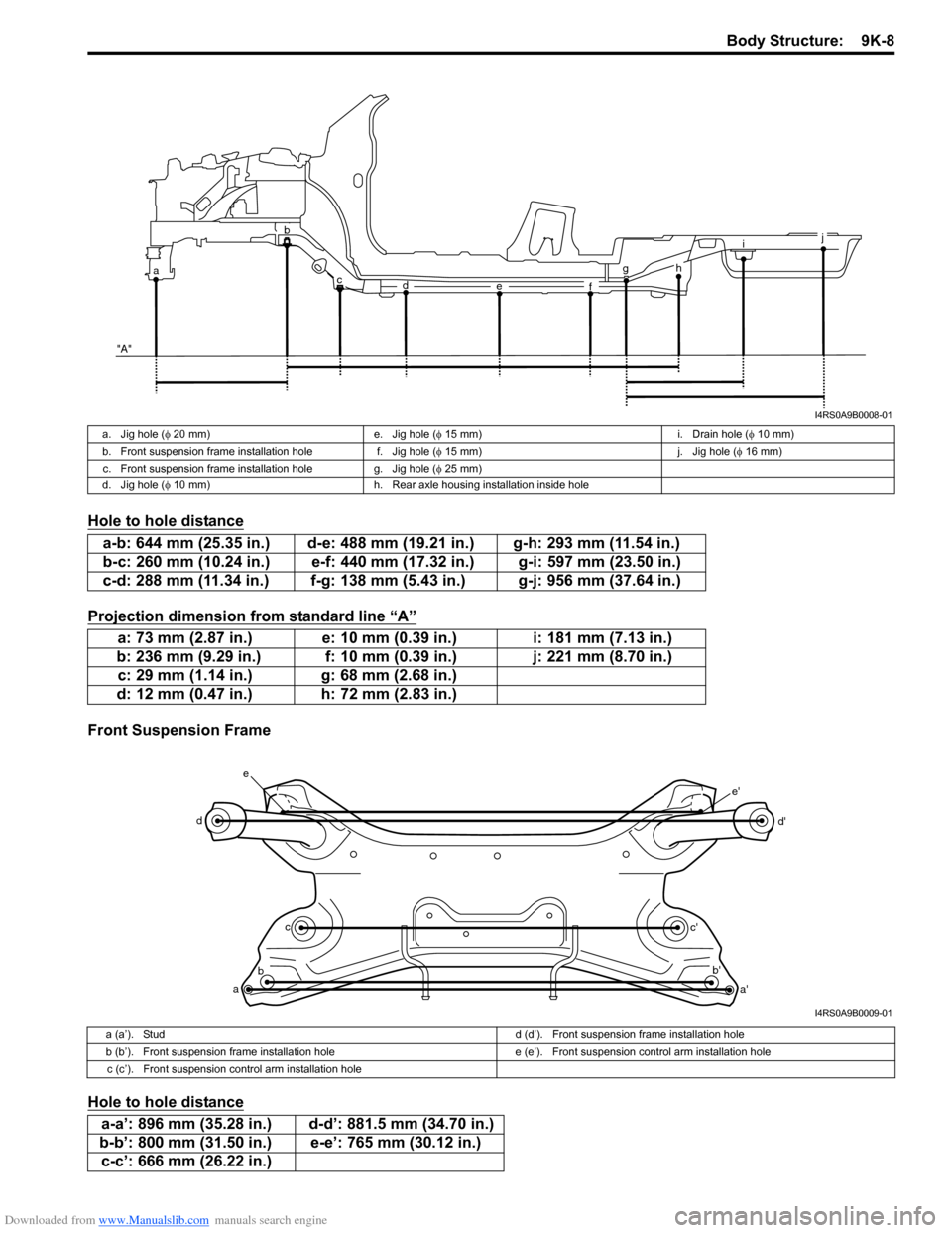
Hole to hole distance
Projection dimension from standard line “A”
Front Suspension Frame
Hole to hole distance
i
g
f
e
d
c
ab
"A"j
h
I4RS0A9B0008-01
a. Jig hole ( φ 20 mm) e. Jig hole ( φ 15 mm) i. Drain hole ( φ 10 mm)
b. Front suspension frame installation hole f. Jig hole (φ 15 mm) j. Jig hole (φ 16 mm)
c. Front suspension frame installation hole g. Jig hole ( φ 25 mm)
d. Jig hole ( φ 10 mm) h. Rear axle housing installation inside hole
a-b: 644 mm (25.35 in.) d-e: 488 mm (19.21 in.) g-h: 293 mm (11.54 in.)
b-c: 260 mm (10.24 in.) e-f: 440 mm (17.32 in.) g-i: 597 mm (23.50 in.)
c-d: 288 mm (11.34 in.) f-g: 138 mm (5.43 in.) g-j: 956 mm (37.64 in.)
a: 73 mm (2.87 in.) e: 10 mm (0.39 in.) i: 181 mm (7.13 in.)
b: 236 mm (9.29 in.) f: 10 mm (0.39 in.) j: 221 mm (8.70 in.) c: 29 mm (1.14 in.) g: 68 mm (2.68 in.)
d: 12 mm (0.47 in.) h: 72 mm (2.83 in.)
a b c
d
e
a'
b'
c' d'
e'
I4RS0A9B0009-01
a (a’). Stud
d (d’). Front suspension frame installation hole
b (b’). Front suspension frame installation hole e (e’). Front suspension control arm installation hole
c (c’). Front suspension control arm installation hole
a-a’: 896 mm (35.28 in.) d-d’: 881.5 mm (34.70 in.)
b-b’: 800 mm (31.50 in.) e-e’: 765 mm (30.12 in.) c-c’: 666 mm (26.22 in.)
Page 1387 of 1496
Downloaded from www.Manualslib.com manuals search engine Body Structure: 9K-10
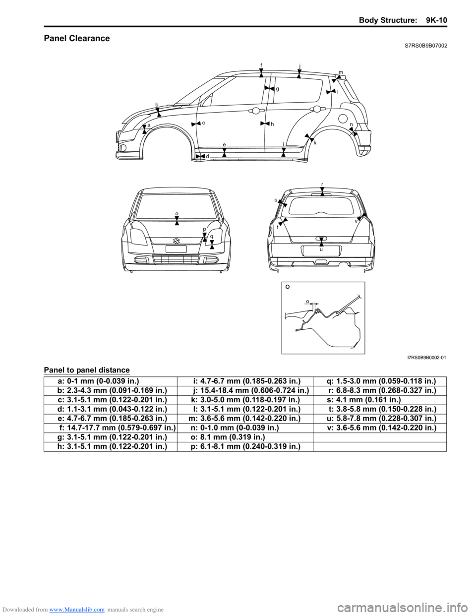
Panel ClearanceS7RS0B9B07002
Panel to panel distance
o
bc
e h
f
j
i l
m
k n
r
u
s
t
o
q
o
g
a
d
p
v
I7RS0B9B0002-01
a: 0-1 mm (0-0.039 in.) i: 4.7-6.7 mm (0.185-0.263 in.) q: 1.5-3.0 mm (0.059-0.118 in.)
b: 2.3-4.3 mm (0.091-0.169 in.) j: 15.4-18.4 mm (0.606-0.724 in.) r: 6.8-8.3 mm (0.268-0.327 in.) c: 3.1-5.1 mm (0.122-0.201 in.) k: 3.0-5.0 mm (0.118-0.197 in.) s: 4.1 mm (0.161 in.)
d: 1.1-3.1 mm (0.043-0.122 in.) l: 3.1-5.1 mm (0.122-0.201 in.) t: 3.8-5.8 mm (0.150-0.228 in.) e: 4.7-6.7 mm (0.185-0.263 in.) m: 3.6-5.6 mm (0.142-0.220 in.) u: 5.8-7.8 mm (0.228-0.307 in.) f: 14.7-17.7 mm (0.579-0.697 in.) n: 0-1.0 mm (0-0.039 in.) v: 3.6-5.6 mm (0.142-0.220 in.)
g: 3.1-5.1 mm (0.122-0.201 in.) o: 8.1 mm (0.319 in.)
h: 3.1-5.1 mm (0.122-0.201 in.) p: 6.1-8.1 mm (0.240-0.319 in.)