200 SUZUKI SWIFT 2006 2.G Service Manual Online
[x] Cancel search | Manufacturer: SUZUKI, Model Year: 2006, Model line: SWIFT, Model: SUZUKI SWIFT 2006 2.GPages: 1496, PDF Size: 34.44 MB
Page 654 of 1496
Downloaded from www.Manualslib.com manuals search engine 5A-10 Automatic Transmission/Transaxle:
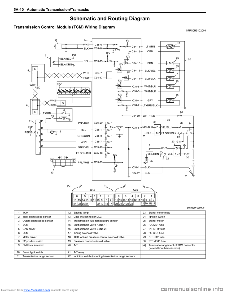
Schematic and Routing Diagram
Transmission Control Module (TCM) Wiring DiagramS7RS0B5102001
IG1
115
5
5
8
9
10 7
P
R
N
D
2
L
12
12V 2.5V
5V
12V
5V
12V
12V
12V
12V
WHT
BLK
BLK
BLK
BLK
PPLBLK/RED
BLK/ORN
IG11
RED/BLK
YEL/BLKYEL/BLU
LT GRN/BLK
+BB
WHT/RED
14
20
15
16
17
19
12V18
1
2
3
4
6
13 21
26
24
27
28 29
30
WHT
WHT
RED
RED
WHT
RED
65
16 15 14 13 12 11 43
24 23 2122 10 9 8 721
1920 18 17
C34
17 16
26 25
15 14
65 3
42
13 12
23 2224 11 10 9
21 20 19 87
18
1
C35
[A]
22
25
YELYEL/GRN
WHT
P
N
BRN
LT GRN
ORN
BLK/YEL
BLU/BLK
GRY
LT GRN/BLK WHT/BLU
WHT/BLK
C34-11
C34-12
C34-16
C34-15
C34-14
C34-4
C34-2
C34-1
C34-23 C34-6
C34-24 C34-5
C34-3
RED
GRN
GRN/ORN PNK/BLK
GRN/YEL
LT GRN/BLKC35-6
C35-16
C35-23 C35-25
C35-20
C35-1
C35-8
C35-7
C35-19
C35-18 C34-17 C34-7
4IG11
12V
23
PPL/WHT
LT GRN
I6RS0C510005-01
1. TCM 12. Backup lamp 23. Starter motor relay
2. Input shaft speed sensor 13. Data link connector DLC 24. Ignition switch
3. Output shaft speed sensor 14. Transmission fluid temperature sensor 25. Starter motor
4. ECM 15. Shift solenoid valve-A (No.1) 26. “DOME” fuse
5. CAN driver 16. Shift solenoid valve-B (No.2) 27. “AT ETM” fuse
6. BCM 17. Timing solenoid valve 28. “IG SIG” fuse
7. Meter driver 18. TCC lock-up pressure control solenoid valve 29. “ST SIG” fuse
8. “3” position switch 19. Pressure control solenoid valve 30. “ST MOT” fuse
9. Shift lock solenoid 20. A/T [A]: Terminal arrangement of TCM connector
(viewed from harness side)
10. Brake light switch 21. A/T relay
11. Transmission range sensor 22. Inhibitor switch (including transmission range sensor)
Page 656 of 1496
Downloaded from www.Manualslib.com manuals search engine 5A-12 Automatic Transmission/Transaxle:
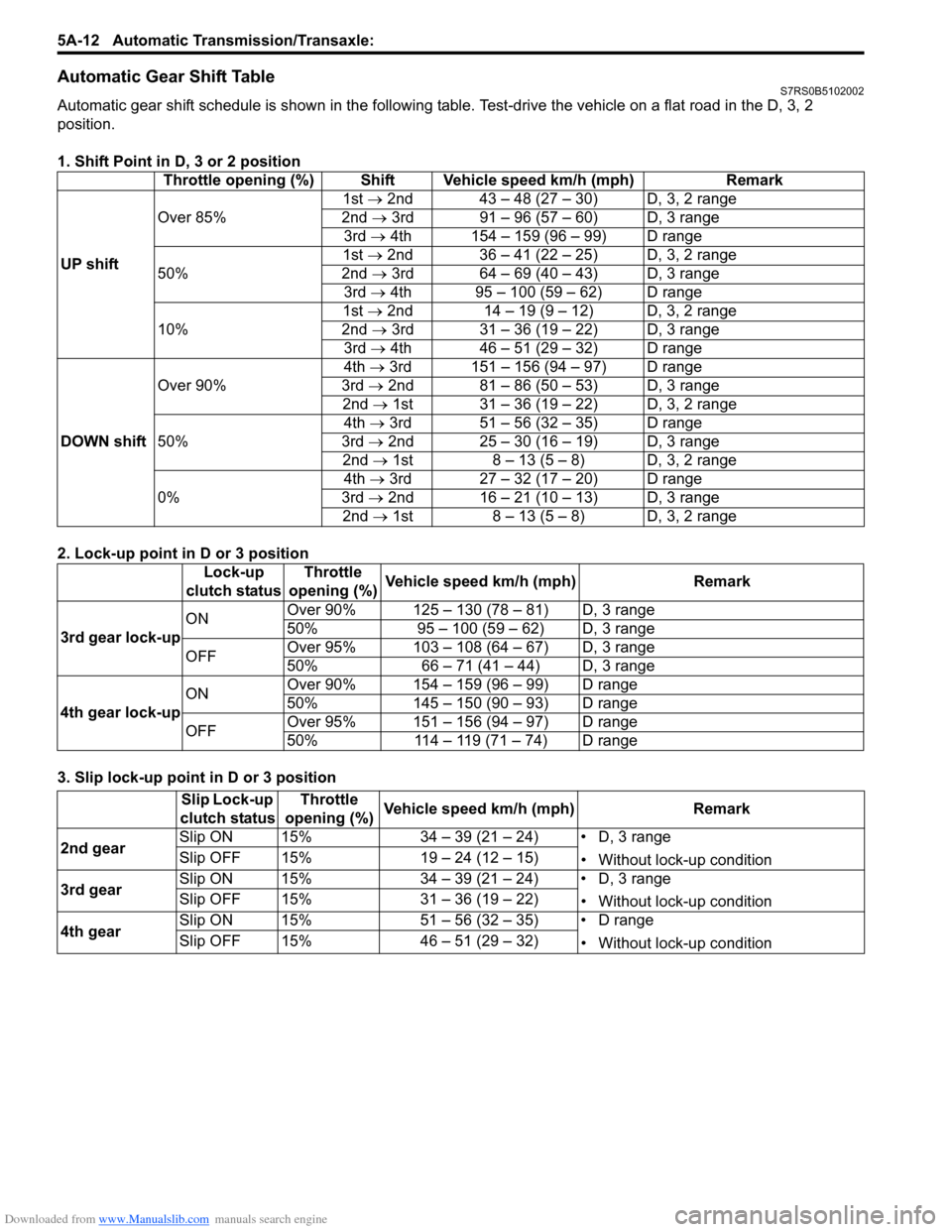
Automatic Gear Shift TableS7RS0B5102002
Automatic gear shift schedule is shown in the following table. Test-drive the vehicle on a flat road in the D, 3, 2
position.
1. Shift Point in D, 3 or 2 position
2. Lock-up point in D or 3 position
3. Slip lock-up point in D or 3 position Throttle opening (%) Shift Vehicle speed km/h (mph) Remark
UP shift Over 85%
1st →
2nd 43 – 48 (27 – 30) D, 3, 2 range
2nd → 3rd 91 – 96 (57 – 60) D, 3 range
3rd → 4th 154 – 159 (96 – 99) D range
50% 1st →
2nd 36 – 41 (22 – 25) D, 3, 2 range
2nd → 3rd 64 – 69 (40 – 43) D, 3 range
3rd → 4th 95 – 100 (59 – 62) D range
10% 1st →
2nd 14 – 19 (9 – 12) D, 3, 2 range
2nd → 3rd 31 – 36 (19 – 22) D, 3 range
3rd → 4th 46 – 51 (29 – 32) D range
DOWN shift Over 90%
4th
→ 3rd 151 – 156 (94 – 97) D range
3rd → 2nd 81 – 86 (50 – 53) D, 3 range
2nd → 1st 31 – 36 (19 – 22) D, 3, 2 range
50% 4th
→ 3rd 51 – 56 (32 – 35) D range
3rd → 2nd 25 – 30 (16 – 19) D, 3 range
2nd → 1st 8 – 13 (5 – 8) D, 3, 2 range
0% 4th
→ 3rd 27 – 32 (17 – 20) D range
3rd → 2nd 16 – 21 (10 – 13) D, 3 range
2nd → 1st 8 – 13 (5 – 8) D, 3, 2 range
Lock-up
clutch status Throttle
opening (%) Vehicle speed km/h (mph) Remark
3rd gear lock-up ON
Over 90% 125 – 130 (78 – 81) D, 3 range
50% 95 – 100 (59 – 62) D, 3 range
OFF Over 95% 103 – 108 (64 – 67) D, 3 range
50% 66 – 71 (41 – 44) D, 3 range
4th gear lock-up ON
Over 90% 154 – 159 (96 – 99) D range
50% 145 – 150 (90 – 93) D range
OFF Over 95% 151 – 156 (94 – 97) D range
50% 114 – 119 (71 – 74) D range
Slip Lock-up
clutch status Throttle
opening (%) Vehicle speed km/h (mph) Remark
2nd gear Slip ON 15% 34 – 39 (21 – 24) • D, 3 range
• Without lock-up condition
Slip OFF 15% 19 – 24 (12 – 15)
3rd gear Slip ON 15% 34 – 39 (21 – 24) • D, 3 range
• Without lock-up condition
Slip OFF 15% 31 – 36 (19 – 22)
4th gear Slip ON 15% 51 – 56 (32 – 35) • D range
• Without lock-up condition
Slip OFF 15% 46 – 51 (29 – 32)
Page 665 of 1496
Downloaded from www.Manualslib.com manuals search engine Automatic Transmission/Transaxle: 5A-21
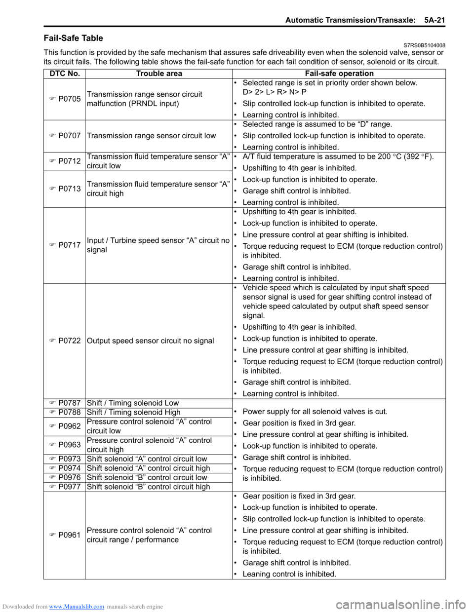
Fail-Safe TableS7RS0B5104008
This function is provided by the safe mechanism that assures safe driveability even when the solenoid valve, sensor or
its circuit fails. The following table shows th e fail-safe function for each fail condition of sensor, solenoid or its circuit.
DTC No. Trouble area Fail-safe operation
�) P0705 Transmission range sensor circuit
malfunction (PRNDL input) • Selected range is set in priority order shown below.
D> 2> L> R> N> P
• Slip controlled lock-up function is inhibited to operate.
• Learning control is inhibited.
�) P0707 Transmission range sensor circuit low • Selected range is assumed to be “D” range.
• Slip controlled lock-up function is inhibited to operate.
• Learning control is inhibited.
�) P0712 Transmission fluid temperature sensor “A”
circuit low • A/T fluid temperature is assumed to be 200
°C (392 °F).
• Upshifting to 4th gear is inhibited.
• Lock-up function is inhibited to operate.
• Garage shift control is inhibited.
• Learning control is inhibited.
�)
P0713 Transmission fluid temperature sensor “A”
circuit high
�) P0717 Input / Turbine speed sensor “A” circuit no
signal • Upshifting to 4th gear is inhibited.
• Lock-up function is inhibited to operate.
• Line pressure control at gear shifting is inhibited.
• Torque reducing request to ECM (torque reduction control)
is inhibited.
• Garage shift control is inhibited.
• Learning control is inhibited.
�) P0722 Output speed sensor circuit no signal • Vehicle speed which is calculated by input shaft speed
sensor signal is used for gear shifting control instead of
vehicle speed calculated by output shaft speed sensor
signal.
• Upshifting to 4th gear is inhibited.
• Lock-up function is inhibited to operate.
• Line pressure control at gear shifting is inhibited.
• Torque reducing request to ECM (torque reduction control) is inhibited.
• Garage shift control is inhibited.
• Learning control is inhibited.
�) P0787 Shift / Timing solenoid Low
• Power supply for all solenoid valves is cut.
• Gear position is fixed in 3rd gear.
• Line pressure control at gear shifting is inhibited.
• Look-up function is inhibited to operate.
• Garage shift control is inhibited.
• Torque reducing request to ECM (torque reduction control)
is inhibited.
�)
P0788 Shift / Timing solenoid High
�) P0962 Pressure control solenoid “A” control
circuit low
�) P0963 Pressure control solenoid “A” control
circuit high
�) P0973 Shift solenoid “A” control circuit low
�) P0974 Shift solenoid “A” control circuit high
�) P0976 Shift solenoid “B” control circuit low
�) P0977 Shift solenoid “B” control circuit high
�) P0961 Pressure control solenoid “A” control
circuit range / performance • Gear position is fixed in 3rd gear.
• Lock-up function is inhibited to operate.
• Slip controlled lock-up function is inhibited to operate.
• Line pressure control at gear shifting is inhibited.
• Torque reducing request to ECM (torque reduction control)
is inhibited.
• Garage shift control is inhibited.
• Leaning control is inhibited.
Page 744 of 1496
Downloaded from www.Manualslib.com manuals search engine 5A-100 Automatic Transmission/Transaxle:
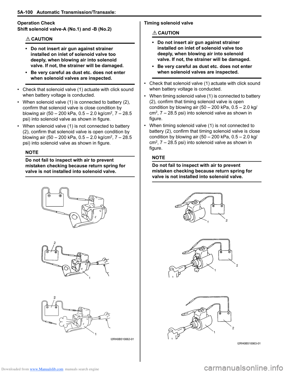
Operation Check
Shift solenoid valve-A (No.1) and -B (No.2)
CAUTION!
• Do not insert air gun against strainer installed on inlet of solenoid valve too
deeply, when blowing air into solenoid
valve. If not, the strainer will be damaged.
• Be very careful as dust etc. does not enter when solenoid valves are inspected.
• Check that solenoid valve (1) actuate with click sound when battery voltage is conducted.
• When solenoid valve (1) is connected to battery (2), confirm that solenoid valve is close condition by
blowing air (50 – 200 kPa, 0.5 – 2.0 kg/cm
2, 7 – 28.5
psi) into solenoid valve as shown in figure.
• When solenoid valve (1) is not connected to battery (2), confirm that solenoid valve is open condition by
blowing air (50 – 200 kPa, 0.5 – 2.0 kg/cm
2, 7 – 28.5
psi) into solenoid valve as shown in figure.
NOTE
Do not fail to inspect with air to prevent
mistaken checking because return spring for
valve is not installe d into solenoid valve.
Timing solenoid valve
CAUTION!
• Do not insert air gun against strainer
installed on inlet of solenoid valve too
deeply, when blowing air into solenoid
valve. If not, the strainer will be damaged.
• Be very careful as dust etc. does not enter when solenoid valves are inspected.
• Check that solenoid valve (1) actuate with click sound
when battery voltage is conducted.
• When timing solenoid valve (1 ) is connected to battery
(2), confirm that timing solenoid valve is open
condition by blowing air (50 – 200 kPa, 0.5 – 2.0 kg/
cm
2, 7 – 28.5 psi) into solenoid valve as shown in
figure.
• When timing solenoid valve (1) is not connected to battery (2), confirm that timi ng solenoid valve is close
condition by blowing air (50 – 200 kPa, 0.5 – 2.0 kg/
cm
2, 7 – 28.5 psi) into solenoid valve as shown in
figure.
NOTE
Do not fail to inspect with air to prevent
mistaken checking because return spring for
valve is not installed into solenoid valve.
I2RH0B510062-01I2RH0B510063-01
Page 779 of 1496
Downloaded from www.Manualslib.com manuals search engine Automatic Transmission/Transaxle: 5A-135
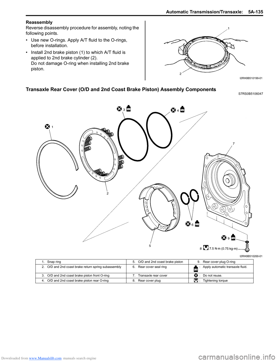
Reassembly
Reverse disassembly procedure for assembly, noting the
following points.
• Use new O-rings. Apply A/T fluid to the O-rings, before installation.
• Install 2nd brake piston (1) to which A/T fluid is applied to 2nd brake cylinder (2).
Do not damage O-ring wh en installing 2nd brake
piston.
Transaxle Rear Cover (O/D and 2nd Coast Brake Piston) Assembly ComponentsS7RS0B5106047
I2RH0B510199-01
I2RH0B510200-01
1. Snap ring 5. O/D and 2nd coast brake piston 9. Rear cover plug O-ring
2. O/D and 2nd coast brake return spring subassembly 6. R ear cover seal ring: Apply automatic transaxle fluid.
3. O/D and 2nd coast brake piston front O- ring7. Transaxle rear cover : Do not reuse.
4. O/D and 2nd coast brake piston rear O- ring8. Rear cover plug : Tightening torque
Page 796 of 1496
Downloaded from www.Manualslib.com manuals search engine 5A-152 Automatic Transmission/Transaxle:
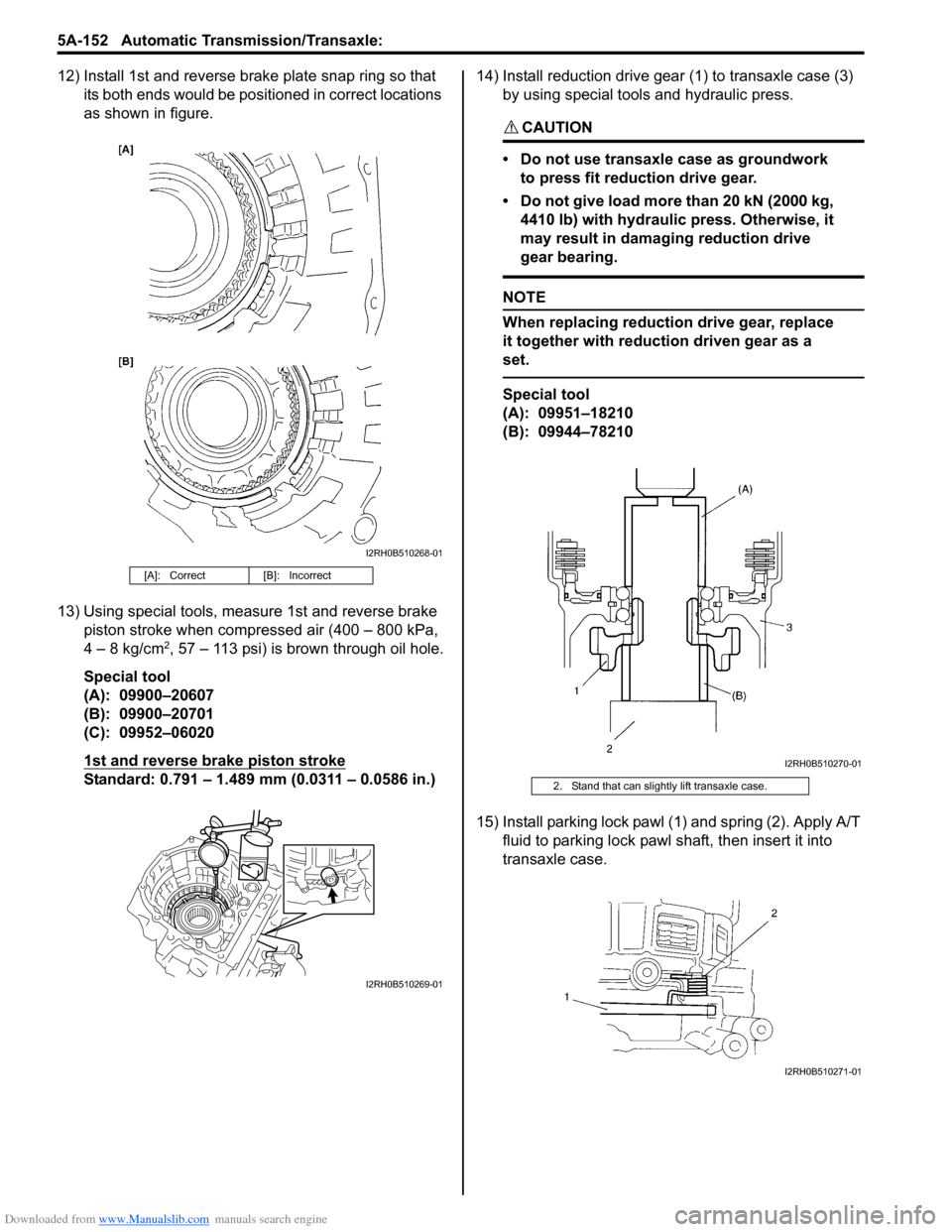
12) Install 1st and reverse brake plate snap ring so that its both ends would be positioned in correct locations
as shown in figure.
13) Using special tools, meas ure 1st and reverse brake
piston stroke when compressed air (400 – 800 kPa,
4 – 8 kg/cm
2, 57 – 113 psi) is brown through oil hole.
Special tool
(A): 09900–20607
(B): 09900–20701
(C): 09952–06020
1st and reverse brake piston stroke
Standard: 0.791 – 1.489 mm (0.0311 – 0.0586 in.) 14) Install reduction drive gear (1) to transaxle case (3)
by using special tools and hydraulic press.
CAUTION!
• Do not use transaxle case as groundwork to press fit reduction drive gear.
• Do not give load more than 20 kN (2000 kg, 4410 lb) with hydraulic press. Otherwise, it
may result in damaging reduction drive
gear bearing.
NOTE
When replacing reduction drive gear, replace
it together with reduction driven gear as a
set.
Special tool
(A): 09951–18210
(B): 09944–78210
15) Install parking lock pawl (1) and spring (2). Apply A/T fluid to parking lock pawl sh aft, then insert it into
transaxle case.
[A]: Correct [B]: Incorrect
I2RH0B510268-01
I2RH0B510269-01
2. Stand that can slightly lift transaxle case.
I2RH0B510270-01
I2RH0B510271-01
Page 797 of 1496
Downloaded from www.Manualslib.com manuals search engine Automatic Transmission/Transaxle: 5A-153
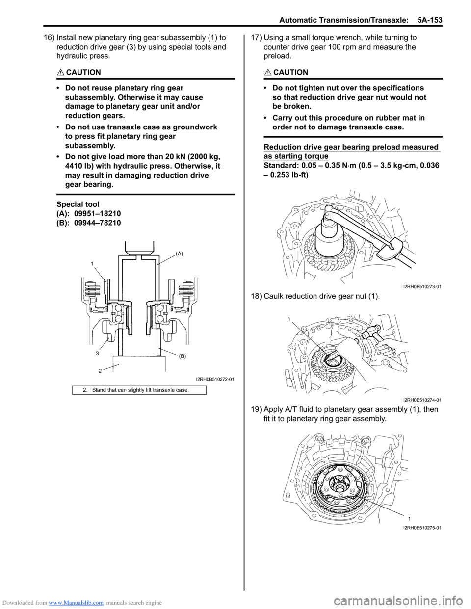
16) Install new planetary ring gear subassembly (1) to reduction drive gear (3) by using special tools and
hydraulic press.
CAUTION!
• Do not reuse planetary ring gear subassembly. Otherwise it may cause
damage to planetary gear unit and/or
reduction gears.
• Do not use transaxle case as groundwork to press fit planetary ring gear
subassembly.
• Do not give load more than 20 kN (2000 kg, 4410 lb) with hydraulic press. Otherwise, it
may result in damaging reduction drive
gear bearing.
Special tool
(A): 09951–18210
(B): 09944–78210 17) Using a small torque
wrench, while turning to
counter drive gear 100 rpm and measure the
preload.
CAUTION!
• Do not tighten nut over the specifications so that reduction drive gear nut would not
be broken.
• Carry out this procedure on rubber mat in order not to damage transaxle case.
Reduction drive gear bearing preload measured
as starting torque
Standard: 0.05 – 0.35 N ⋅m (0.5 – 3.5 kg-cm, 0.036
– 0.253 lb-ft)
18) Caulk reduction drive gear nut (1).
19) Apply A/T fluid to planetary gear assembly (1), then fit it to planetary ring gear assembly.
2. Stand that can slightly lift transaxle case.
I2RH0B510272-01
I2RH0B510273-01
I2RH0B510274-01
1
I2RH0B510275-01
Page 816 of 1496
Downloaded from www.Manualslib.com manuals search engine 5B-2 Manual Transmission/Transaxle:
I6RS0C520009-01
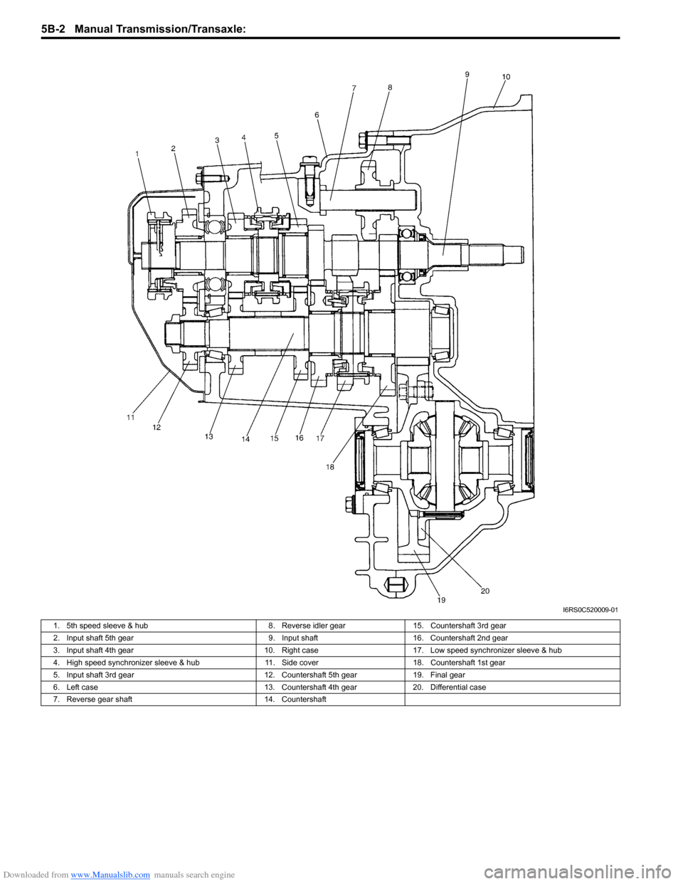
1. 5th speed sleeve & hub8. Reverse idler gear15. Countershaft 3rd gear
2. Input shaft 5th gear 9. Input shaft16. Countershaft 2nd gear
3. Input shaft 4th gear 10. Right case17. Low speed synchronizer sleeve & hub
4. High speed synchronizer sleeve & hub 11. Side cover 18. Countershaft 1st gear
5. Input shaft 3rd gear 12. Countershaft 5th gear19. Final gear
6. Left case 13. Countershaft 4th gear20. Differential case
7. Reverse gear shaft 14. Countershaft
Page 818 of 1496
Downloaded from www.Manualslib.com manuals search engine 5B-4 Manual Transmission/Transaxle:
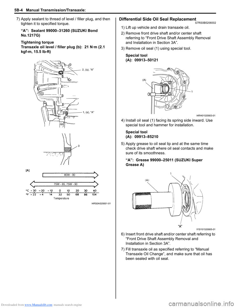
7) Apply sealant to thread of level / filler plug, and then
tighten it to specified torque.
“A”: Sealant 99000–31260 (SUZUKI Bond
No.1217G)
Tightening torque
Transaxle oil level / filler plug (b): 21 N·m (2.1
kgf-m, 15.5 lb-ft)Differential Side Oil Seal ReplacementS7RS0B5206002
1) Lift up vehicle and drain transaxle oil.
2) Remove front drive shaft and/or center shaft referring to “Front Driv e Shaft Assembly Removal
and Installation in Section 3A”.
3) Remove oil seal (1) using special tool.
Special tool
(A): 09913–50121
4) Install oil seal (1) facing its spring side inward. Use special tool and hammer for installation.
Special tool
(A): 09913–85210
5) Apply grease to oil seal lip and at the same time check drive shaft where oil seal contacts and make
sure of its smoothness.
“A”: Grease 99000–25011 (SUZUKI Super
Grease A)
6) Insert front drive shaft and/or center shaft referring to “Front Drive Shaft A ssembly Removal and
Installation in Section 3A”.
7) Fill transaxle oil as specified referring to “Manual Transaxle Oil Change”, and make sure that oil has
been sealed with oil seal.
I4RS0A520001-01
(A)
1
I4RH01520003-01
IYSY01520005-01
Page 820 of 1496
Downloaded from www.Manualslib.com manuals search engine 5B-6 Manual Transmission/Transaxle:
Gear Shift Control Lever and Cable Removal
and Installation
S7RS0B5206004
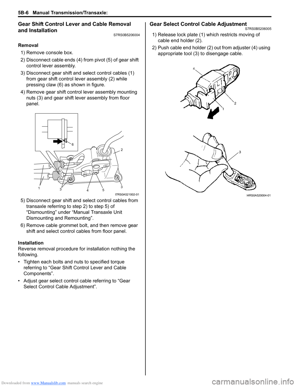
Removal1) Remove console box.
2) Disconnect cable ends (4) from pivot (5) of gear shift control lever assembly.
3) Disconnect gear shift and select control cables (1) from gear shift control lever assembly (2) while
pressing claw (6) as shown in figure.
4) Remove gear shift control lever assembly mounting nuts (3) and gear shift lever assembly from floor
panel.
5) Disconnect gear shift and select control cables from transaxle referring to step 2) to step 5) of
“Dismounting” under “Manual Transaxle Unit
Dismounting and Remounting”.
6) Remove cable grommet bolt, and then remove gear shift and select control cables from floor panel.
Installation
Reverse removal procedure for installation nothing the
following.
• Tighten each bolts and nuts to specified torque referring to “Gear Shift Control Lever and Cable
Components”.
• Adjust gear select control cable referring to “Gear Select Control Cable Adjustment”.
Gear Select Control Cable AdjustmentS7RS0B5206005
1) Release lock plate (1) which restricts moving of cable end holder (2).
2) Push cable end holder (2) out from adjuster (4) using appropriate tool (3) to disengage cable.
35
4
2
31
6
I7RS0A521002-01I4RS0A520004-01