High voltage SUZUKI SWIFT 2006 2.G Service Manual Online
[x] Cancel search | Manufacturer: SUZUKI, Model Year: 2006, Model line: SWIFT, Model: SUZUKI SWIFT 2006 2.GPages: 1496, PDF Size: 34.44 MB
Page 233 of 1496
Downloaded from www.Manualslib.com manuals search engine Engine General Information and Diagnosis: 1A-183
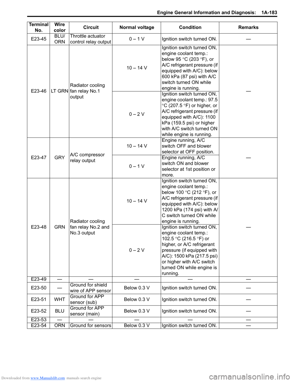
E23-45BLU/
ORNThrottle actuator
control relay output
0 – 1 V Ignition switch turned ON. —
E23-46 LT GRN Radiator cooling
fan relay No.1
output 10 – 14 V
Ignition switch turned ON,
engine coolant temp.:
below 95
°C (203 ° F), or
A/C refrigerant pressure (if
equipped with A/C): below
600 kPa (87 psi) with A/C
switch turned ON while
engine is running. —
0 – 2 V Ignition switch turned ON,
engine coolant temp.: 97.5
°
C (207.5 ° F) or higher, or
A/C refrigerant pressure (if
equipped with A/C): 1100
kPa (159.5 psi) or higher
with A/C switch turned ON
while engine is running.
E23-47 GRY A/C compressor
relay output 10 – 14 V
Engine running, A/C
switch OFF and blower
selector at OFF position.
—
0 – 1 V Engine running, A/C
switch ON and blower
selector at 1st position or
more.
E23-48 GRN Radiator cooling
fan relay No.2 and
No.3 output 10 – 14 V
Ignition switch turned ON,
engine coolant temp.:
below 100
°C (212 °F), or
A/C refrigerant pressure (if
equipped with A/C): below
1200 kPa (174 psi) with A/
C switch turned ON while
engine is running. —
0 – 2 V Ignition switch turned ON,
engine coolant temp.:
102.5
°C (216.5 °F) or
higher, or A/C refrigerant
pressure (if equipped with
A/C): 1500 kPa (217.5 psi)
or higher with A/C switch
turned ON while engine is
running.
E23-49 — — — — —
E23-50 — Ground for shield
wire of APP sensor Below 0.3 V Ignition switch turned ON. —
E23-51 WHT Ground for APP
sensor (sub) Below 0.3 V Ignition switch turned ON. —
E23-52 BLU Ground for APP
sensor (main) Below 0.3 V Ignition switch turned ON. —
E23-53 — — — — —
E23-54 ORN Ground for sensors Below 0.3 V Ignition switch turned ON. —
Terminal
No. Wire
color Circuit Normal voltage Condition Remarks
Page 246 of 1496
Downloaded from www.Manualslib.com manuals search engine 1A-196 Engine General Information and Diagnosis:
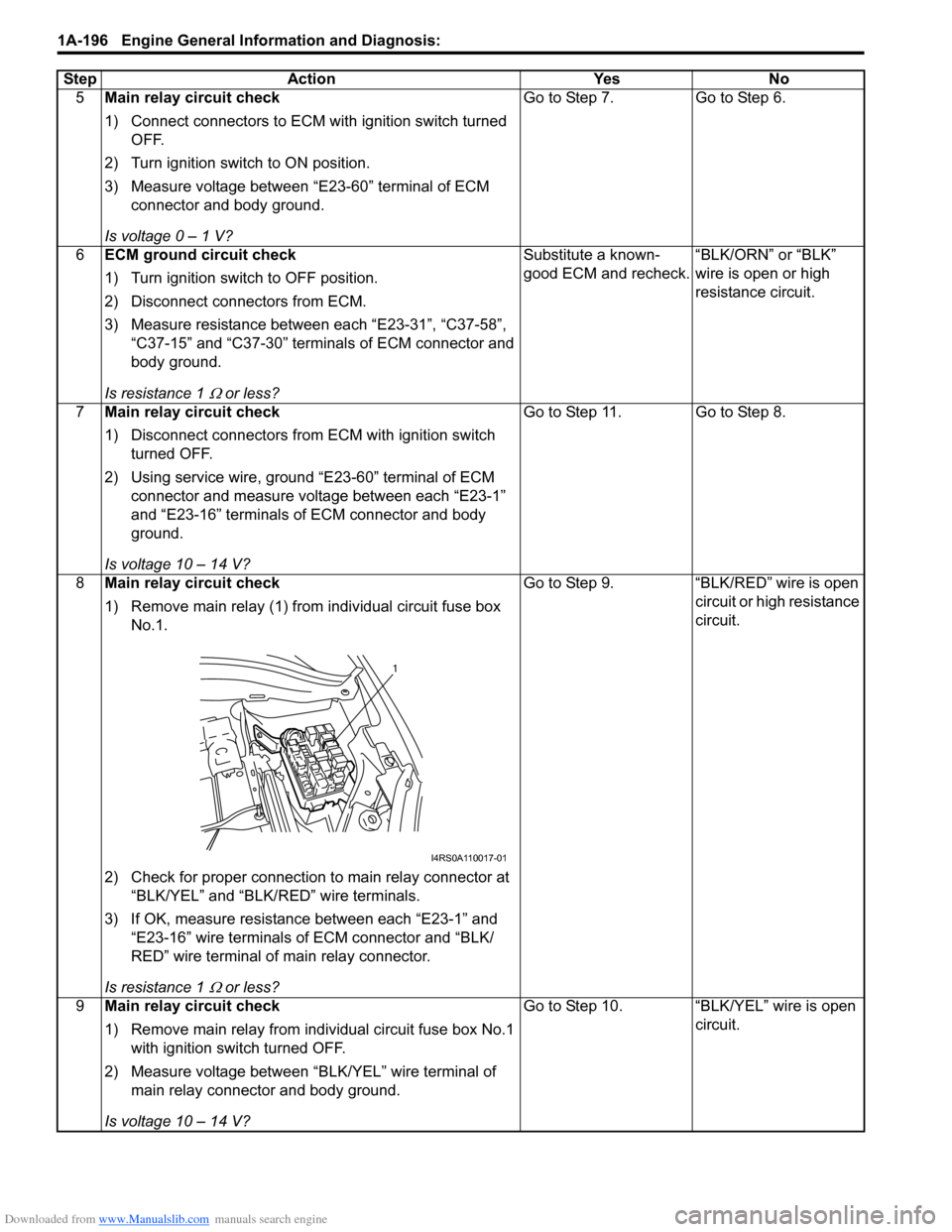
5Main relay circuit check
1) Connect connectors to ECM with ignition switch turned
OFF.
2) Turn ignition switch to ON position.
3) Measure voltage between “E23-60” terminal of ECM connector and body ground.
Is voltage 0 – 1 V? Go to Step 7. Go to Step 6.
6 ECM ground circuit check
1) Turn ignition switch to OFF position.
2) Disconnect connectors from ECM.
3) Measure resistance between each “E23-31”, “C37-58”,
“C37-15” and “C37-30” terminals of ECM connector and
body ground.
Is resistance 1
Ω or less? Substitute a known-
good ECM and recheck.
“BLK/ORN” or “BLK”
wire is open or high
resistance circuit.
7 Main relay circuit check
1) Disconnect connectors from ECM with ignition switch
turned OFF.
2) Using service wire, ground “E23-60” terminal of ECM connector and measure voltage between each “E23-1”
and “E23-16” terminals of ECM connector and body
ground.
Is voltage 10 – 14 V? Go to Step 11. Go to Step 8.
8 Main relay circuit check
1) Remove main relay (1) from individual circuit fuse box
No.1.
2) Check for proper connection to main relay connector at “BLK/YEL” and “BLK/RED” wire terminals.
3) If OK, measure resistance between each “E23-1” and “E23-16” wire terminals of ECM connector and “BLK/
RED” wire terminal of main relay connector.
Is resistance 1
Ω or less? Go to Step 9. “BLK/RED” wire is open
circuit or high resistance
circuit.
9 Main relay circuit check
1) Remove main relay from individual circuit fuse box No.1
with ignition swit ch turned OFF.
2) Measure voltage between “BLK/YEL” wire terminal of main relay connector and body ground.
Is voltage 10 – 14 V? Go to Step 10. “BLK/YEL” wire is open
circuit.
Step Action Yes No
1
I4RS0A110017-01
Page 247 of 1496
Downloaded from www.Manualslib.com manuals search engine Engine General Information and Diagnosis: 1A-197
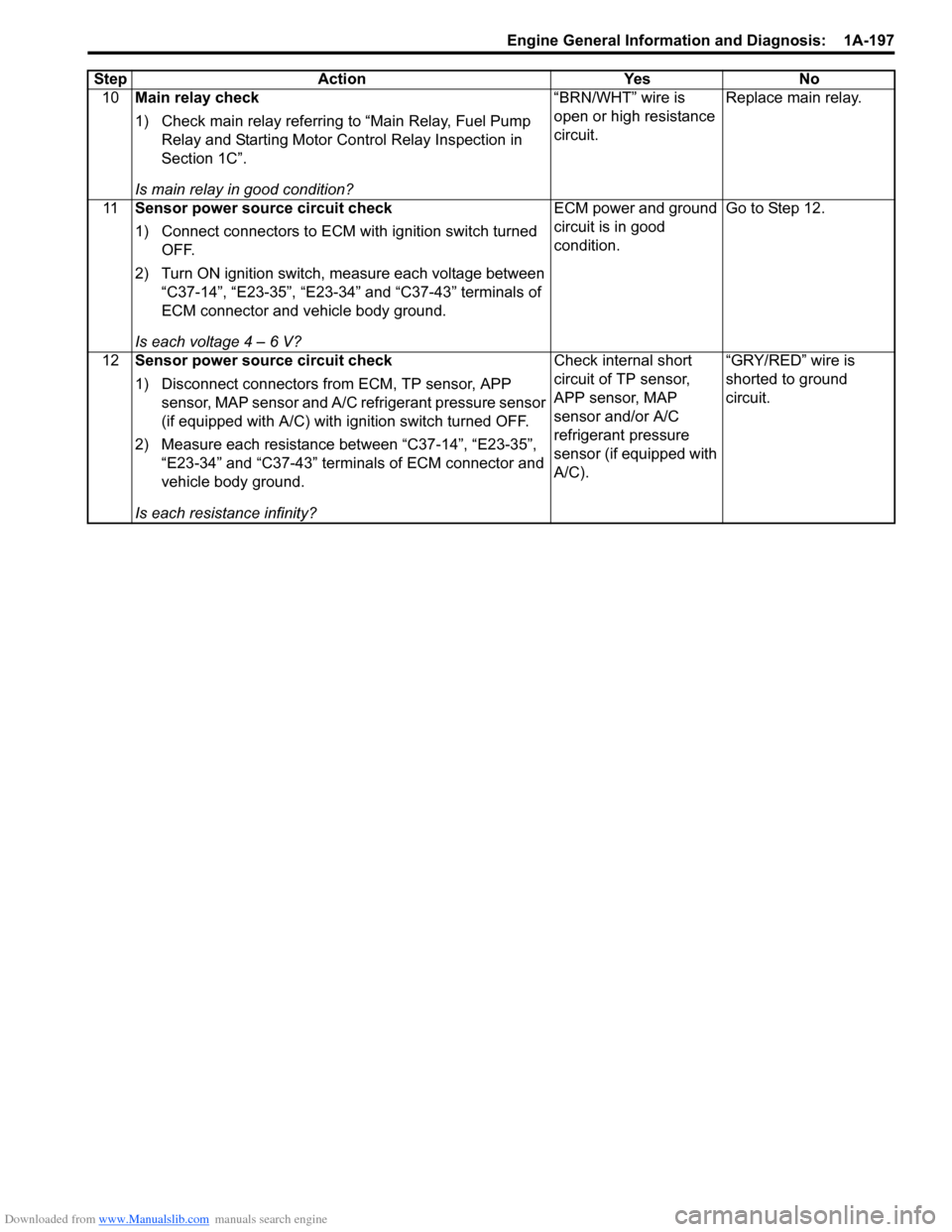
10Main relay check
1) Check main relay referring to “Main Relay, Fuel Pump
Relay and Starting Motor Control Relay Inspection in
Section 1C”.
Is main relay in good condition? “BRN/WHT” wire is
open or high resistance
circuit.
Replace main relay.
11 Sensor power source circuit check
1) Connect connectors to ECM with ignition switch turned
OFF.
2) Turn ON ignition switch, measure each voltage between “C37-14”, “E23-35”, “E23-34” and “C37-43” terminals of
ECM connector and vehicle body ground.
Is each voltage 4 – 6 V? ECM power and ground
circuit is in good
condition.
Go to Step 12.
12 Sensor power source circuit check
1) Disconnect connectors from ECM, TP sensor, APP
sensor, MAP sensor and A/C refrigerant pressure sensor
(if equipped with A/C) with i gnition switch turned OFF.
2) Measure each resistance between “C37-14”, “E23-35”, “E23-34” and “C37-43” terminals of ECM connector and
vehicle body ground.
Is each resistance infinity? Check internal short
circuit of TP sensor,
APP sensor, MAP
sensor and/or A/C
refrigerant pressure
sensor (if equipped with
A/C).
“GRY/RED” wire is
shorted to ground
circuit.
Step Action Yes No
Page 254 of 1496
Downloaded from www.Manualslib.com manuals search engine 1A-204 Engine General Information and Diagnosis:
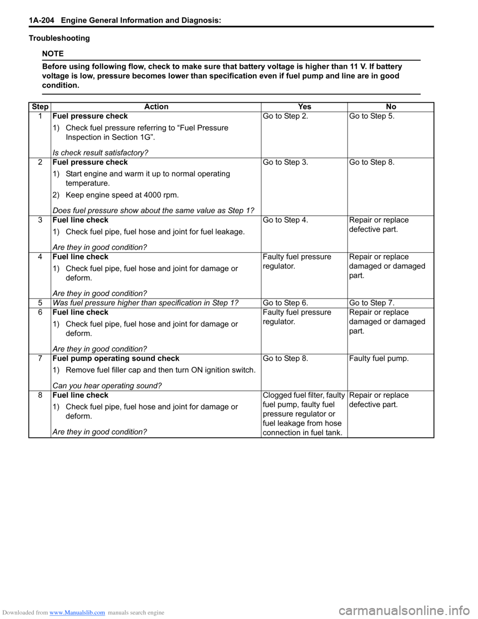
Troubleshooting
NOTE
Before using following flow, check to make sure that battery voltage is higher than 11 V. If battery
voltage is low, pressure becomes lower than specification even if fuel pump and line are in good
condition.
StepAction YesNo
1 Fuel pressure check
1) Check fuel pressure referring to “Fuel Pressure
Inspection in Section 1G”.
Is check result satisfactory? Go to Step 2.
Go to Step 5.
2 Fuel pressure check
1) Start engine and warm it up to normal operating
temperature.
2) Keep engine speed at 4000 rpm.
Does fuel pressure show about the same value as Step 1? Go to Step 3.
Go to Step 8.
3 Fuel line check
1) Check fuel pipe, fuel hose and joint for fuel leakage.
Are they in good condition? Go to Step 4.
Repair or replace
defective part.
4 Fuel line check
1) Check fuel pipe, fuel hose and joint for damage or
deform.
Are they in good condition? Faulty fuel pressure
regulator.
Repair or replace
damaged or damaged
part.
5 Was fuel pressure higher than specification in Step 1? Go to Step 6.Go to Step 7.
6 Fuel line check
1) Check fuel pipe, fuel hose and joint for damage or
deform.
Are they in good condition? Faulty fuel pressure
regulator.
Repair or replace
damaged or damaged
part.
7 Fuel pump operating sound check
1) Remove fuel filler cap and th en turn ON ignition switch.
Can you hear operating sound? Go to Step 8.
Faulty fuel pump.
8 Fuel line check
1) Check fuel pipe, fuel hose and joint for damage or
deform.
Are they in good condition? Clogged fuel filter, faulty
fuel pump, faulty fuel
pressure regulator or
fuel leakage from hose
connection in fuel tank.Repair or replace
defective part.
Page 262 of 1496
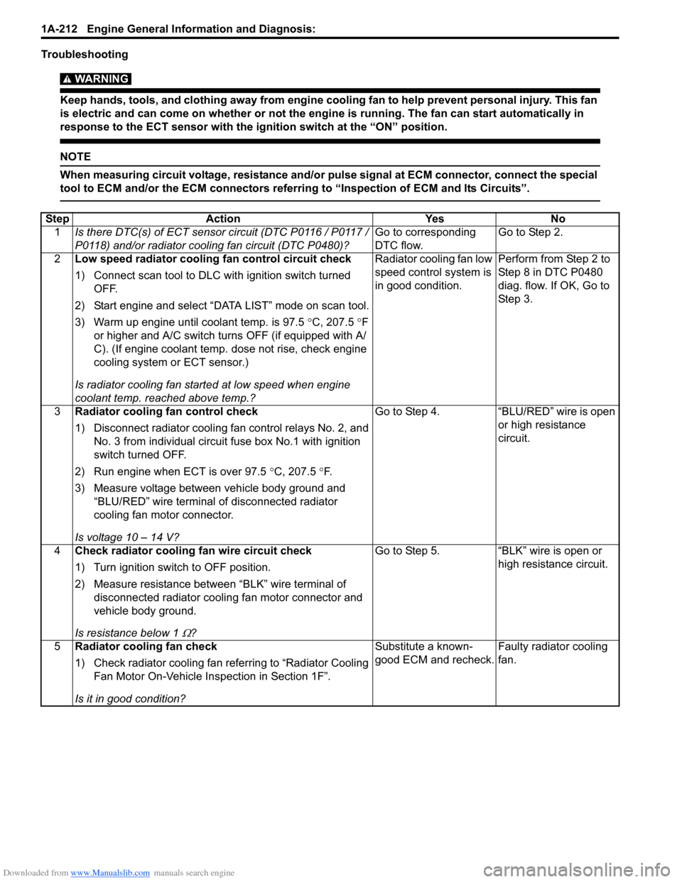
Downloaded from www.Manualslib.com manuals search engine 1A-212 Engine General Information and Diagnosis:
Troubleshooting
WARNING!
Keep hands, tools, and clothing away from engine cooling fan to help prevent personal injury. This fan
is electric and can come on whether or not the engi ne is running. The fan can start automatically in
response to the ECT sensor with the ig nition switch at the “ON” position.
NOTE
When measuring circuit voltage, resistance and/or pulse signal at ECM connector, connect the special
tool to ECM and/or the ECM connectors referri ng to “Inspection of ECM and Its Circuits”.
StepAction YesNo
1 Is there DTC(s) of ECT sensor circuit (DTC P0116 / P0117 /
P0118) and/or radiator cooling fan circuit (DTC P0480)? Go to corresponding
DTC flow.Go to Step 2.
2 Low speed radiator cooling fan control circuit check
1) Connect scan tool to DLC with ignition switch turned
OFF.
2) Start engine and select “DATA LIST” mode on scan tool.
3) Warm up engine until coolant temp. is 97.5 °C, 207.5 °F
or higher and A/C switch turns OFF (if equipped with A/
C). (If engine coolant temp. dose not rise, check engine
cooling system or ECT sensor.)
Is radiator cooling fan started at low speed when engine
coolant temp. reached above temp.? Radiator cooling fan low
speed control system is
in good condition.
Perform from Step 2 to
Step 8 in DTC P0480
diag. flow. If OK, Go to
Ste p 3.
3 Radiator cooling fan control check
1) Disconnect radiator cooling fan control relays No. 2, and
No. 3 from individual circuit fuse box No.1 with ignition
switch turned OFF.
2) Run engine when ECT is over 97.5 °C, 207.5 °F.
3) Measure voltage between vehicle body ground and “BLU/RED” wire terminal of disconnected radiator
cooling fan motor connector.
Is voltage 10 – 14 V? Go to Step 4.
“BLU/RED” wire is open
or high resistance
circuit.
4 Check radiator cooling fan wire circuit check
1) Turn ignition switch to OFF position.
2) Measure resistance between “BLK” wire terminal of
disconnected radiator coolin g fan motor connector and
vehicle body ground.
Is resistance below 1
Ω? Go to Step 5. “BLK” wire is open or
high resistance circuit.
5 Radiator cooling fan check
1) Check radiator cooling fan referring to “Radiator Cooling
Fan Motor On-Vehicle Inspection in Section 1F”.
Is it in good condition? Substitute a known-
good ECM and recheck.
Faulty radiator cooling
fan.
Page 264 of 1496
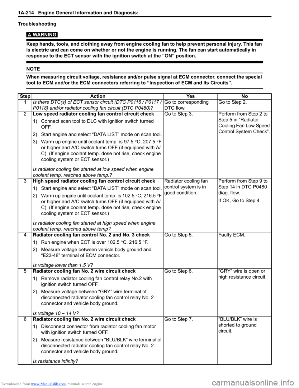
Downloaded from www.Manualslib.com manuals search engine 1A-214 Engine General Information and Diagnosis:
Troubleshooting
WARNING!
Keep hands, tools, and clothing away from engine cooling fan to help prevent personal injury. This fan
is electric and can come on whether or not the engi ne is running. The fan can start automatically in
response to the ECT sensor with the ig nition switch at the “ON” position.
NOTE
When measuring circuit voltage, resistance and/or pulse signal at ECM connector, connect the special
tool to ECM and/or the ECM connectors referri ng to “Inspection of ECM and Its Circuits”.
StepAction YesNo
1 Is there DTC(s) of ECT sensor circuit (DTC P0116 / P0117 /
P0118) and/or radiator cooling fan circuit (DTC P0480)? Go to corresponding
DTC flow.Go to Step 2.
2 Low speed radiator cooling fan control circuit check
1) Connect scan tool to DLC with ignition switch turned
OFF.
2) Start engine and select “DATA LIST” mode on scan tool.
3) Warm up engine until coolant temp. is 97.5 °C, 207.5 °F
or higher and A/C switch turns OFF (if equipped with A/
C). (If engine coolant temp. dose not rise, check engine
cooling system or ECT sensor.)
Is radiator cooling fan started at low speed when engine
coolant temp. reached above temp.? Go to Step 3.
Perform from Step 2 to
Step 5 in “Radiator
Cooling Fan Low Speed
Control System Check”.
3 High speed radiator cooling fan control circuit check
1) Start engine and select “DATA LIST” mode on scan tool.
2) Warm up engine until coolant temp. is 102.5 °C, 216.5 °F
or higher and A/C switch turns OFF (if equipped with A/
C). (If engine coolant temp. dose not rise, check engine
cooling system or ECT sensor.)
Is radiator cooling fan started at high speed when engine
coolant temp. reached above temp? Radiator cooling fan
control system is in
good condition.
Perform from Step 9 to
Step 14 in DTC P0480
diag. flow.
If OK, Go to Step 4.
4 Radiator cooling fan control No. 2 and No. 3 check
1) Run engine when ECT is over 102.5 °C, 216.5 °F.
2) Measure voltage between vehicle body ground and “E23-48” terminal of ECM connector.
Is voltage lower than 1.5 V? Go to Step 5.
Faulty ECM.
5 Radiator cooling fan No. 2 wire circuit check
1) Remove radiator cooling fan control relay No.2 with
ignition switch turned OFF.
2) Measure voltage between “GRY” wire terminal of disconnected radiator cooling fan control relay No. 2
connector and vehicle body ground.
Is voltage 10 – 14 V? Go to Step 6.
“GRY” wire is open or
high resistance circuit.
6 Radiator cooling fan No. 2 wire circuit check
1) Disconnect connector from radiator cooling fan motor
with ignition swit ch turned OFF.
2) Measure resistance between “BLU/BLK” wire terminal of disconnected radiator cooling fan control relay No. 2
connector and vehicle body ground.
Is resistance infinity? Go to Step 7.
“BLU/BLK” wire is
shorted to ground
circuit.
Page 265 of 1496
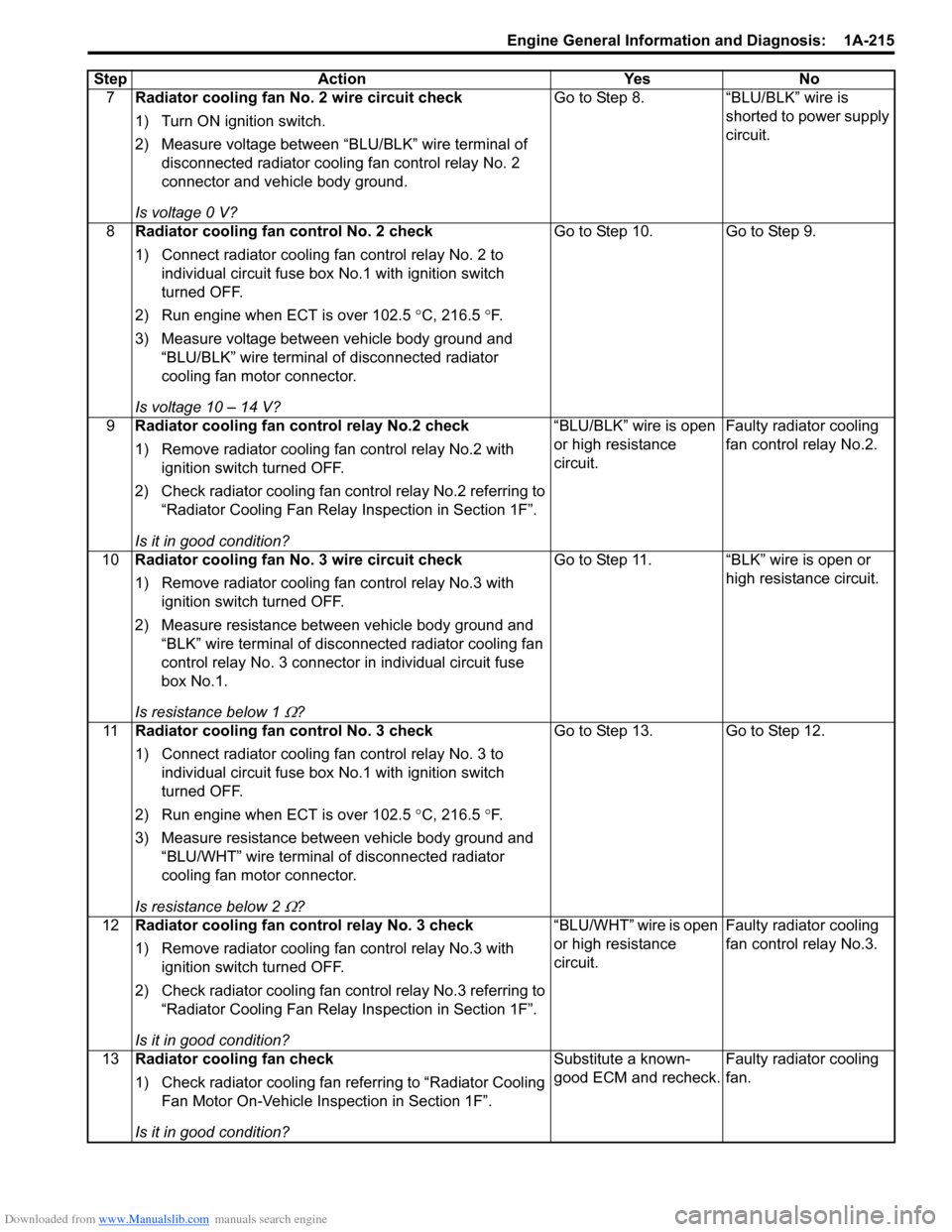
Downloaded from www.Manualslib.com manuals search engine Engine General Information and Diagnosis: 1A-215
7Radiator cooling fan No. 2 wire circuit check
1) Turn ON ignition switch.
2) Measure voltage between “BLU/BLK” wire terminal of
disconnected radiator cooling fan control relay No. 2
connector and vehicle body ground.
Is voltage 0 V? Go to Step 8. “BLU/BLK” wire is
shorted to power supply
circuit.
8 Radiator cooling fan control No. 2 check
1) Connect radiator cooling fan control relay No. 2 to
individual circuit fuse box No.1 with ignition switch
turned OFF.
2) Run engine when ECT is over 102.5 °C, 216.5 °F.
3) Measure voltage between vehicle body ground and “BLU/BLK” wire terminal of disconnected radiator
cooling fan motor connector.
Is voltage 10 – 14 V? Go to Step 10. Go to Step 9.
9 Radiator cooling fan control relay No.2 check
1) Remove radiator cooling fan control relay No.2 with
ignition switch turned OFF.
2) Check radiator cooling fan control relay No.2 referring to “Radiator Cooling Fan Relay Inspection in Section 1F”.
Is it in good condition? “BLU/BLK” wire is open
or high resistance
circuit.
Faulty radiator cooling
fan control relay No.2.
10 Radiator cooling fan No. 3 wire circuit check
1) Remove radiator cooling fan control relay No.3 with
ignition switch turned OFF.
2) Measure resistance between vehicle body ground and “BLK” wire terminal of disconnected radiator cooling fan
control relay No. 3 connector in individual circuit fuse
box No.1.
Is resistance below 1
Ω? Go to Step 11. “BLK” wire is open or
high resistance circuit.
11 Radiator cooling fan control No. 3 check
1) Connect radiator cooling fan control relay No. 3 to
individual circuit fuse box No.1 with ignition switch
turned OFF.
2) Run engine when ECT is over 102.5 °C, 216.5 °F.
3) Measure resistance between vehicle body ground and “BLU/WHT” wire terminal of disconnected radiator
cooling fan motor connector.
Is resistance below 2
Ω? Go to Step 13. Go to Step 12.
12 Radiator cooling fan control relay No. 3 check
1) Remove radiator cooling fan control relay No.3 with
ignition switch turned OFF.
2) Check radiator cooling fan control relay No.3 referring to “Radiator Cooling Fan Relay Inspection in Section 1F”.
Is it in good condition? “BLU/WHT” wire is open
or high resistance
circuit.
Faulty radiator cooling
fan control relay No.3.
13 Radiator cooling fan check
1) Check radiator cooling fan referring to “Radiator Cooling
Fan Motor On-Vehicle Inspection in Section 1F”.
Is it in good condition? Substitute a known-
good ECM and recheck.
Faulty radiator cooling
fan.
Step
Action YesNo
Page 378 of 1496
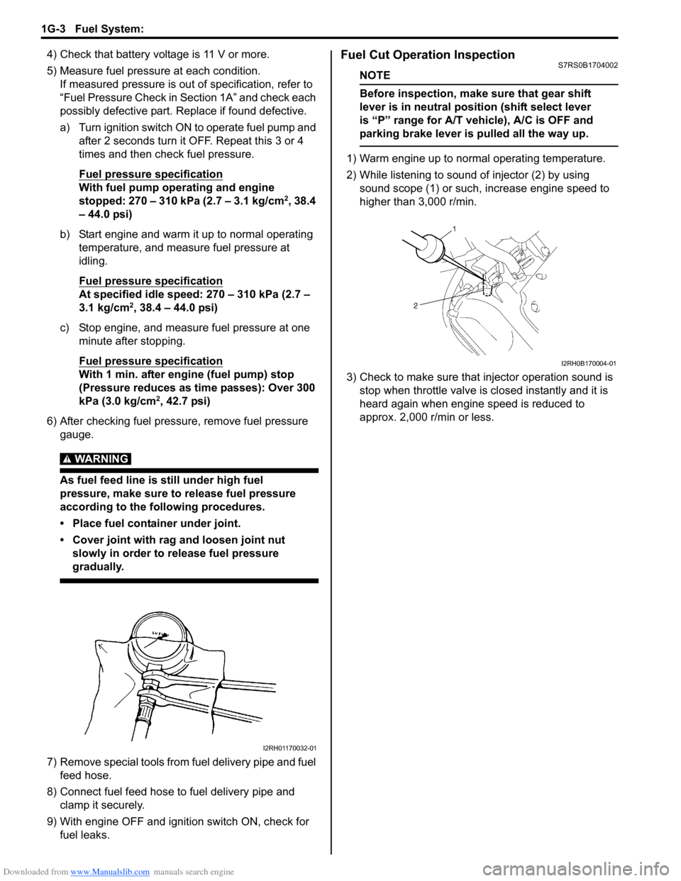
Downloaded from www.Manualslib.com manuals search engine 1G-3 Fuel System:
4) Check that battery voltage is 11 V or more.
5) Measure fuel pressure at each condition.If measured pressure is out of specification, refer to
“Fuel Pressure Check in Section 1A” and check each
possibly defective part. Replace if found defective.
a) Turn ignition switch ON to operate fuel pump and after 2 seconds turn it OFF. Repeat this 3 or 4
times and then check fuel pressure.
Fuel pressure specification
With fuel pump operating and engine
stopped: 270 – 310 kPa (2.7 – 3.1 kg/cm2, 38.4
– 44.0 psi)
b) Start engine and warm it up to normal operating temperature, and measure fuel pressure at
idling.
Fuel pressure specification
At specified idle speed: 270 – 310 kPa (2.7 –
3.1 kg/cm2, 38.4 – 44.0 psi)
c) Stop engine, and measure fuel pressure at one minute after stopping.
Fuel pressure specification
With 1 min. after engine (fuel pump) stop
(Pressure reduces as time passes): Over 300
kPa (3.0 kg/cm
2, 42.7 psi)
6) After checking fuel pressure, remove fuel pressure gauge.
WARNING!
As fuel feed line is still under high fuel
pressure, make sure to release fuel pressure
according to the following procedures.
• Place fuel container under joint.
• Cover joint with rag and loosen joint nut slowly in order to release fuel pressure
gradually.
7) Remove special tools from fuel delivery pipe and fuel feed hose.
8) Connect fuel feed hose to fuel delivery pipe and clamp it securely.
9) With engine OFF and ignition switch ON, check for fuel leaks.
Fuel Cut Operation InspectionS7RS0B1704002
NOTE
Before inspection, make sure that gear shift
lever is in neutral positi on (shift select lever
is “P” range for A/T vehicle), A/C is OFF and
parking brake lever is pulled all the way up.
1) Warm engine up to normal operating temperature.
2) While listening to sound of injector (2) by using sound scope (1) or such, increase engine speed to
higher than 3,000 r/min.
3) Check to make sure that injector operation sound is stop when throttle valve is closed instantly and it is
heard again when engine speed is reduced to
approx. 2,000 r/min or less.
I2RH01170032-01
I2RH0B170004-01
Page 393 of 1496
Downloaded from www.Manualslib.com manuals search engine Ignition System: 1H-1
Engine
Ignition System
General Description
Ignition System ConstructionS7RS0B1801001
The ignition system is an electronic (distributorless) ignition system. It consists of the parts as described below.
• ECM
It detects the engine and vehicle conditions through the si gnals from the sensors, determines the most suitable
ignition timing and time for electricity to flow to the primar y coil and sends a signal to the ignitor (power unit) in the
ignition coil assembly.
• Ignition coil assembly (including an ignitor)
The ignition coil assembly has a built -in ignitor which turns ON and OFF the current flow to the primary coil
according to the signal from ECM. When the current flow to the primary coil is turned OFF, a high voltage is induced
in the secondary coil.
• High-tension cords and spark plugs
• CMP sensor (Camshaft position sensor) and CKP sensor (Crankshaft position sensor)
Using signals from these sensors, ECM identifies the specific cylinder whose piston is in the compression stroke,
detects the crank angle and adjusts in itial ignition timing automatically.
• TP sensor, ECT sensor, MAP sensor, MAF sensor, IAT sensor, knock sensor and other sensors / switches
Although this ignition system does not have a distributor, it has two ignition coil assemblies (one is for No.1 and No.4
spark plugs and the other is for No.2 and No.3 spark plugs). W hen an ignition signal is sent from ECM to the ignitor in
the ignition coil assembly for No.1 and No.4 spark plugs, a high voltage is induced in the secondary coil and that
passes through the high-tension cords and causes No.1 and No.4 spark plugs to spark simultaneously. Likewise,
when an ignition signal is sent to the ignitor in the ot her ignition coil assembly, No.2 and No.3 spark plugs spark
simultaneously.
Page 411 of 1496
Downloaded from www.Manualslib.com manuals search engine Charging System: 1J-1
Engine
Charging System
General Description
Battery DescriptionS7RS0B1A01001
The battery has three major functions in the electrical
system.
• It is a source of electrical energy for cranking the engine.
• It acts as a voltage stabilizer for the electrical system.
• It can, for a limited time, provide energy when the electrical load exceeds the output of the generator.
Carrier and Hold-Down
The battery carrier should be in good condition so that it
will support the battery securely and keep it level. Before
installing the battery, the ba ttery carrier and hold-down
clamp should be clean and free from corrosion and
make certain there are no parts in carrier.
To prevent the battery from shaking in its carrier, the
hold-down bolts should be tight enough but not over-
tightened.
Electrolyte Freezing
The freezing point of electrolyte depends on its specific
gravity. Since freezing may ruin a battery, it should be
protected against freezing by keeping it in a fully
charged condition. If a battery is frozen accidentally, it
should not be charged until it is warmed.
Sulfation
If the battery is allowed to stand for a long period in
discharged condition, the lead sulfate becomes
converted into a hard, cryst alline substance, which will
not easily turn back to the active material again during
the subsequent recharging. “Sulfation” means the result
as well as the process of that reaction. Such a battery
can be revived by very slow charging and may be
restored to usable condition but its capacity is lower than
before. Built-In Indicator (If Equipped)
The battery has a built-in temperature compensated
indicator in the top of the battery. This indicator is to be
used with the following diagnostic procedure. When
checking the indicator, make sure that the battery has a
clean top. A light may be needed in some poorly-lit
areas.
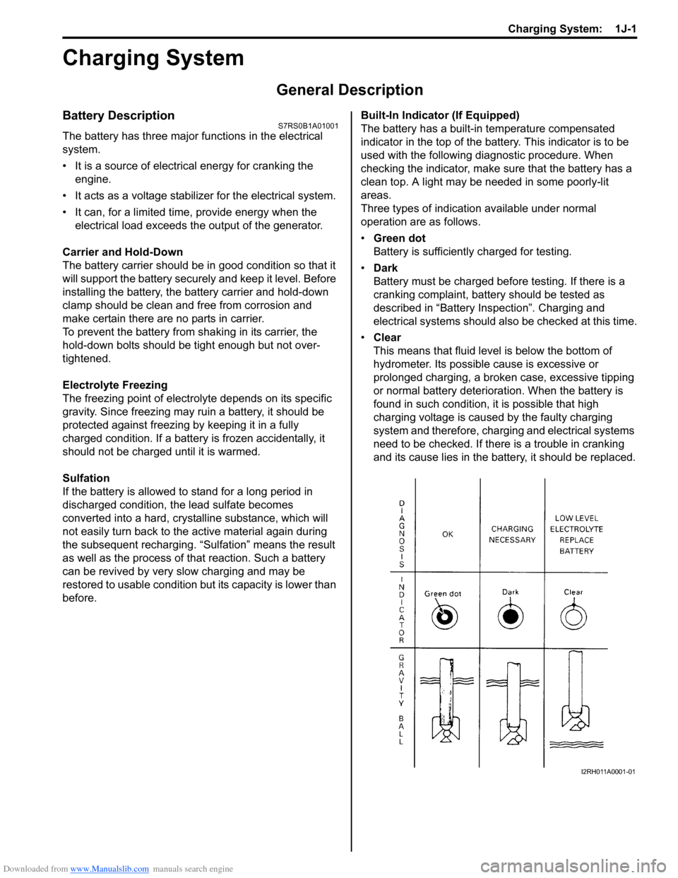
Three types of indication available under normal
operation are as follows.
•
Green dot
Battery is sufficiently charged for testing.
• Dark
Battery must be charged before testing. If there is a
cranking complaint, battery should be tested as
described in “Battery Inspection”. Charging and
electrical systems should also be checked at this time.
• Clear
This means that fluid level is below the bottom of
hydrometer. Its possible cause is excessive or
prolonged charging, a broken case, excessive tipping
or normal battery deteriorat ion. When the battery is
found in such condition, it is possible that high
charging voltage is caused by the faulty charging
system and therefore, charging and electrical systems
need to be checked. If there is a trouble in cranking
and its cause lies in the battery, it should be replaced.
I2RH011A0001-01