6C-16 SUZUKI SWIFT 2006 2.G Service Workshop Manual
[x] Cancel search | Manufacturer: SUZUKI, Model Year: 2006, Model line: SWIFT, Model: SUZUKI SWIFT 2006 2.GPages: 1496, PDF Size: 34.44 MB
Page 867 of 1496

Downloaded from www.Manualslib.com manuals search engine Table of Contents 6- i
6
Section 6
CONTENTS
Steering
Precautions ................................................. 6-1
Precautions............................................................. 6-1
Precautions on Steering........................................ 6-1
Steering General Diagnosi s.................... 6A-1
Precautions........................................................... 6A-1
Precautions for Steering Diagnosis ..................... 6A-1
Diagnostic Information and Procedures ............ 6A-2 Steering Symptom Diagnosis .............................. 6A-2
Steering Wheel and Column ................... 6B-1
Precautions........................................................... 6B-1
Service Precautions of Steering Wheel and Column.............................................................. 6B-1
General Description ............................................. 6B-1 Steering Wheel and Column Construction .......... 6B-1
Diagnostic Information and Procedures ............ 6B-2 Checking Steering Column for Accident Damage ............................................................ 6B-2
Repair Instructions .............................................. 6B-3 Steering Wheel and Column Construction .......... 6B-3
Steering Wheel Removal and Installation ........... 6B-4
Contact Coil Cable Assembly Removal and Installation ......................................................... 6B-5
Centering Contact Coil Cable Assembly ............. 6B-6
Contact Coil Cable Assembly Inspection ............ 6B-6
Steering Angle Sensor Removal and Installation ......................................................... 6B-6
Steering Angle Sensor Inspection ....................... 6B-6
Steering Column Removal and Installation ......... 6B-7
Steering Column Inspecti on ................................ 6B-8
Ignition Switch Cylinder Assembly Removal and Installation (Non- Keyless Start Model)...... 6B-9
Steering Lock Assembly (Ignition Switch) Removal and Installation................................... 6B-9
Steering Lower Shaft Removal and Installation ....................................................... 6B-10
Specifications ..................................................... 6B-11
Tightening Torque Specifications ...................... 6B-11
Special Tools and Equipmen t ........................... 6B-11
Special Tool ...................................................... 6B-11
Power Assisted Steering System........... 6C-1
Precautions........................................................... 6C-1 Steering System Note .........................................6C-1
Precautions in Diagnosing Troubles ...................6C-1
General Description .............................................6C-2 P/S System Description ......................................6C-2
EPS Diagnosis General Descr iption ...................6C-3
On-Board Diagnostic System Description ...........6C-3
Schematic and Routing Diagram ........................6C-4 EPS System Wiring Circuit Diagram ...................6C-4
Diagnostic Information and Procedures ............6C-5 EPS System Check .............. ...............................6C-5
“EPS” Warning Light Check . ...............................6C-8
DTC Check..........................................................6C-8
DTC Clearance ...................................................6C-9
DTC Table ...........................................................6C-9
Scan Tool Data .................................................6C-11
Visual Inspection ...............................................6C-12
P/S System Symptom Diagnosis ......................6C-12
Serial Data Link Circuit Check ..........................6C-13
“EPS” Warning Light Do es Not Come ON with
Ignition Switch Turn ed ON before Engine
Starts ...............................................................6C-15
“EPS” Warning Light Remains ON Steady after Engine Starts ..........................................6C-16
DTC C1113: Steering Torque Sensor (Main and Sub) Circuit Correlation ............................6C-17
DTC C1114: Steering Torque Sensor Reference Power Supply Circuit .....................6C-19
DTC C1117: Steering Torque Sensor Failure Signal Circuit Low ...........................................6C-21
DTC C1118: Steering Torque Sensor Failure Signal Circuit High...........................................6C-22
DTC C1119: Steering Torque Sensor Power Supply Circuit ..................................................6C-24
DTC C1121 / C1123 / C1124: VSS Circuit
Failure .............................................................6C-26
DTC C1122: Engine Speed Signal....................6C-28
DTC C1141 / C1142 / C1143 / C1145: P/S Motor Circuit Failure ........................................6C-30
DTC C1153: P/S Control Module Power Supply Circuit Voltage Low .............................6C-32
DTC C1155: P/S Control Module Failure ..........6C-33
P/S Control Module Power Supply and Ground Circuit Check ......................................6C-34
Inspection of P/S Control Module and Its Circuits ............................................................6C-35
Page 898 of 1496

Downloaded from www.Manualslib.com manuals search engine 6C-16 Power Assisted Steering System:
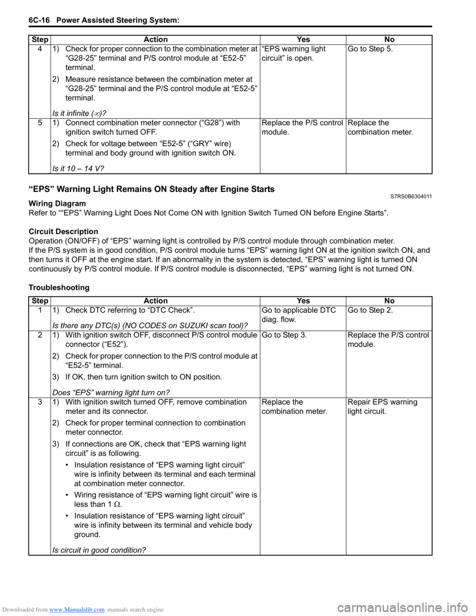
“EPS” Warning Light Remains ON Steady after Engine StartsS7RS0B6304011
Wiring Diagram
Refer to ““EPS” Warning Light Does Not Come ON with Ignition Switch Turned ON before Engine Starts”.
Circuit Description
Operation (ON/OFF) of “EPS” warning light is controlled by P/S c ontrol module through combination meter.
If the P/S system is in good condition, P/S control module tu rns “EPS” warning light ON at the ignition switch ON, and
then turns it OFF at the engine start. If an abnormality in the system is detected, “EPS” warning light is turned ON
continuously by P/S control module. If P/S control module is disconnected, “EPS” warning light is not turned ON.
Troubleshooting 4 1) Check for proper connection to the combination meter at
“G28-25” terminal and P/S control module at “E52-5”
terminal.
2) Measure resistance between the combination meter at “G28-25” terminal and the P/S control module at “E52-5”
terminal.
Is it infinite (
∞)? “EPS warning light
circuit” is open.
Go to Step 5.
5 1) Connect combination meter connector (“G28”) with ignition switch turned OFF.
2) Check for voltage between “E52-5” (“GRY” wire) terminal and body ground with ignition switch ON.
Is it 10 – 14 V? Replace the P/S control
module.
Replace the
combination meter.
Step
Action YesNo
Step Action YesNo
1 1) Check DTC referring to “DTC Check”.
Is there any DTC(s) (NO CODES on SUZUKI scan tool)? Go to applicable DTC
diag. flow.
Go to Step 2.
2 1) With ignition switch OFF, disconnect P/S control module connector (“E52”).
2) Check for proper connection to the P/S control module at “E52-5” terminal.
3) If OK, then turn ignition switch to ON position.
Does “EPS” warning light turn on? Go to Step 3.
Replace the P/S control
module.
3 1) With ignition switch turned OFF, remove combination meter and its connector.
2) Check for proper terminal connection to combination meter connector.
3) If connections are OK, ch eck that “EPS warning light
circuit” is as following.
• Insulation resistance of “EPS warning light circuit” wire is infinity between its terminal and each terminal
at combination meter connector.
• Wiring resistance of “EPS wa rning light circuit” wire is
less than 1 Ω.
• Insulation resistance of “EPS warning light circuit” wire is infinity between its terminal and vehicle body
ground.
Is circuit in good condition? Replace the
combination meter.
Repair EPS warning
light circuit.