806 SUZUKI SWIFT 2006 2.G Service Workshop Manual
[x] Cancel search | Manufacturer: SUZUKI, Model Year: 2006, Model line: SWIFT, Model: SUZUKI SWIFT 2006 2.GPages: 1496, PDF Size: 34.44 MB
Page 398 of 1496
Downloaded from www.Manualslib.com manuals search engine 1H-6 Ignition System:
Ignition Spark TestS7RS0B1804004
1) Remove air cleaner assembly with air intake pipe.
2) Disconnect all injector couplers from injectors.
WARNING!
Without disconnection of injector couplers,
combustible gas may come out from spark
plug holes during this test and may get
ignited in engine room.
3) Remove spark plug and check it for condition and
type referring to “Spark Plug Inspection”.
4) If OK, connect ignition coil coupler to ignition coil assembly and connect spark plug to ignition coil
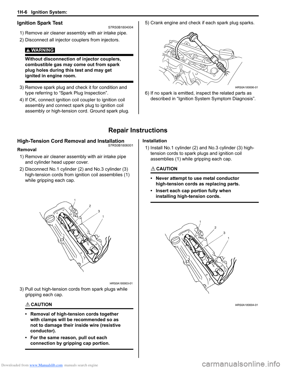
assembly or high-tension cord. Ground spark plug. 5) Crank engine and check if each spark plug sparks.
6) If no spark is emitted, inspect the related parts as
described in “Ignition System Symptom Diagnosis”.
Repair Instructions
High-Tension Cord Removal and InstallationS7RS0B1806001
Removal
1) Remove air cleaner assembly with air intake pipe and cylinder head upper cover.
2) Disconnect No.1 cylinder (2) and No.3 cylinder (3)
high-tension cords from ignition coil assemblies (1)
while gripping each cap.
3) Pull out high-tension cords from spark plugs while gripping each cap.
CAUTION!
• Removal of high-tension cords together with clamps will be recommended so as
not to damage their inside wire (resistive
conductor).
• For the same reason, pull out each connection by gripping cap portion.
Installation
1) Install No.1 cylinder (2) and No.3 cylinder (3) high-
tension cords to spark plugs and ignition coil
assemblies (1) while gripping each cap.
CAUTION!
• Never attempt to use metal conductor high-tension cords as replacing parts.
• Insert each cap portion fully when installing high-tension cords.
I4RS0A180006-01
I4RS0A180003-01
I4RS0A180004-01
Page 399 of 1496
Downloaded from www.Manualslib.com manuals search engine Ignition System: 1H-7
High-Tension Cord InspectionS7RS0B1806002
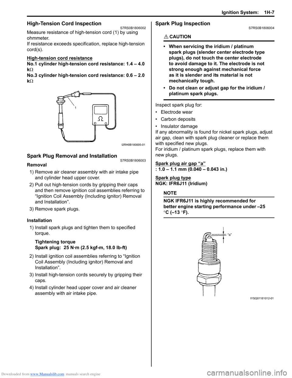
Measure resistance of high-tension cord (1) by using
ohmmeter.
If resistance exceeds specification, replace high-tension
cord(s).
High-tension cord resistance
No.1 cylinder high-tension cord resistance: 1.4 – 4.0
k Ω
No.3 cylinder high-tension cord resistance: 0.6 – 2.0
k Ω
Spark Plug Removal and InstallationS7RS0B1806003
Removal
1) Remove air cleaner assembly with air intake pipe and cylinder head upper cover.
2) Pull out high-tension cords by gripping their caps and then remove ignition coil assemblies referring to
“Ignition Coil Assembly (Inc luding ignitor) Removal
and Installation”.
3) Remove spark plugs.
Installation 1) Install spark plugs and tighten them to specified torque.
Tightening torque
Spark plug: 25 N·m (2.5 kgf-m, 18.0 lb-ft)
2) Install ignition coil assemblies referring to “Ignition Coil Assembly (Including ignitor) Removal and
Installation”.
3) Install high-tension cords securely by gripping their caps.
4) Install cylinder head upper cover and air cleaner assembly with air intake pipe.
Spark Plug InspectionS7RS0B1806004
CAUTION!
• When servicing the iridium / platinum
spark plugs (slender center electrode type
plugs), do not touch the center electrode
to avoid damage to it. The electrode is not
strong enough against mechanical force
as it is slender and its material is not
mechanically tough.
• Do not clean or adjust gap for the iridium / platinum spark plugs.
Inspect spark plug for:
• Electrode wear
• Carbon deposits
• Insulator damage
If any abnormality is found for nickel spark plugs, adjust
air gap, clean with spark plug cleaner or replace them
with specified new plugs.
For iridium / platinum spark plugs, replace them with
new plugs.
Spark plug air gap
“a”
: 1.0 – 1.1 mm (0.040 – 0.043 in.)
Spark plug type
NGK: IFR6J11 (Iridium)
NOTE
NGK IFR6J11 is highly recommended for
better engine starting performance under –25
°C (–13 °F).
I2RH0B180005-01
IYSQ01181012-01
Page 400 of 1496
Downloaded from www.Manualslib.com manuals search engine 1H-8 Ignition System:
Ignition Coil Assembly (Including ignitor)
Removal and Installation
S7RS0B1806005
Removal1) Disconnect negative (–) cable at battery.
2) Remove air cleaner assembly with air intake pipe and cylinder head upper cover.
3) Disconnect ignition coil coupler.
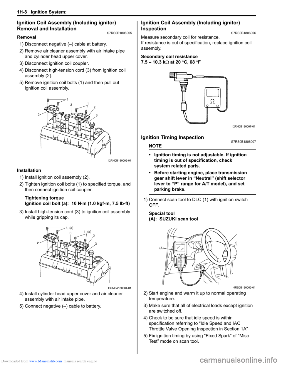
4) Disconnect high-tension cord (3) from ignition coil assembly (2).
5) Remove ignition coil bolts (1) and then pull out ignition coil assembly.
Installation 1) Install ignition coil assembly (2).
2) Tighten ignition coil bolts (1) to specified torque, and then connect igni tion coil coupler.
Tightening torque
Ignition coil bolt (a): 10 N·m (1.0 kgf-m, 7.5 lb-ft)
3) Install high-tension cord (3) to ignition coil assembly while gripping its cap.
4) Install cylinder head upper cover and air cleaner assembly with air intake pipe.
5) Connect negative (–) cable to battery.
Ignition Coil Assembly (Including ignitor)
Inspection
S7RS0B1806006
Measure secondary coil for resistance.
If resistance is out of specification, replace ignition coil
assembly.
Secondary coil resistance
7.5 – 10.3 k Ω at 20 °C, 68 ° F
Ignition Timing InspectionS7RS0B1806007
NOTE
• Ignition timing is not adjustable. If ignition
timing is out of specification, check
system related parts.
• Before starting engine, place transmission gear shift lever in “Neutral” (shift selector
lever to “P” range for A/T model), and set
parking brake.
1) Connect scan tool to DLC (1) with ignition switch OFF.
Special tool
(A): SUZUKI scan tool
2) Start engine and warm it up to normal operating temperature.
3) Make sure that all of electrical loads except ignition are switched off.
4) Check to be sure that idle speed is within specification referring to “Idle Speed and IAC
Throttle Valve Opening Inspection in Section 1A”
5) Fix ignition timing by using “Fixed Spark” of “Misc Test” mode on scan tool.
I2RH0B180006-01
I3RM0A180004-01
I2RH0B180007-01
(A)
1
I4RS0B180003-01
Page 1367 of 1496
Downloaded from www.Manualslib.com manuals search engine Interior Trim: 9H-1
Body, Cab and Accessories
Interior Trim
Repair Instructions
Floor Carpet Removal and InstallationS7RS0B9806001
WARNING!
Refer to “Air Bag Warning in Section 00”
before starting service work.
Removal1) Remove front seats and rear seats referring to “Front Seat Removal and Installa tion in Section 9G” and
“Rear Seat Removal and Installation in Section 9G”.
2) Remove seat belt lower anchor bolt.
3) Remove dash side trims, fr ont side sill scuffs, center
pillar inner lower trims, qu arter inner front trims and
rear side sill scuffs.
4) Remove console box.
5) Remove floor carpet.
Installation
Reverse removal sequence to install floor carpet, noting
the following instruction.
• For tightening torque of rear seat mounting bolt, refer to “Rear Seat Components in Section 9G”.
• For tightening torque of front seat mounting bolt, refer to “Front Seat Components in Section 9G”.
Head Lining Removal and InstallationS7RS0B9806002
WARNING!
Refer to “Air Bag Warning in Section 00”
before starting service work.
Removal
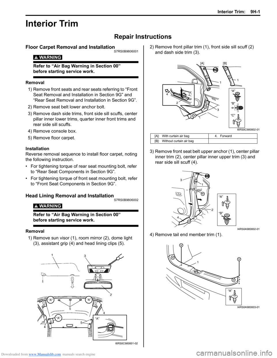
1) Remove sun visor (1), room mirror (2), dome light (3), assistant grip (4) and head lining clips (5). 2) Remove front pillar trim (1
), front side sill scuff (2)
and dash side trim (3).
3) Remove front seat belt u pper anchor (1), center pillar
inner trim (2), center pillar inner upper trim (3) and
rear side sill scuff (4).
4) Remove tail end member trim (1).
I6RS0C980001-02
[A]: With curtain air bag 4. Forward
[B]: Without curtain air bag
“A”“A”
“A”
2
4
1
3
“A”
“A”
1
[B]
[A]
“B”“B”
“C”“C”
I6RS0C980002-01
“A”
“B”
“A”
“B”
1
3
2
4
I4RS0A980002-01
“A”
“A”
“A”
“A”“A”1
I4RS0A980003-01
Page 1368 of 1496

Downloaded from www.Manualslib.com manuals search engine 9H-2 Interior Trim:
5) Remove quarter inner rear upper trim (1), quarter inner rear lower trim (2), quarter inner front trim (3)
and quarter inner upper trim (4).
6) Remove head lining. Installation
Reverse removal procedure noting the following.
• Apply adhesive (1) to head lining (2) as shown in the
figure, and then install head lining (2).
• Tighten sun visor scre w to specified torque.
Tightening torque
Sun visor screw (a): 4 N·m (0.4 kgf-m, 3.0 lb-ft)
Console Box ComponentsS7RS0B9806003
AA
A
A
A
A
DD
B
BB
CC
D
C
A
B
1
2
3
4
A
I7RS0A980001-01
1 1
2
I6RS0C980004-01
I4RS0A980007-01
“B”
“A”
“A”
“A”
“A”“A”
“A”
“A”“A”
“A”
“B”
“B”
1 2
3
4
“C”
“C”
“C”
I4RS0A980008-01
1. Front console box
2. Rear console box 3. Front console box garnish4. Console side cover