Ecu wiring SUZUKI SWIFT 2006 2.G Service Workshop Manual
[x] Cancel search | Manufacturer: SUZUKI, Model Year: 2006, Model line: SWIFT, Model: SUZUKI SWIFT 2006 2.GPages: 1496, PDF Size: 34.44 MB
Page 4 of 1496

Downloaded from www.Manualslib.com manuals search engine 00
0
1
2
3
4
5
6
7
8
9
10
11
Vo l u m e 1
Precautions............................................................... 00-iPrecautions ............................................................ 00-1
General Information ................ ................................... 0-i
General Information ............................................... 0A-1
Maintenance and Lubricatio n ................................. 0B-1
Engine ......................................................................... 1-i Precautions .............................................................. 1-1
Engine General Information and Diagnosis ........... 1A-1
Aux. Emission Control Devices .............................. 1B-1
Engine Electrical Devices....................................... 1C-1
Engine Mechanical ................................................. 1D-1
Engine Lubrication System .................................... 1E-1
Engine Cooling System .......................................... 1F-1
Fuel System ...........................................................1G-1
Ignition System....................................................... 1H-1
Starting System ....................................................... 1I-1
Charging System.....................................................1J-1
Exhaust System ..................................................... 1K-1
Suspension ................................................................. 2-i Precautions .............................................................. 2-1
Suspension General Diagnosis .............................. 2A-1
Front Suspension ................................................... 2B-1
Rear Suspension................ .................................... 2C-1
Wheels and Tires ................................................... 2D-1
Driveline / Axle ........................................................... 3-i Precautions .............................................................. 3-1
Drive Shaft / Axle ................................................... 3A-1
Brakes ......................................................................... 4-i Precautions .............................................................. 4-1
Brake Control System and Diagnosis .................... 4A-1
Front Brakes........................................................... 4B-1
Rear Brakes ........................................................... 4C-1
Parking Brake......................................................... 4D-1
ABS ........................................................................ 4E-1
Electronic Stability Program ................................... 4F-1
Vo l u m e 2
Precautions ............................................................... 00-iPrecautions ............................................................ 00-1
Transmission / Transaxle .... ...................................... 5-i
Precautions .............................................................. 5-1
Automatic Transmission/Transaxle ........................ 5A-1
Manual Transmission/Transaxle ............................ 5B-1
Clutch .....................................................................5C-1
Steering ....................................................................... 6-i Precautions .............................................................. 6-1
Steering General Diagnosis ................................... 6A-1
Steering Wheel and Column .................................. 6B-1
Power Assisted Steering System ...........................6C-1
HVAC ........................................................................... 7-i Precautions .............................................................. 7-1
Heater and Ventilation............................................ 7A-1
Air Conditioning System ......................................... 7B-1
Restraint ...................................................................... 8-i Precautions .............................................................. 8-1
Seat Belts ............................................................... 8A-1
Air Bag System ...................................................... 8B-1
Body, Cab and Accessories .... .................................. 9-i
Precautions .............................................................. 9-1
Wiring Systems ...................................................... 9A-1
Lighting Systems .................................................... 9B-1
Instrumentation / Driver Info. / Horn .......................9C-1
Wipers / Washers ...................................................9D-1
Glass / Windows / Mirrors ...................................... 9E-1
Security and Locks ................................................. 9F-1
Seats ..................................................................... 9G-1
Interior Trim ............................................................9H-1
Hood / Fenders / Doors .......................................... 9J-1
Body Structure ....................................................... 9K-1
Paint / Coatings ...................................................... 9L-1
Exterior Trim .......................................................... 9M-1
Control Systems ....................................................... 10-i Precautions ............................................................ 10-1
Body Electrical Control Sy stem ............................ 10B-1
Immobilizer Control System .................................10C-1
Keyless Start System ........................................... 10E-1
TABLE OF CONTENTS
Page 13 of 1496
Downloaded from www.Manualslib.com manuals search engine Precautions: 00-8
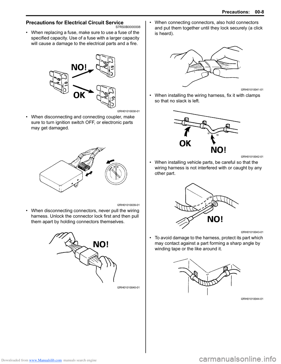
Precautions for Electrical Circuit ServiceS7RS0B0000008
• When replacing a fuse, make sure to use a fuse of the specified capacity. Use of a fuse with a larger capacity
will cause a damage to the electrical parts and a fire.
• When disconnecting and connecting coupler, make sure to turn ignition switch OFF, or electronic parts
may get damaged.
• When disconnecting connectors, never pull the wiring harness. Unlock the connecto r lock first and then pull
them apart by holding connectors themselves. • When connecting connectors, also hold connectors
and put them together until th ey lock securely (a click
is heard).
• When installing the wiring harness, fix it with clamps so that no slack is left.
• When installing vehicle parts, be careful so that the wiring harness is not interfered with or caught by any
other part.
• To avoid damage to the harnes s, protect its part which
may contact against a part forming a sharp angle by
winding tape or the like around it.
I2RH01010038-01
I2RH01010039-01
I2RH01010040-01
I2RH01010041-01
I2RH01010042-01
I2RH01010043-01
I2RH01010044-01
Page 688 of 1496
Downloaded from www.Manualslib.com manuals search engine 5A-44 Automatic Transmission/Transaxle:
DTC P0602: Control Module Programming ErrorS7RS0B5104048
System Description
Internal control module is installed in ECM.
DTC Detecting Condition and Trouble Area
DTC Confirmation Procedure 1) Connect scan tool to DLC with ignition switch turned OFF.
2) Clear DTC, pending DTC and freeze frame data by using scan tool.
3) Start engine and run it at idle if possible.
4) Check DTC.
DTC Troubleshooting
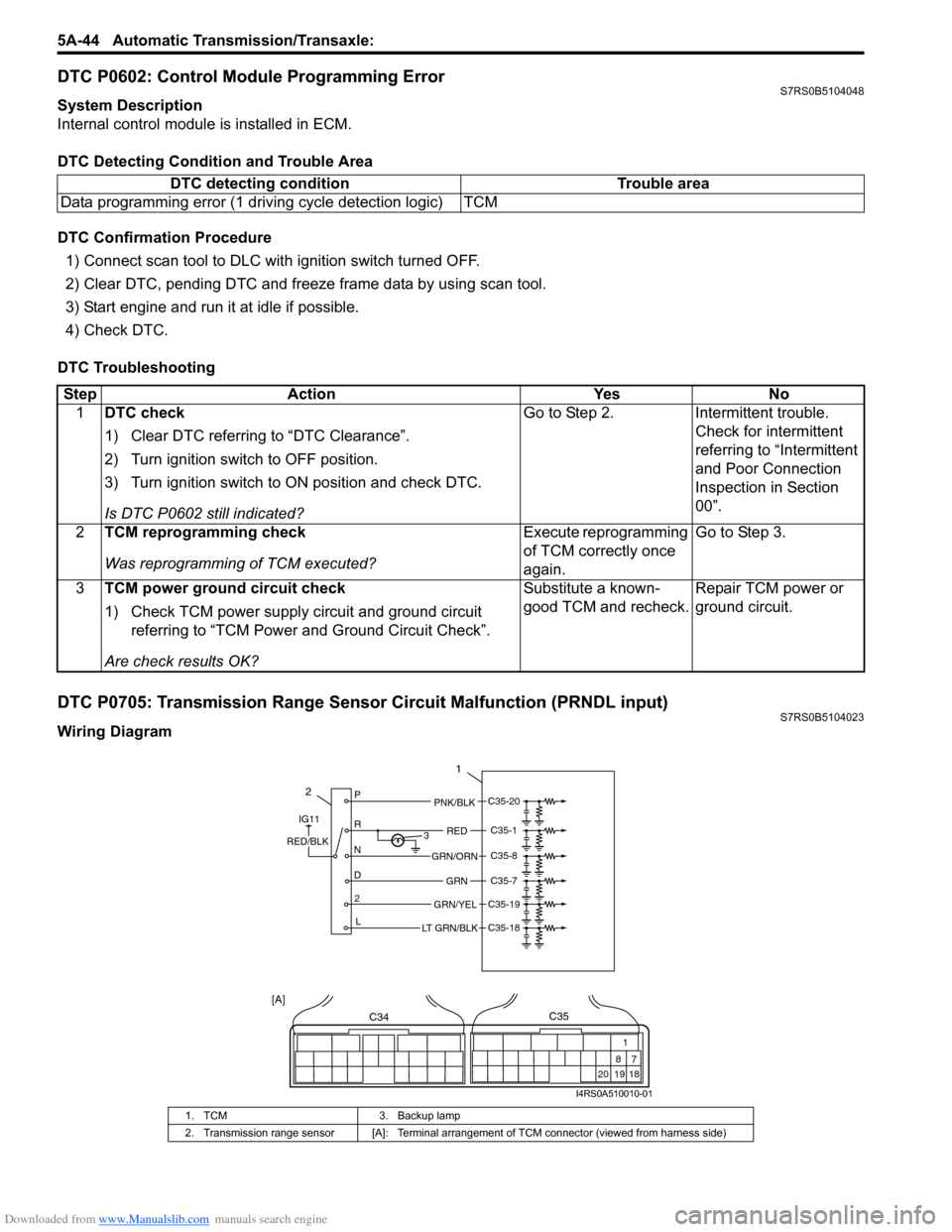
DTC P0705: Transmission Range Sensor Circuit Malfunction (PRNDL input)S7RS0B5104023
Wiring DiagramDTC detecting condition Trouble area
Data programming error (1 driving cycle detection logic) TCM
Step Action YesNo
1 DTC check
1) Clear DTC referring to “DTC Clearance”.
2) Turn ignition switch to OFF position.
3) Turn ignition switch to ON position and check DTC.
Is DTC P0602 still indicated? Go to Step 2.
Intermittent trouble.
Check for intermittent
referring to “Intermittent
and Poor Connection
Inspection in Section
00”.
2 TCM reprogramming check
Was reprogramming of TCM executed? Execute reprogramming
of TCM correctly once
again.Go to Step 3.
3 TCM power ground circuit check
1) Check TCM power supply circuit and ground circuit
referring to “TCM Power and Ground Circuit Check”.
Are check results OK? Substitute a known-
good TCM and recheck.
Repair TCM power or
ground circuit.
1. TCM
3. Backup lamp
2. Transmission range sensor [A]: Terminal arrangem ent of TCM connector (viewed from harness side)
2P
R
N
D 2 L 3
1
PNK/BLK
RED
GRN
GRN/ORN
GRN/YEL
IG11
RED/BLK
LT GRN/BLK
C35-20
C35-1
C35-8
C35-7
C35-19
C35-18
C34
20 19
87
18
1
C35
[A]
I4RS0A510010-01
Page 738 of 1496
Downloaded from www.Manualslib.com manuals search engine 5A-94 Automatic Transmission/Transaxle:
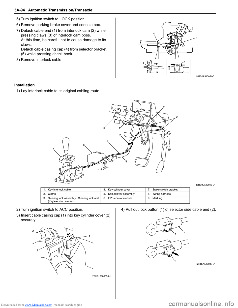
5) Turn ignition switch to LOCK position.
6) Remove parking brake cover and console box.
7) Detach cable end (1) from interlock cam (2) while
pressing claws (3) of interlock cam boss.
At this time, be careful no t to cause damage to its
claws.
Detach cable casing cap (4 ) from selector bracket
(5) while pressing check hook.
8) Remove interlock cable.
Installation 1) Lay interlock cable to its original cabling route.
2) Turn ignition switch to ACC position.
3) Insert cable casing cap (1) into key cylinder cover (2) securely. 4) Pull out lock button (1) of selector side cable end (2).
4
5 31
2
4
I4RS0A510054-01
1 2
3
4
5 6 7
8
2
I6RS0C510013-01
1. Key interlock cable 4. Key cylinder cover7. Brake switch bracket
2. Clamp 5. Select lever assembly 8. Wiring harness
3. Steering lock assembly / Steering lock unit (Keyless start model) 6. EPS control module
9. Marking
1
2
I2RH01510085-01
1
1
2
I2RH01510086-01
Page 824 of 1496
Downloaded from www.Manualslib.com manuals search engine 5B-10 Manual Transmission/Transaxle:
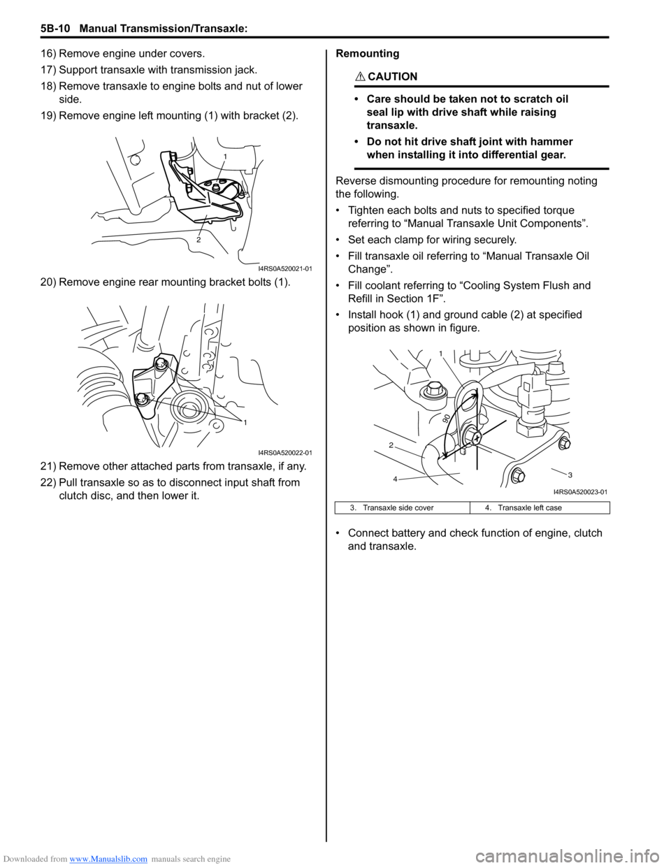
16) Remove engine under covers.
17) Support transaxle with transmission jack.
18) Remove transaxle to engine bolts and nut of lower side.
19) Remove engine left mounting (1) with bracket (2).
20) Remove engine rear mounting bracket bolts (1).
21) Remove other attached parts from transaxle, if any.
22) Pull transaxle so as to disconnect input shaft from clutch disc, and then lower it. Remounting
CAUTION!
• Care should be taken not to scratch oil
seal lip with drive shaft while raising
transaxle.
• Do not hit drive shaft joint with hammer when installing it into differential gear.
Reverse dismounting procedure for remounting noting
the following.
• Tighten each bolts and nuts to specified torque referring to “Manual Transaxle Unit Components”.
• Set each clamp for wiring securely.
• Fill transaxle oil referring to “Manual Transaxle Oil
Change”.
• Fill coolant referring to “Cooling System Flush and
Refill in Section 1F”.
• Install hook (1) and ground cable (2) at specified position as shown in figure.
• Connect battery and check function of engine, clutch
and transaxle.
1
2
I4RS0A520021-01
1
I4RS0A520022-01
3. Transaxle side cover 4. Transaxle left case
90
1
2 3
4
I4RS0A520023-01
Page 1210 of 1496
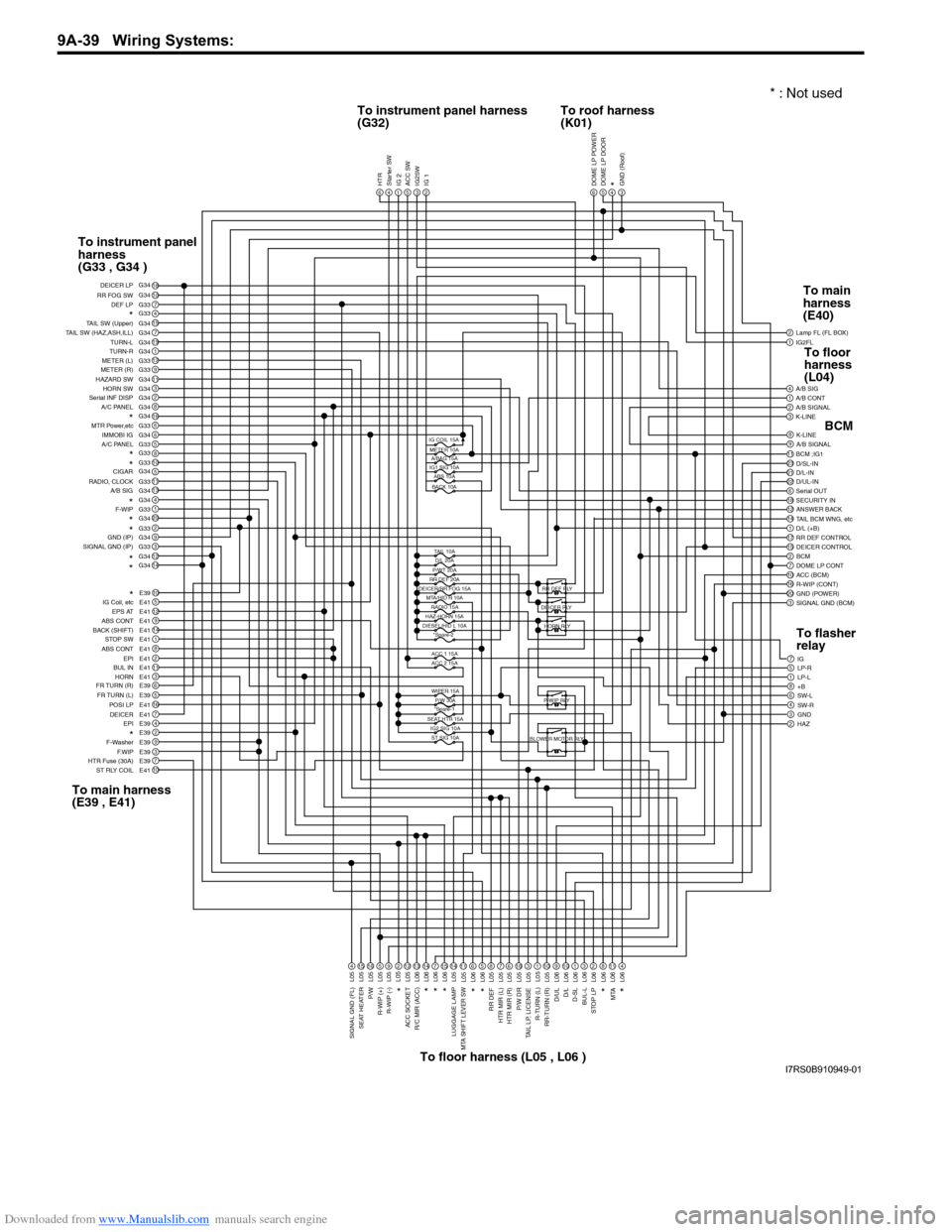
Downloaded from www.Manualslib.com manuals search engine 9A-39 Wiring Systems:
1IG2FL2
6
Lamp FL (FL BOX)
1A/B CONT4A/B SIG
3K-LINE2A/B SIGNAL
9A/B SIGNAL8K-LINE
2311BCM ;IG1
22D/UL-IN21D/L-IN D/SL-IN
18SECURITY IN6Serial OUT
14TAIL BCM WNG, etc12ANSWER BACK
17RR DEF CONTROL1D/L (+B)
2BCM15DEICER CONTROL
10ACC (BCM)7DOME LP CONT
20GND (POWER)16R-WIP (CONT)
3SIGNAL GND (BCM)
7IG
1LP-L5LP-R
8+B6SW-L
3GND4SW-R
2HAZ
DOME LP POWER5DOME LP DOOR4*3GND (Roof)6HTR4Starter SW1IG 25ACC SW3IG2SW2IG 1
18107G33415G347G3419G341G3412G339G3311G343G342G348G34166G336G345G33810511G3313G344G341G3320G342G339G343G3312G3414G34
10E395E4112E419E4114E411E418E412E4111E413E416E395E3916E417E414E392E399E393E397E3910E41
DEF LP
RR FOG SW DEICER LP
*TAIL SW (Upper)
TAIL SW (HAZ,ASH,ILL) TURN-L
TURN-R
METER (L)
METER (R)
HAZARD SW HORN SW
Serial INF DISP
A/C PANEL
*MTR Power,etc
IMMOBI IG
A/C PANEL
*
*
RADIO, CLOCK
A/B SIGCIGAR
*F-WIP*
*GND (IP)
SIGNAL GND (IP)
*
*
*
IG Coil, etc EPS AT
ABS CONT
BACK (SHIFT) STOP SW
ABS CONT EPI
BUL IN
HORN
FR TURN (R)
FR TURN (L) POSI LP
EPI
DEICER
*F-Washer
F.WIP
HTR Fuse (30A)
ST RLY COIL
4L0515L0516L055L059L05212L0513L0614L067L0615L0614L0511L056L065L068L057L056L0518L053L051L0510L059L0610L061L063L062L068L0611L064L06
SIGNAL GND (FL)
SEAT HEATER
P/W
R-WIP (+) R-WIP (-)*
ACC SOCKET
R/C MIR (ACC)
*
*
*
LUGGAGE LAMPMTA SHIFT LEVER SW
*
*
RR DEF
HTR MIR (L)
HTR MIR (R)
P/W DR
TAIL LP, LICENSE
R-TURN (L)
RR-TURN (R)
D/ULD/L
D-SL
BUL-L
STOP LP
MTA
*
*
IG COIL 15AMETER 10A A/BAG 15A
IG1 SIG 10A ABS 10A
BACK 10A
TAIL 10AD/L 20A
P/WT 20A
RR DEF 20A
DEICER/RR FOG 15A
MTA/HID R 10A
ACC 1 15A
ACC 2 15A
WIPER 15A P/W 30A
*Spare-1
SEAT HTR 15A IG2 SIG 10AST SIG 10A
HAZ-HORN 15A
DIESEL/HID L 10A *Spare-2 RR DEF RLY
DEICER RLY HORN RLY
P-WIP RLY
BLOWER MOTOR RLY
G34 G34
G33
G34
G33
G34 G33
L05
RADIO 15A
To instrument panel harness
(G32) To roof harness
(K01)
To instrument panel
harness
(G33 , G34 )
To main harness
(E39 , E41) To floor harness (L05 , L06 ) To main
harness
(E40)
BCM
To flasher
relay To floor
harness
(L04)
* : Not used
I7RS0B910949-01
Page 1212 of 1496
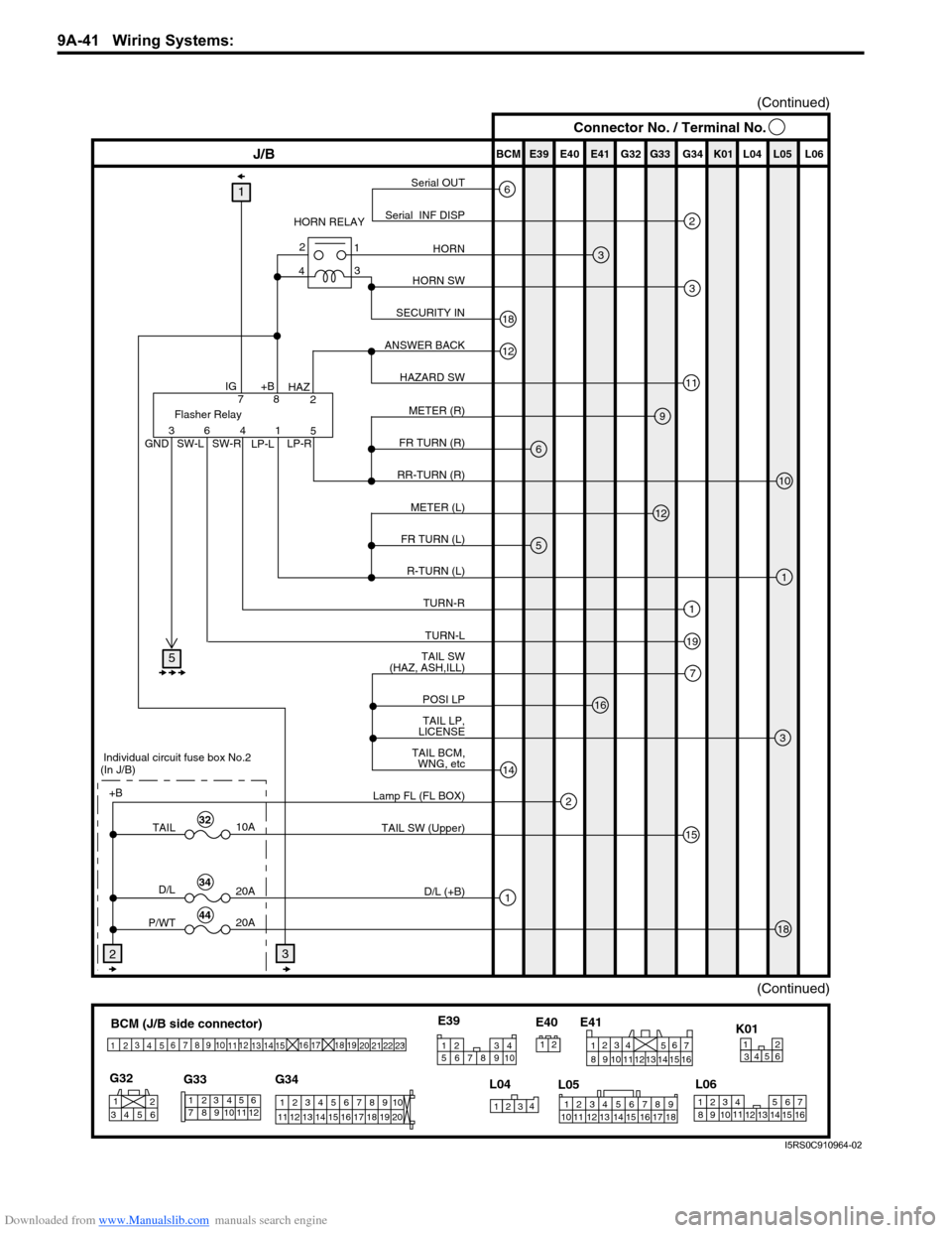
Downloaded from www.Manualslib.com manuals search engine 9A-41 Wiring Systems:
BCM (J/B side connector)
34
1
2 5
15
14
12
13
10
11
9
8
6
7
17
161821 22
19
20
23
1234578 11 6
12
91034 6 52
1
G33
G32
G34
10
11 12 13 14 15 16 17 18 19 123456789
20
345612K01
23414
3
561214
11
10 157
2113 16
98
6
5
4
3
2
1
7
11
10
9
8
15
14
13
12 16
L04
L06
E41
21
12 34 5 6 78 9
15 16 17 18
1110 12 13 14
1
234
5 678 910
E39
L05
E40
E39 E41E40
BCM G34G33G32K01 L04 L05 L06
11
J/B
Flasher Relay 78
2
5
1463
6
12
3
6
9
3
12
1
5
1
19
14
3
18
7
16
2
15
1
10
1Serial OUT
Serial INF DISP
HORN SW
HORN RELAY
GND SW-L SW-R
LP-LLP-R
IG
+B
HAZ HORN
SECURITY IN
ANSWER BACK HAZARD SW
METER (R)
FR TURN (R)
METER (L)
RR-TURN (R)
FR TURN (L) R-TURN (L)
TURN-R
TAIL SW
(HAZ, ASH,ILL) TURN-L
POSI LP TAIL LP,
LICENSE
TAIL BCM, WNG, etc
Lamp FL (FL BOX)
TAIL SW (Upper)
TAIL 10A
+B
D/L 20A
P/WT 20A D/L (+B)
32
(Continued)
Individual circuit fuse box No.2
(In J/B)
32
34
44
(Continued)
1
2
3
4
5
Connector No. / Terminal No.
2
18
I5RS0C910964-02
Page 1349 of 1496
Downloaded from www.Manualslib.com manuals search engine Security and Locks: 9F-3
Diagnostic Information and Procedures
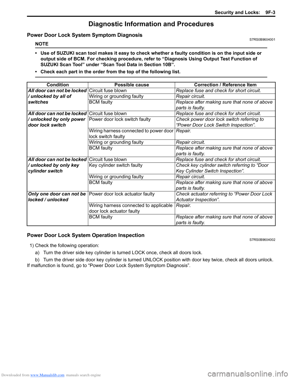
Power Door Lock System Symptom DiagnosisS7RS0B9604001
NOTE
• Use of SUZUKI scan tool makes it easy to check whether a faulty condition is on the input side or
output side of BCM. For checking procedure, re fer to “Diagnosis Using Output Test Function of
SUZUKI Scan Tool” under “Scan Tool Data in Section 10B”.
• Check each part in the order from the top of the following list.
Power Door Lock System Operation InspectionS7RS0B9604002
1) Check the following operation:
a) Turn the driver side key cylinder is turned LOCK once, check all doors lock.
b) Turn the driver side door key cylinder is turned UNLOC K position with door key twice, check all doors unlock.
If malfunction is found, go to “Power Door Lock System Symptom Diagnosis”.
Condition Possible cause Correction / Reference Item
All door can not be locked
/ unlocked by all of
switches Circuit fuse blown
Replace fuse and check for short circuit.
Wiring or grounding faulty Repair circuit.
BCM faulty Replace after making sure that none of above
parts is faulty.
All door can not be locked
/ unlocked by only power
door lock switch Circuit fuse blown
Replace fuse and check for short circuit.
Power door lock switch faulty Check power door lock switch referring to
“Power Door Lock Switch Inspection”.
Wiring harness connected to power door
lock switch faulty Repair.
Wiring or grounding faulty Repair circuit.
BCM faulty Replace after making sure that none of above
parts is faulty.
All door can not be locked
/ unlocked by only key
cylinder switch Circuit fuse blown
Replace fuse and check for short circuit.
Key cylinder switch faulty Check key cylinder switch referring to “Door
Key Cylinder Switch Inspection”.
Wiring or grounding faulty Repair circuit.
BCM faulty Replace after making sure that none of above
parts is faulty.
Only one door can not be
locked / unlocked Power door lock actuator faulty
Check actuator referring to “Power Door Lock
Actuator Inspection”.
Wiring harness connected to applicable
door lock actuator faulty Repair.
BCM faulty Replace after making sure that none of above
parts is faulty.
Page 1350 of 1496
Downloaded from www.Manualslib.com manuals search engine 9F-4 Security and Locks:
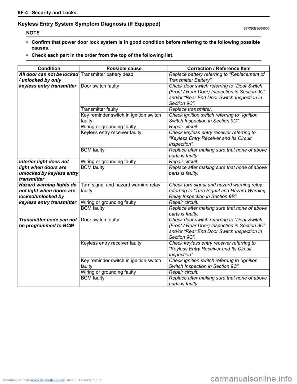
Keyless Entry System Symptom Diagnosis (If Equipped)S7RS0B9604003
NOTE
• Confirm that power door lock system is in good condition before referring to the following possible causes.
• Check each part in the order from the top of the following list.
Condition Possible cause Correction / Reference Item
All door can not be locked
/ unlocked by only
keyless entry transmitter Transmitter battery dead
Replace battery referring to “Replacement of
Transmitter Battery”.
Door switch faulty Check door switch referring to “Door Switch
(Front / Rear Door) Inspection in Section 9C”
and/or “Rear End Door Switch Inspection in
Section 9C”.
Transmitter faulty Replace transmitter.
Key reminder switch in ignition switch
faulty Check ignition switch referring to “Ignition
Switch Inspection in Section 9C”.
Wiring or grounding faulty Repair circuit.
Keyless entry receiver faulty Check keyless entry receiver referring to
“Keyless Entry Receiver and Its Circuit
Inspection”.
BCM faulty Replace after making sure that none of above
parts is faulty.
Interior light does not
light when doors are
unlocked by keyless entry
transmitter Wiring or grounding faulty
Repair circuit.
BCM faulty Replace after making sure that none of above
parts is faulty.
Hazard warning lights do
not light when doors are
locked/unlocked by
keyless entry transmitter Turn signal and hazard warning relay
faulty
Check turn signal and hazard warning relay
referring to “Turn Signal and Hazard Warning
Relay Inspection in Section 9B”.
Wiring or grounding faulty Repair circuit.
BCM faulty Replace after making sure that none of above
parts is faulty.
Transmitter code can not
be programmed to BCM Door switch faulty
Check door switch referring to “Door Switch
(Front / Rear Door) Inspection in Section 9C”
and/or “Rear End Door Switch Inspection in
Section 9C”.
Keyless entry receiver faulty Check keyless entry receiver referring to
“Keyless Entry Receiver and Its Circuit
Inspection”.
Key reminder switch in ignition switch
faulty Check ignition switch referring to “Ignition
Switch Inspection in Section 9C”.
Wiring or grounding faulty Repair circuit.
BCM faulty Replace after making sure that none of above
parts is faulty.
Page 1351 of 1496
Downloaded from www.Manualslib.com manuals search engine Security and Locks: 9F-5
Keyless Entry System Operation InspectionS7RS0B9604004
NOTE
When performing the this inspection, make
sure to have any of the door once opened/
closed after the ignition key has been
removed from the ignition key cylinder.
1) Confirm that power door lock system operates normally, refer to “Power Door Lock System
Operation Inspection”.
2) All doors are closed and unlocked.
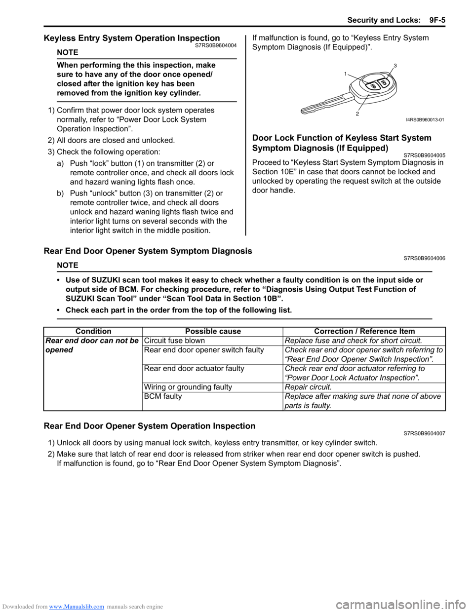
3) Check the following operation: a) Push “lock” button (1 ) on transmitter (2) or
remote controller once, and check all doors lock
and hazard waning lights flash once.
b) Push “unlock” button (3) on transmitter (2) or remote controller twice, and check all doors
unlock and hazard waning lights flash twice and
interior light turns on several seconds with the
interior light switch in the middle position. If malfunction is found, go to “Keyless Entry System
Symptom Diagnosis (If Equipped)”.
Door Lock Function of Keyless Start System
Symptom Diagnosis (If Equipped)
S7RS0B9604005
Proceed to “Keyless Start System Symptom Diagnosis in
Section 10E” in case that doors cannot be locked and
unlocked by operating the request switch at the outside
door handle.
Rear End Door Opener System Symptom DiagnosisS7RS0B9604006
NOTE
• Use of SUZUKI scan tool makes it easy to check wh
ether a faulty condition is on the input side or
output side of BCM. For checking procedure, re fer to “Diagnosis Using Output Test Function of
SUZUKI Scan Tool” under “Scan Tool Data in Section 10B”.
• Check each part in the order from the top of the following list.
Rear End Door Opener System Operation InspectionS7RS0B9604007
1) Unlock all doors by using manu al lock switch, keyless entry transmitter, or key cylinder switch.
2) Make sure that latch of rear end door is released from striker when rear end door opener switch is pushed. If malfunction is found, go to “Rear End Door Opener System Symptom Diagnosis”.
1
3
2I4RS0B960013-01
ConditionPossible cause Correction / Reference Item
Rear end door can not be
opened Circuit fuse blown
Replace fuse and check for short circuit.
Rear end door opener switch faulty Check rear end door opener switch referring to
“Rear End Door Opener Switch Inspection”.
Rear end door actuator faulty Check rear end door actuator referring to
“Power Door Lock Actuator Inspection”.
Wiring or grounding faulty Repair circuit.
BCM faulty Replace after making sure that none of above
parts is faulty.