Injector wiring SUZUKI SWIFT 2006 2.G Service Workshop Manual
[x] Cancel search | Manufacturer: SUZUKI, Model Year: 2006, Model line: SWIFT, Model: SUZUKI SWIFT 2006 2.GPages: 1496, PDF Size: 34.44 MB
Page 48 of 1496

Downloaded from www.Manualslib.com manuals search engine 1-iv Table of Contents
Engine Lubrication System.....................1E-1
General Description ............................................. 1E-1
Engine Lubrication Description ........................... 1E-1
Diagnostic Information and Procedures ............ 1E-2 Oil Pressure Check ............................................. 1E-2
Repair Instructions ........... ................................... 1E-3
Heat Exchanger Components ............................. 1E-3
Heat Exchanger On-Vehicle Inspection .............. 1E-4
Heat Exchanger Removal and Installation .......... 1E-4
Oil Pan and Oil Pump Strainer Components....... 1E-5
Oil Pan and Oil Pump Strainer Removal and
Installation ......................................................... 1E-5
Oil Pan and Oil Pump Stra iner Cleaning ............. 1E-7
Oil Pump Components ........................................ 1E-8
Oil Pump Removal and Installation ..................... 1E-8
Oil Pump Disassembly and Reassembly ............ 1E-8
Oil Pump Inspection ............................................ 1E-9
Specifications .... ................................................. 1E-11
Tightening Torque Specifications ...................... 1E-11
Special Tools and Equipmen t ........................... 1E-11
Recommended Service Material ....................... 1E-11
Special Tool ...................................................... 1E-11
Engine Cooling System ..... ...................... 1F-1
General Description .......... ................................... 1F-1
Cooling System Descriptio n ................................ 1F-1
Coolant Description ............................................. 1F-1
Schematic and Routing Diagram ........................ 1F-2 Coolant Circulation .............................................. 1F-2
Diagnostic Information and Procedures ............ 1F-4 Engine Cooling Symptom Diagnosis ................... 1F-4
Repair Instructions ........... ................................... 1F-5
Cooling System Components.............................. 1F-5
Coolant Level Check ........................................... 1F-6
Engine Cooling System Inspection and Cleaning ............................................................ 1F-6
Cooling System Draining.. ................................... 1F-6
Cooling System Flush and Refill ......................... 1F-7
Cooling Water Pipes or Hoses Removal and Installation ......................................................... 1F-7
Thermostat Removal and In stallation.................. 1F-8
Thermostat Inspection......................................... 1F-8
Radiator Cooling Fan Motor On-Vehicle Inspection .......................................................... 1F-9
Radiator Cooling Fan Rela y Inspection............... 1F-9
Radiator Cooling Fan Removal and Installation ....................................................... 1F-10
Radiator On-Vehicle Inspection and Cleaning .. 1F-10
Radiator Removal and Inst allation .................... 1F-10
Water Pump Removal and In stallation .............. 1F-11
Water Pump Inspection ..................................... 1F-11
Specifications .... ................................................. 1F-12
Tightening Torque Specifications ...................... 1F-12
Special Tools and Equipmen t ........................... 1F-12
Recommended Service Material ....................... 1F-12
Fuel System ................... .......................... 1G-1
Precautions.......................................................... 1G-1 Precautions on Fuel System Service ................. 1G-1
General Description ............................................ 1G-1 Fuel System Description .................................... 1G-1
Fuel Delivery System Description ...................... 1G-1
Fuel Pump Description ....................................... 1G-2
Schematic and Routing Diagram ....................... 1G-2 Fuel Delivery System Diag ram........................... 1G-2
Diagnostic Information and Procedures ........... 1G-2 Fuel Pressure Inspection ................................... 1G-2
Fuel Cut Operation Inspection ........................... 1G-3
Repair Instructions ............ ................................. 1G-4
Fuel System Components .................................. 1G-4
Fuel Hose Disconnecting and Reconnecting ..... 1G-5
Fuel Pressure Relief Procedure ......................... 1G-7
Fuel Leakage Check Procedure......................... 1G-7
Fuel Lines On-Vehicle Inspection ...................... 1G-7
Fuel Pipe Removal and Installation.................... 1G-7
Fuel Injector On-Vehicle Inspection ................... 1G-8
Fuel Injector Removal and Installation ............... 1G-8
Fuel Injector Inspection ...................................... 1G-9
Fuel Filler Cap Inspection . ............................... 1G-10
Fuel Tank Inlet Valve Removal and Installation ...................................................... 1G-11
Fuel Tank Inlet Valve Inspection ...................... 1G-12
Fuel Tank Removal and Installation ................. 1G-12
Fuel Tank Inspection ........................................ 1G-13
Fuel Tank Purging Procedure .......................... 1G-14
Fuel Pump On-Vehicle Inspection.................... 1G-14
Fuel Pump Assembly Removal and Installation ...................................................... 1G-14
Main Fuel Level Sensor Removal and Installation ...................................................... 1G-15
Fuel Pump Inspection ...................................... 1G-16
Specifications ..................... ............................... 1G-16
Tightening Torque Specifications ..................... 1G-16
Special Tools and Equipmen t .......................... 1G-17
Special Tool ..................................................... 1G-17
Ignition System .............. .......................... 1H-1
General Description .............................................1H-1
Ignition System Construction ..............................1H-1
Schematic and Routing Diagram ........................1H-2 Ignition System Wiring Circuit Diagram...............1H-2
Component Location ............ ...............................1H-3
Ignition System Components Location................1H-3
Diagnostic Information and Procedures ............1H-4 Ignition System Symptom Diagnosis...................1H-4
Reference Waveform of Ignition System.............1H-4
Ignition System Check ........................................1H-4
Ignition Spark Test ..............................................1H-6
Repair Instructions ............ ..................................1H-6
High-Tension Cord Removal and Installation......1H-6
High-Tension Cord Inspection.............................1H-7
Spark Plug Removal and Installation ..................1H-7
Spark Plug Inspection .........................................1H-7
Ignition Coil Assembly (Including ignitor)
Removal and Installation ...................................1H-8
Ignition Coil Assembly (Including ignitor)
Inspection ..........................................................1H-8
Page 157 of 1496

Downloaded from www.Manualslib.com manuals search engine Engine General Information and Diagnosis: 1A-107
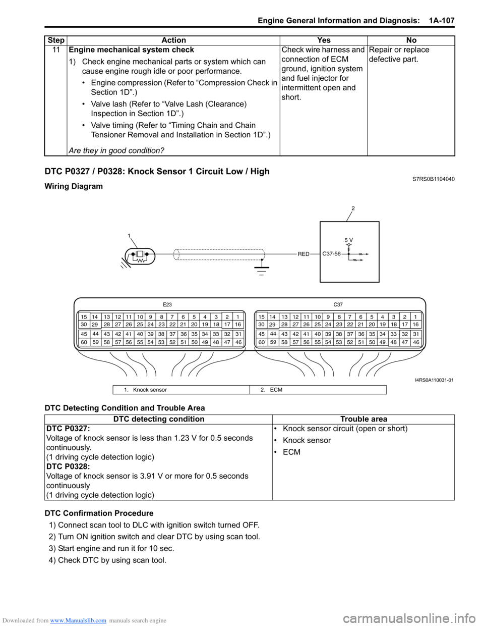
DTC P0327 / P0328: Knock Sensor 1 Circuit Low / HighS7RS0B1104040
Wiring Diagram
DTC Detecting Condition and Trouble Area
DTC Confirmation Procedure1) Connect scan tool to DLC with ignition switch turned OFF.
2) Turn ON ignition switch and clear DTC by using scan tool.
3) Start engine and run it for 10 sec.
4) Check DTC by using scan tool. 11
Engine mechanical system check
1) Check engine mechanical parts or system which can
cause engine rough idle or poor performance.
• Engine compression (Refer to “Compression Check in Section 1D”.)
• Valve lash (Refer to “Valve Lash (Clearance) Inspection in Section 1D”.)
• Valve timing (Refer to “Timing Chain and Chain Tensioner Removal and Installation in Section 1D”.)
Are they in good condition? Check wire harness and
connection of ECM
ground, ignition system
and fuel injector for
intermittent open and
short.
Repair or replace
defective part.
Step
Action YesNo
E23 C37
34
1819
567
1011
17
20
47 46
495051
2122
52 16
25 9
24
14
29
55
57 54 53
59
60 58 2
262728
15
30
56 4832 31
34353637
40
42 39 38
44
45 43 41 331
1213
238
34
1819
567
1011
17
20
47 46
495051
2122
52 16
25 9
24
14
29
55
57 54 53
59
60 58 2
262728
15
30
56 4832 31
34353637
40
42 39 38
44
45 43 41 331
1213
238
1 2
REDC37-56
5 V
I4RS0A110031-01
1. Knock sensor
2. ECM
DTC detecting condition Trouble area
DTC P0327:
Voltage of knock sensor is less than 1.23 V for 0.5 seconds
continuously.
(1 driving cycle detection logic)
DTC P0328:
Voltage of knock sensor is 3.91 V or more for 0.5 seconds
continuously
(1 driving cycle detection logic) • Knock sensor circuit (open or short)
• Knock sensor
•ECM
Page 244 of 1496

Downloaded from www.Manualslib.com manuals search engine 1A-194 Engine General Information and Diagnosis:
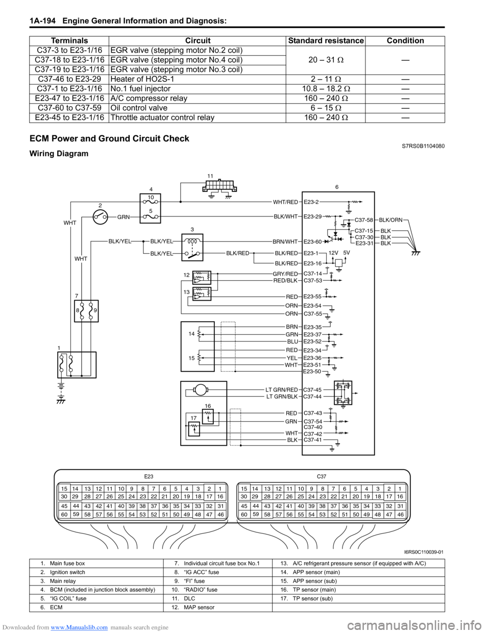
ECM Power and Ground Circuit CheckS7RS0B1104080
Wiring DiagramC37-3 to E23-1/16 EGR valve
(stepping motor No.2 coil)
20 – 31 Ω —
C37-18 to E23-1/16 EGR valv e (stepping motor No.4 coil)
C37-19 to E23-1/16 EGR valv e (stepping motor No.3 coil)
C37-46 to E23-29 Heater of HO2S-1 2 – 11 Ω—
C37-1 to E23-1/16 No.1 fuel injector 10.8 – 18.2 Ω —
E23-47 to E23-1/16 A/C compressor relay 160 – 240 Ω —
C37-60 to C37-59 Oil control valve 6 – 15 Ω —
E23-45 to E23-1/16 Throttle actuator control relay 160 – 240 Ω —
Terminals
CircuitStandard resistance Condition
E23 C37
34
1819
567
1011
17
20
47 46
495051
2122
52 16
25 9
24
14
29
55
57 54 53
59
60 58 2
262728
15
30
56 4832 31
34353637
40
42 39 38
44
45 43 41 331
1213
238
34
1819
567
1011
17
20
47 46
495051
2122
52 16
25 9
24
14
29
55
57 54 53
59
60 58 2
262728
15
30
56 4832 31
34353637
40
42 39 38
44
45 43 41 331
1213
238
BLK/RED
BLK/REDBLK/RED
BLK/YELBLK/YEL
BLK/YEL
GRN
BRN/WHT
12V
5VE23-1
E23-60
E23-16
WHT 2
4
11
6
3
12
13 14
7
1
16
17
89
15
10
5
WHT/REDE23-2
C37-58
C37-15C37-30
BLK/ORN
BLKBLKE23-31BLK
WHT
GRY/REDRED/BLK
ORN
C37-14C37-53
C37-55E23-54
REDE23-55
GRNBRN
BLU
REDYELWHT
E23-35E23-37E23-52
E23-51
E23-34E23-36
E23-50
LT GRN/REDLT GRN/BLKC37-45C37-44
C37-43
C37-54C37-40C37-42C37-41
RED
GRN
WHTBLK
ORN
BLK/WHTE23-29
I6RS0C110039-01
1. Main fuse box 7. Individual circuit fuse box No.1 13. A/C refrigerant pressure sensor (if equipped with A/C)
2. Ignition switch 8. “IG ACC” fuse14. APP sensor (main)
3. Main relay 9. “FI” fuse15. APP sensor (sub)
4. BCM (included in junction block assembly) 10. “RADIO” fuse 16. TP sensor (main)
5. “IG COIL” fuse 11. DLC17. TP sensor (sub)
6. ECM 12. MAP sensor
Page 248 of 1496

Downloaded from www.Manualslib.com manuals search engine 1A-198 Engine General Information and Diagnosis:
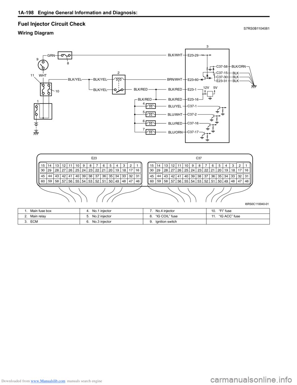
Fuel Injector Circuit CheckS7RS0B1104081
Wiring Diagram
BLK/WHTBLK/RED
BLK/RED
WHTBLK/YELBLK/YEL
BLK/YEL
GRN
BRN/WHT
12V 5V
9
2
8 3E23-29
E23-1
E23-60
10
11
E23
C37
34
1819
567
1011
17
20
47 46
495051
2122
52 16
25 9
24
14
29
55
57 54 53
59
60 58 2
262728
15
30
56 4832 31
34353637
40
42 39 38
44
45 43 41 331
1213
238
34
1819
567
1011
17
20
47 46
495051
2122
52 16
25 9
24
14
29
55
57 54 53
59
60 58 2
262728
15
30
56 4832 31
34353637
40
42 39 38
44
45 43 41 331
1213
238
C37-1
C37-2
C37-16
C37-17
BLK/REDBLK/RED
BLU/YEL
BLU/RED
BLU/ORN
BLU/WHT
E23-16
4
5
6
71
C37-58
C37-15 C37-30 E23-31
BLK/ORN
BLKBLKBLK
I6RS0C110040-01
1. Main fuse box 4. No.1 injector 7. No.4 injector10. “FI” fuse
2. Main relay 5. No.2 injector 8. “IG COIL” fuse 11. “IG ACC” fuse
3. ECM 6. No.3 injector 9. Ignition switch
Page 1174 of 1496

Downloaded from www.Manualslib.com manuals search engine 9A-3 Wiring Systems:
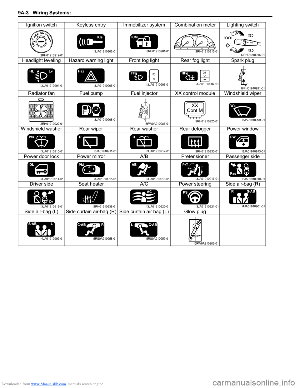
Ignition switch Keyless entry Immobilizer system Combination meter Lighting switch
Headlight leveling Hazard warning light Front fog light Rear fog light Spark plug Radiator fan Fuel pumpFuel injectorXX control module Windshield wiper
Windshield washer Rear wiper Rear washer Rear defogger Power window
Power door lock Power mirror A/BPretensioner Passenger side
Driver side Seat heater A/CPower steering Side air-bag (R)
Side air-bag (L) Side curtain air-bag (R) Side curtain air bag (L) Glow plug
I2RH01910912-01I3JA01910902-01I5RH01910901-01I2RH01910915-01I2RH01910916-01
I3JA01910904-01I3JA01910905-01I3JA01910906-01I3JA01910907-01I2RH01910921-01
I2RH01910922-01I3JA01910908-01I5RW0A910987-01
XX
Cont M
I2RH01910925-01I3JA01910909-01
I3JA01910910-01I3JA01910911-01I3JA01910912-01I2RH01910930-01I3JA01910913-01
I3JA01910914-01I3JA01910915-01I3JA01910916-01I3JA01910917-01I3JA01910918-01
I3JA01910919-01I2RH01910938-01I3JA01910920-01I3JA01910921-01I4JA01910901-01
I4JA01910902-01I5RS0A910958-01I5RS0A910959-01
I5RW0A910986-01
Page 1175 of 1496
![SUZUKI SWIFT 2006 2.G Service Workshop Manual Downloaded from www.Manualslib.com manuals search engine Wiring Systems: 9A-4
How to Read Connector Layout DiagramS7RS0B9101004
[A-1]: Harness symbol and corresponding harness name
A: Battery harness SUZUKI SWIFT 2006 2.G Service Workshop Manual Downloaded from www.Manualslib.com manuals search engine Wiring Systems: 9A-4
How to Read Connector Layout DiagramS7RS0B9101004
[A-1]: Harness symbol and corresponding harness name
A: Battery harness](/img/20/7607/w960_7607-1174.png)
Downloaded from www.Manualslib.com manuals search engine Wiring Systems: 9A-4
How to Read Connector Layout DiagramS7RS0B9101004
[A-1]: Harness symbol and corresponding harness name
A: Battery harness
B: A/C harness
C: Engine harness
D: Injector harness
E: Main harness, Oil pressure switch wire, Console wire
G: Instrument panel harness
J: Side door wire (Power window)
K: Interior light harness, Rear speaker wire, Roof wire
L: Floor harness, G sensor wire (Fuel pump harness)
M: Rear bumper harness
O: Rear end door harness
Q: Air bag/Pretensioner harness
R: (Fuel pump wire)
[A-2]: Connector Number
[B]: Ground point No.
12
11
[B] [B]
Connector code
[A-1] [A-2]L 36
L13 L15
R01
L14
L12
L11L10
L09 L36
R02
L24
L25
L33
L28
L20 L26 (TO O01)
{
L05
L16
L32
L19
L01 (TO G01)
L02 (TO E04)
L03 (TO E05)
L42
R05
R04
L07 (TO K02)
I2RH01910901-01
Page 1182 of 1496

Downloaded from www.Manualslib.com manuals search engine 9A-11 Wiring Systems:
C: Engine harnessNo./Color Connective position No./Color Connective positionC01/GRY IAC valve C22/- Generator #2
C02/GRY IG Coil #1 C23/BLK Starting motor #1
C03/GRY IG Coil #2 C24/- Starting motor #2
C04/GRY Fuel injector #1 C25/GR Y VSS (Vehicle speed sensor)
C05/GRY Fuel injector #2 C26/GRY Knock sensor
C06/GRY Fuel injector #3 C27/BLU (A/
T) Input shaft speed sensor
C07/GRY Fuel injector #4 C28/GRY
(A/T) Trans axle range sensor
C08/BLK or GRY CMP sensor C29/GRY
(A/T) Shift solenoid
C09/BLK ECT sensor C30/BLK
(M/T) Back-up light switch
C10/GRY EGR stepper motor C31/- Main fuse box C11/BLK Throttle position sensor C32/GRY
(IF EQPD) Current sensor
C12/BLK MAP sensor C33/- Main fuse box
C13/BLK MAF sensor C34/N (A/T) TCM
C14/BLK EVAP canister purge valve C35/N (A/T) TCM
C15/GRY Heated oxygen sensor #1 C36/N Main harness (To E24)
C16/GRN Heated oxygen sensor #2 C37/GRY ECM C17/BLK A/C compressor C38/- Weld splice C18/N Oil pressure switch C39/- Weld splice
C19/BLU VVT solenoid C40/- Weld splice
C20/GRY CKP sensor C41/- Weld splice
C21/GRY or BLK Generator #1
Page 1184 of 1496

Downloaded from www.Manualslib.com manuals search engine 9A-13 Wiring Systems:
C: Engine harness
D: Oil pressure switch wireNo./Color Connective position No./Color Connective position
C02/GRY IG Coil #1 C24/- Starting motor #2
C03/GRY IG Coil #2 C23/BLK Starting motor #1
C04/GRY Fuel injector #1 C25/GRY
(A/T) VSS (Vehicle speed sensor)
C05/GRY Fuel injector #2 C26/GRY Knock shaft speed sensor
C06/GRY Fuel injector #3 C27/BLU (A/
T) Input shaft speed sensor
C07/GRY Fuel injector #4 C28/GRY
(A/T) Trans axle range sensor
C08/BLK CMP sensor C29/GRY
(A/T) Shift solenoid
C09/BLK ECT sensor C30/BLK
(M/T) Back-up light switch
C10/GRY EGR stepper motor C31/- Main fuse box C12/BLK MAP sensor C32/GRY Current sensor
C13/BLK MAF sensor C33/- Main fuse box
C14/BLK EVAP canister purge valve C34/N (A/T) TCM
C15/BLK Heated oxygen sensor #1 C35/N (A/T) TCM
C16/GRN Heated oxygen sensor #2 C36/N Main harness (To E24) C17/BLK A/C compressor C37/GRY ECM C18/N Oil pressure switch wire (To D02) C38/- Weld splice
C19/BLU VVT solenoid C39/- Weld splice
C20/GRY CKP sensor C40/- Weld splice C21/BLK Generator #1 C42/BLK Electric throttle body C22/- Generator #2
No./Color Connective position No./ColorConnective position
D01/N Oil pressure switch D02/GRY Engine harness (To C18)