Steering pump SUZUKI SWIFT 2006 2.G Service Workshop Manual
[x] Cancel search | Manufacturer: SUZUKI, Model Year: 2006, Model line: SWIFT, Model: SUZUKI SWIFT 2006 2.GPages: 1496, PDF Size: 34.44 MB
Page 62 of 1496
Downloaded from www.Manualslib.com manuals search engine 1A-12 Engine General Information and Diagnosis:
Electronic Control System DescriptionS7RS0B1101011
The electronic control system consists of 1) various sensors which detect the state of engine and driving conditions, 2)
ECM which controls various devices ac cording to the signals from the sensors and 3) various controlled devices.
Functionally, it is divided into the following sub systems:
• Fuel injection control system
• Ignition control system
• Electric throttle body control system
• Fuel pump control system
• Radiator cooling fan control system
• Evaporative emission control system
• EGR system
• Oxygen sensor heater control system
• A/C control system (A/C model)
• Camshaft position control system
• Immobilizer control system
• Generator control system
• Controller (computer) communication system
Especially, ECM, BCM, combination meter, TCM (A/T model), ABS/ESP ® control module, steering angle sensor
(ESP® model) and keyless start control module (if equipped) intercommunicate by means of CAN communication.
Page 63 of 1496
Downloaded from www.Manualslib.com manuals search engine Engine General Information and Diagnosis: 1A-13
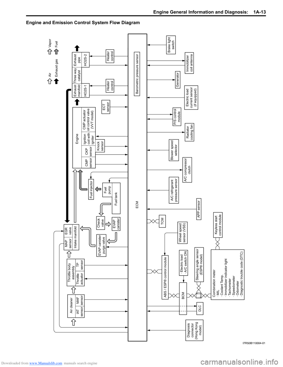
Engine and Emission Control System Flow Diagram
Intake manifold
Exhaust gas AirFuel
Va p o r
EVAP canister purge valve
ECM
Barometric pressure sensor
A/C compressor clutch
Generator
Immobilizer
coil antenna
P/S controlmodule
Brake light switch
Air cleaner
IAT
sensor MAF
sensor
A/C refrigerant
pressure sensor
TP
sensor
Throttle body
assembly
Throttle
actuator
Wheel speed
sensor (VSS)
Steering angle sensor (ESP® model)
ABS / ESP® control module
Blower speed
selector
MAP
sensor EGR
valve
Check valve
EVAP
canisterTCM
Exhaust
manifold Exhaust
pipe
Fuel injector
ECT
sensor
Heater
control
HO2S-1 HO2S-2
Engine
CMP
sensor CKP
sensor
Knock
sensor Ignition
coil with
igniter
Fuel tank
Fuel
pump CMP actuator
oil control valve (VVT model) Three way
catalyst
Heater
control
Radiator
cooling fan
Combination meter
· MIL
· Coolant Temp.
· Immobilizer indicator light
· Tachometer
· Speedometer
· Odometer
· Diagnostic trouble code (DTC)
Keyless start
control module
DLC
· Electric load
· A/C switch ON
BCM
Diagnosis
connector
(Hong Kong model) Electric load
current sensor (if equipped)
APP sensor
I7RS0B110004-01
Page 71 of 1496
Downloaded from www.Manualslib.com manuals search engine Engine General Information and Diagnosis: 1A-21
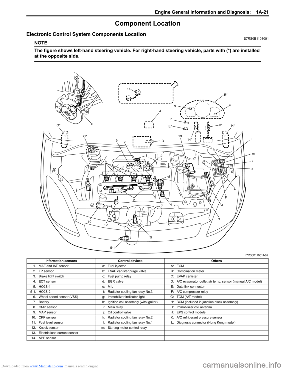
Component Location
Electronic Control System Components LocationS7RS0B1103001
NOTE
The figure shows left-hand steering vehicle. For right-hand steering vehicle, parts with (*) are installed
at the opposite side.
I*
E*
G*
D
K H*
J
C*
7
A
F
c
L
i m
f
B*
e
g
k
l
13
3*
4
j
10 12 h
58
a
9
b
1
5-1
d
2
11
6
14*
I7RS0B110011-02
Information sensors Control devices Others
1. MAF and IAT sensor a: Fuel injectorA: ECM
2. TP sensor b: EVAP canister purge valve B: Combination meter
3. Brake light switch c: Fuel pump relayC: EVAP canister
4. ECT sensor d: EGR valveD: A/C evaporator outlet air temp. sensor (manual A/C model)
5. HO2S-1 e: MILE: Data link connector
5-1. HO2S-2 f: Radiator cooling fan relay No.3F: A/C compressor relay
6. Wheel speed sensor (VSS) g: Immobilizer indicator lightG: TCM (A/T model)
7. Battery h: Ignition coil assembly (with ignitor) H: BCM (included in junction block assembly)
8. CMP sensor i: Main relayI: Immobilizer coil antenna
9. MAP sensor j: Oil control valveJ: EPS control module
10. CKP sensor k: Radiator cooling fan relay No.2K: A/C refrigerant pressure sensor
11. Fuel level sensor l: Radiator cooling fan relay No.1L: Diagnosis connector (Hong Kong model)
12. Knock sensor m: Starting motor control relay
13. Electric load current sensor
14. APP sensor
Page 497 of 1496
Downloaded from www.Manualslib.com manuals search engine Table of Contents 4-iii
ABS Warning Lamp Check ............................... 4F-14
EBD Warning Lamp (Brake Warning Lamp) Check .............................................................. 4F-15
DTC Check ....................................................... 4F-15
DTC Table ......................................................... 4F-15
DTC Clearance ................................................. 4F-18
Fail-Safe Table ................ .................................. 4F-19
Scan Tool Data ................................................. 4F-20
Visual Inspection ............................................... 4F-21
ESP ® Warning Lamp Does Not Come ON at
Ignition Switch ON .......................................... 4F-21
ESP ® Warning Lamp Comes ON Steady......... 4F-22
ABS Warning Lamp Does Not Come ON at Ignition Switch ON .......................................... 4F-23
ABS Warning Lamp Comes ON Steady............ 4F-24
EBD Warning Lamp (Brake Warning Lamp) Comes ON Steady .......................................... 4F-24
Serial Data Link Circuit Check .......................... 4F-26
DTC C1016: Stop Lamp Swit ch Circuit Failure .. 4F-28
DTC C1017 / C1023: Yaw Rate / G Sensor Assembly Failure ............................................ 4F-29
DTC C1018: Brake Fluid Le vel Switch Failure .. 4F-30
DTC 1020: Master Cylinder Pressure Sensor Power Supply Failure ...................................... 4F-31
DTC C1021, C1022 / C1025, C1026 / C1031, C1032 / C1035, C1036: Wheel Speed
Sensor Circuit or Encode r Failure ................... 4F-32
DTC C1024: Steering Angle Sensor Circuit
Failure ............................................................. 4F-34
DTC C1027: ESP ® OFF Switch Circuit
Failure ............................................................. 4F-34
DTC C1028: Master Cylinder Pressure Sensor Circuit Failure ....... .............................. 4F-35
DTC C1034: Yaw Rate / G Sensor Assembly Power Supply Failure ...................................... 4F-36
DTC C1037: Steering Angle Sensor Power Supply Failure ................................................. 4F-37
DTC C1038: Steering Angle Sensor Detect Rolling Counter Fa ilure from ESP® Control
Module ............................................................ 4F-38
DTC C1039: Yaw Rate / G Sensor Assembly Internal Failure .............. .................................. 4F-39
DTC C1040: Stability Control System Function Failure .............................................. 4F-39
DTC C1041 / C1042 / C1043 / C1044 / C1045 / C1046 / C1051 / C1052 / C1053 / C1054 /
C1055 / C1056: Solenoid Circuit Failure ......... 4F-40
DTC C1057: ESP ® Control Module Power
Supply Circuit Failure .... .................................. 4F-41
DTC C1061: Pump Motor and/or Motor Driver Circuit Failure .................................................. 4F-42
DTC C1063: Solenoid Valve Power Supply Driver Circuit Failure ....................................... 4F-43
DTC 1071: ESP ® Control Module Internal
Defect.............................................................. 4F-44 DTC C1073: Lost Communication With Yaw
Rate / G Sensor Assembly .............................. 4F-45
DTC C1075 / 1076 / 1078: Sensor Calibration Incomplete.......................... ............................. 4F-46
DTC C1090: Invalid Communication with
ECM ................................................................ 4F-47
DTC C1091 / C1094: ECM Data in CAN Line Failure / Invalid Torque Control
Communication with ECM .. ............................. 4F-48
DTC U1073: Control Module Communication Bus Off ............................................................ 4F-49
DTC U1100: Lost Communication with ECM (Reception Error)............................................. 4F-50
DTC U1126: Lost Communication with Steering Angle Sensor (Reception Error)........ 4F-51
DTC U1140: Lost Communication with BCM (Reception Error)............................................. 4F-52
Repair Instructions ........... ................................. 4F-54
ESP® Hydraulic Unit Operation Check ............. 4F-54
Sensor Calibration............................................. 4F-54
ESP® Hydraulic Unit / Control Module
Assembly On-Vehicle Inspection .................... 4F-55
ESP ® Hydraulic
Unit / Control Module
Assembly Removal and Inst allation ................ 4F-56
Front / Rear Wheel Speed Sensor On-Vehicle Inspection ........................................................ 4F-57
Front Wheel Speed Sensor Removal and Installation ....................................................... 4F-58
Front Wheel Speed Sensor Inspection ............. 4F-59
Rear Wheel Speed Sensor Removal and Installation ....................................................... 4F-59
Rear Wheel Speed Sensor Inspection .............. 4F-60
Front Wheel Encode r On-Vehicle Inspection .... 4F-61
Front Wheel Encoder Removal and Installation ....................................................... 4F-61
Rear Wheel Encoder On-Veh icle Inspection..... 4F-61
Rear Wheel Encoder Removal and Installation ....................................................... 4F-61
Master Cylinder Pressure Sensor On-Vehicle
Inspection ........................................................ 4F-61
Yaw Rate / G Sensor Assembly On-Vehicle Inspection ........................................................ 4F-62
Yaw Rate / G Sensor Assembly Removal and Installation ....................................................... 4F-63
Yaw Rate / G Sensor Inspection ....................... 4F-64
Steering Angle Sensor On-Vehicle Inspection .. 4F-64
Steering Angle Sensor Removal and Installation ....................................................... 4F-65
Steering Angle Sensor Inspection ..................... 4F-65
ESP® OFF Switch Removal an d Installation .... 4F-65
ESP® OFF Switch Inspection ........................... 4F-65
Specifications .................... ................................. 4F-66
Tightening Torque Specifications ...................... 4F-66
Special Tools and Equipmen t ........................... 4F-66
Special Tool ...................................................... 4F-66
Page 551 of 1496
Downloaded from www.Manualslib.com manuals search engine ABS: 4E-12
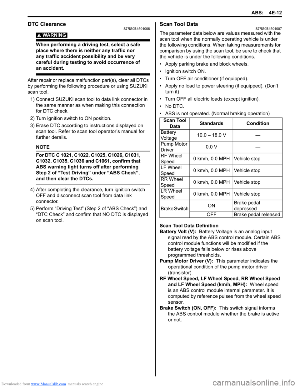
DTC ClearanceS7RS0B4504006
WARNING!
When performing a driving test, select a safe
place where there is neither any traffic nor
any traffic accident possibility and be very
careful during testing to avoid occurrence of
an accident.
After repair or replace malfunction part(s), clear all DTCs
by performing the following procedure or using SUZUKI
scan tool.
1) Connect SUZUKI scan tool to data link connector in the same manner as when making this connection
for DTC check.
2) Turn ignition switch to ON position.
3) Erase DTC according to instructions displayed on scan tool. Refer to scan tool operator’s manual for
further derails.
NOTE
For DTC C 1021, C1022, C1025, C1026, C1031,
C1032, C1035, C1036 and C1061, confirm that
ABS warning light turns off after performing
Step 2 of “Test Driving” under “ABS Check”,
and then clear the DTCs.
4) After completing the clear ance, turn ignition switch
OFF and disconnect scan tool from data link
connector.
5) Perform “Driving Test” (S tep 2 of “ABS Check”) and
“DTC Check” and confirm that NO DTC is displayed
on scan tool.
Scan Tool DataS7RS0B4504007
The parameter data below are values measured with the
scan tool when the normally operating vehicle is under
the following conditions. When taking measurements for
comparison by using the scan tool, be sure to check that
the vehicle is under the following conditions.
• Apply parking brake and block wheels.
• Ignition switch ON.
• Turn OFF air conditioner (if equipped).
• Apply no load to power steering (if equipped). (Don’t turn it)
• Turn OFF all electric loads (except ignition).
• No DTC.
• ABS is not operated. (N ormal braking operation)
Scan Tool Data Definition
Battery Volt (V): Battery Voltage is an analog input
signal read by the ABS control module. Certain ABS
control module function s will be modified if the
battery voltage falls below or rises above
programmed thresholds.
Pump Motor Driver (V): This parameter indicates the
operational condition of the pump motor driver
(transistor).
RF Wheel Speed, LF Wheel Speed, RR Wheel Speed and LF Wheel Speed (km/h, MPH): Wheel speed
is an ABS control module inte rnal parameter. It is
computed by reference pulses from the wheel speed
sensor.
Brake Switch (ON, OFF): This switch signal informs
the ABS control modu le whether the brake is active
or not.
Scan Tool
Data Standards Condition
Battery
Voltage 10.0 – 18.0 V —
Pump Motor
Driver 0.0 V —
RF Wheel
Sp ee d 0 km/h, 0.0 MPH Vehicle stop
LF Wheel
Sp ee d 0 km/h, 0.0 MPH Vehicle stop
RR Wheel
Sp ee d 0 km/h, 0.0 MPH Vehicle stop
LR Wheel
Sp ee d 0 km/h, 0.0 MPH Vehicle stop
Brake Switch ONBrake pedal
depressed
OFF Brake pedal released
Page 577 of 1496
Downloaded from www.Manualslib.com manuals search engine Electronic Stability Program: 4F-3
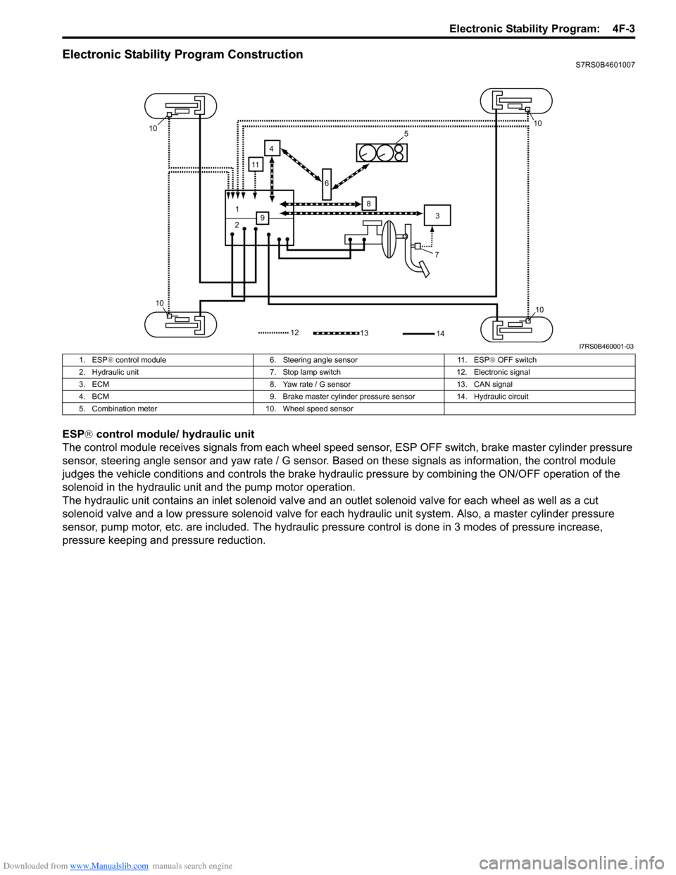
Electronic Stability Program ConstructionS7RS0B4601007
ESP® control module/ hydraulic unit
The control module receives signals from each wheel speed sensor, ESP O FF switch, brake master cylinder pressure
sensor, steering angle sensor and yaw rate / G sensor. Ba sed on these signals as information, the control module
judges the vehicle conditions and controls the brake hydraulic pressure by combining the ON/OFF operation of the
solenoid in the hydraulic unit and the pump motor operation.
The hydraulic unit contains an inlet so lenoid valve and an outlet solenoid valve for each wheel as well as a cut
solenoid valve and a low pressure solenoid valve for each hydraulic unit system. Also, a master cylinder pressure
sensor, pump motor, etc. are included. The hydraulic pre ssure control is done in 3 modes of pressure increase,
pressure keeping and pressure reduction.
7
1
2 3
4
5
6
8
9
10
1010
10
1312
11
14
I7RS0B460001-03
1. ESP ® control module 6. Steering angle sensor 11. ESP ® OFF switch
2. Hydraulic unit 7. Stop lamp switch 12. Electronic signal
3. ECM 8. Yaw rate / G sensor 13. CAN signal
4. BCM 9. Brake master cylinder pre ssure sensor 14. Hydraulic circuit
5. Combination meter 10. Wheel speed sensor
Page 578 of 1496
Downloaded from www.Manualslib.com manuals search engine 4F-4 Electronic Stability Program:
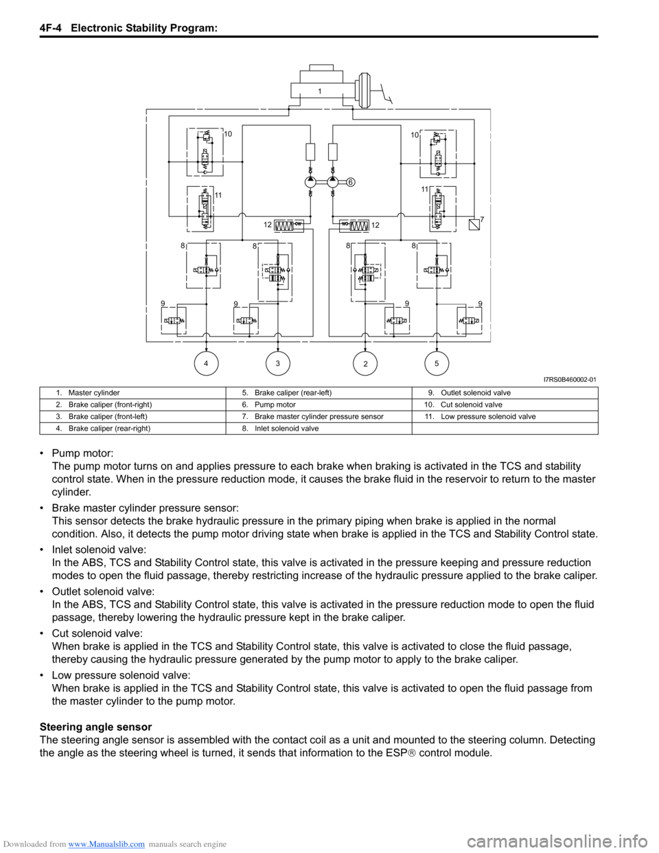
• Pump motor:The pump motor turns on and applies pressure to each brake when braking is activated in the TCS and stability
control state. When in the pressure reduction mode, it causes the brake fluid in the reservoir to return to the master
cylinder.
• Brake master cylinder pressure sensor: This sensor detects the brake hydraulic pressure in th e primary piping when brake is applied in the normal
condition. Also, it detects the pump motor driving state wh en brake is applied in the TCS and Stability Control state.
• Inlet solenoid valve: In the ABS, TCS and Stability Control stat e, this valve is activated in the pressure keeping and pressure reduction
modes to open the fluid passage, thereby restricting increase of the hydraulic pressure applied to the brake caliper.
• Outlet solenoid valve: In the ABS, TCS and Stability Control state, this valve is activated in the pressure reduction mode to open the fluid
passage, thereby lowering the hydraulic pressure kept in the brake caliper.
• Cut solenoid valve: When brake is applied in the TCS and Stability Control state, this valve is activated to close the fluid passage,
thereby causing the hydraulic pressure generated by the pump motor to apply to the brake caliper.
• Low pressure solenoid valve: When brake is applied in the TCS and Stab ility Control state, this valve is activated to open the fluid passage from
the master cylinder to the pump motor.
Steering angle sensor
The steering angle sensor is assembled with the contact co il as a unit and mounted to the steering column. Detecting
the angle as the steering wheel is turned, it sends that information to the ESP ® control module.
1
10 10
11 11
6
7
12 12
8 8 88
9 9 9
9
43 5 2
I7RS0B460002-01
1. Master cylinder 5. Brake caliper (rear-left)9. Outlet solenoid valve
2. Brake caliper (front-right) 6. Pump motor10. Cut solenoid valve
3. Brake caliper (front-left) 7. Brake master cylinder pressure sensor 11. Low pressure solenoid valve
4. Brake caliper (rear-right) 8. Inlet solenoid valve
Page 582 of 1496
Downloaded from www.Manualslib.com manuals search engine 4F-8 Electronic Stability Program:
Schematic and Routing Diagram
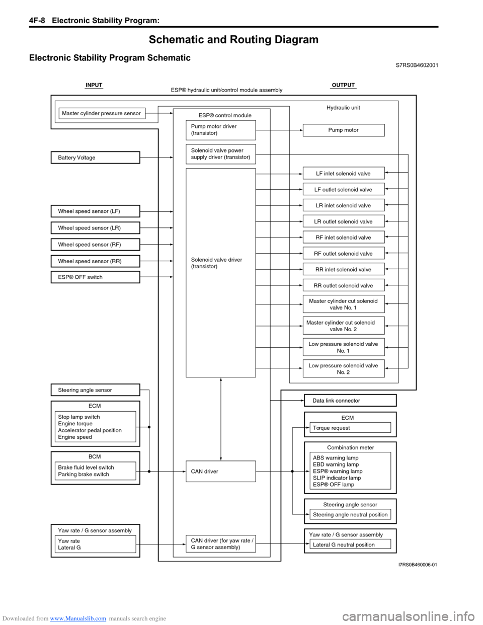
Electronic Stability Program SchematicS7RS0B4602001
INPUTOUTPUT
ESP® control module
Wheel speed sensor (LF)
Wheel speed sensor (LR)
Wheel speed sensor (RF) Battery VoltageMaster cylinder pressure sensor
Pump motor driver
(transistor)
Solenoid valve power
supply driver (transistor)
Solenoid valve driver
(transistor)
CAN driver
CAN driver (for yaw rate /
G sensor assembly) Hydraulic unit
Pump motor
LF inlet solenoid valve
LF outlet solenoid valve
LR inlet solenoid valve
LR outlet solenoid valve
RF inlet solenoid valve
RF outlet solenoid valve
RR inlet solenoid valve
RR outlet solenoid valve
Data link connector
Data link connector
ESP® hydraulic unit/control module assembly
Wheel speed sensor (RR)
Master cylinder cut solenoid valve No. 1
Master cylinder cut solenoid
valve No. 2
Low pressure solenoid valve No. 1
Low pressure solenoid valveNo. 2
Stop lamp switch
Engine torque
Accelerator pedal position
Engine speed ECM
Brake fluid level switch
Parking brake switch
BCM
Steering angle sensor
ESP® OFF switch
Yaw rate
Lateral G Yaw rate / G sensor assembly
ABS warning lamp
EBD warning lamp
ESP® warning lamp
SLIP indicator lamp
ESP® OFF lampCombination meter
Torque request
ECM
Steering angle neutral positionSteering angle sensor
Yaw rate / G sensor assembly
Lateral G neutral position
I7RS0B460006-01
Page 591 of 1496
Downloaded from www.Manualslib.com manuals search engine Electronic Stability Program: 4F-17
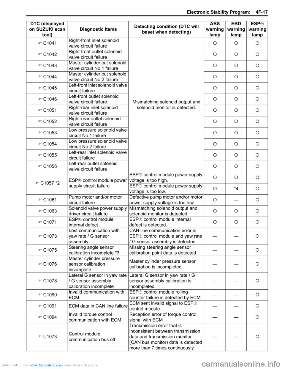
�) C1041 Right-front inlet solenoid
valve circuit failure
Mismatching solenoid output and solenoid monitor is detected. �{�{�{
�) C1042 Right-front outlet solenoid
valve circuit failure �{�{�{
�) C1043 Master cylinder cut solenoid
valve circuit No.1 failure �{�{�{
�) C1044 Master cylinder cut solenoid
valve circuit No.2 failure �{�{�{
�) C1045 Left-front inlet solenoid valve
circuit failure �{�{�{
�) C1046 Left-front outlet solenoid
valve circuit failure �{�{�{
�) C1051 Right-rear inlet solenoid
valve circuit failure �{�{�{
�) C1052 Right-rear outlet solenoid
valve circuit failure �{�{�{
�) C1053 Low pressure solenoid valve
circuit No.1 failure �{�{�{
�) C1054 Low pressure solenoid valve
circuit No.2 failure �{�{�{
�) C1055 Left-rear inlet solenoid valve
circuit failure �{�{�{
�) C1056 Left-rear outlet solenoid
valve circuit failure �{�{�{
�) C1057 *2 ESP
® control module power
supply circuit failure ESP®
control module power supply
voltage is too high. �{�{�{
ESP® control module power supply
voltage is too low. �{
*4 �{
�) C1061 Pump motor and/or motor
circuit failure Defective pump motor and/or motor
power supply voltage is too low.
�{
— �{
�) C1063 Solenoid valve
power supply
driver circuit failure Mismatching solenoid output and
solenoid monitor is detected.
�{�{�{
�) C1071 ESP
® con
trol module
internal defect ESP®
control module internal
defect is detected. �{�{�{
�) C1073 Lost communication with
yaw rate / G sensor
assembly CAN line communication error in
ESP®
control module and yaw rate
/ G sensor assembly is detected. ——
�{
�) C1075 Steering angle sensor
calibration incomplete *3 Missing steering angle sensor
calibration point data is detected.
——
�{
�) C1076 Master cylinder pressure
sensor calibration
incomplete Master cylinder pressure sensor
calibration is incompleted.
——
�{
�) C1078 Lateral G sensor in yaw rate
/ G sensor assembly
calibration incomplete Lateral G sensor in yaw rate / G
sensor assembly calibration is
incompleted.
——
�{
�) C1090 Invalid communication with
ECM ESP®
control module rolling
counter failure is detected by ECM. ——
�{
�) C1091 ECM data in CAN line failure ECM sent invalid signal to ESP
®
control module. ——
�{
�) C1094 Invalid torque control
communication with ECM Reception error of torque control
signal with ECM
——
�{
�) U1073 Control module
communication bus off Transmission error that is
inconsistent between transmission
data and transmission monitor
(CAN bus monitor) data is detected
more than 7 times continuously.
——
�{
DTC (displayed
on SUZUKI scan tool) Diagnostic Items
Detecting condition (DTC will
beset when detecting) ABS
warning lamp EBD
warning lamp ESP
®
warning lamp
Page 594 of 1496
Downloaded from www.Manualslib.com manuals search engine 4F-20 Electronic Stability Program:
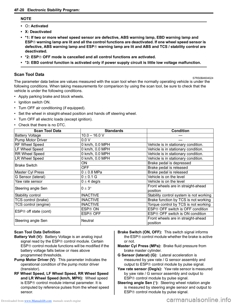
NOTE
•�{: Activated
• X: Deactivated
• *1: If two or more wheel speed sensor are defective, ABS warning lamp, EBD warning lamp and ESP ® warning lamp are lit and all the control functions are deactivated. If one wheel speed sensor is
defective, ABS warning lamp and ESP ® warning lamp are lit and ABS and TCS / stability control are
deactivated.
• *2: ESP ® OFF mode is cancelled and all control functions are activated.
• *3: EBD control function is activated only if po wer supply circuit is little low voltage malfunction.
Scan Tool DataS7RS0B4604024
The parameter data below are values measured with the scan tool when the normally operating vehicle is under the
following conditions. When taking measurements for comparis on by using the scan tool, be sure to check that the
vehicle is under the following conditions.
• Apply parking brake and block wheels.
• Ignition switch ON.
• Turn OFF air conditioning (if equipped).
• Set the wheel in straight-ahead position and hands off steering wheel.
• Turn OFF all electric loads (except ignition).
• Check that there is no DTC.
Scan Tool Data Definition
Battery Volt (V): Battery Voltage is an analog input
signal read by the ESP ® control module. Certain
ESP ® control module functions will be modified if the
battery voltage falls below or rises above
programmed thresholds.
Pump Motor Driver (V): This parameter indicates the
operational condition of the pump motor driver
(transistor).
RF Wheel Speed, LF Wheel Speed, RR Wheel Speed and LR Wheel Speed (km/h, MPH): Wheel speed
is ESP ® control module internal parameter. It is
computed by reference puls es from the wheel speed
sensor. Brake Switch (ON, OFF):
This switch signal informs
the ESP ® control module whether the brake is active
or not.
Master Cyl Press (MPa): Brake fluid pressure from
brake master cylinder.
G Sensor (lateral) (G): Lateral acceleration is
measured by yaw rate / G sensor assembly and
output to ESP ® control module by pulse signal.
Yaw rate sensor (Deg/s): Yaw rate sensor is measured
by yaw rate / G sensor assembly and output to
ESP® control module by pulse signal.
Steering angle Sen ( °): Steering wheel rotation angle
is measured by steering angle sensor and output to
ESP® control module by pulse signal.
Scan Tool Data Standards Condition
Battery Voltage 10.0 – 16.0 V —
Pump Motor Driver 0.0 V —
RF Wheel Speed 0 km/h, 0.0 MPH Veh icle is in stationary condition.
LF Wheel Speed 0 km/h, 0.0 MPH Veh icle is in stationary condition.
RR Wheel Speed 0 km/h, 0.0 MPH Vehic le is in stationary condition.
LR Wheel Speed 0 km/h, 0.0 MPH Veh icle is in stationary condition.
Brake Switch ON Brake pedal is depressed
OFF Brake pedal is released
Master Cyl Press 0 ± 0.8 MPa Brake pedal is released
G Sensor (lateral) 0 ± 0.1 G Vehicle is on the level
Yaw rate sensor 0 ± 4 deg/s Vehicle is on the level
Steering angle Sen 0 ± 3 ° Front wheels are in straight-ahead
position
Stability control INACTIVE Stability control system is not working
TCS control (brake) INACTIVE Brake function by TCS is not working
TCS control (engine) INACTIVE Torque control by TCS is not working
ESP ® off state (cont) ESP®
ON ESP
® OF
F switch is OFF condition
ESP® OFF ESP ® OFF switch is ON condition
Steering angle Sen Neutral Front wheels are in straight-ahead
position