body structure SUZUKI SWIFT 2006 2.G Service Workshop Manual
[x] Cancel search | Manufacturer: SUZUKI, Model Year: 2006, Model line: SWIFT, Model: SUZUKI SWIFT 2006 2.GPages: 1496, PDF Size: 34.44 MB
Page 4 of 1496

Downloaded from www.Manualslib.com manuals search engine 00
0
1
2
3
4
5
6
7
8
9
10
11
Vo l u m e 1
Precautions............................................................... 00-iPrecautions ............................................................ 00-1
General Information ................ ................................... 0-i
General Information ............................................... 0A-1
Maintenance and Lubricatio n ................................. 0B-1
Engine ......................................................................... 1-i Precautions .............................................................. 1-1
Engine General Information and Diagnosis ........... 1A-1
Aux. Emission Control Devices .............................. 1B-1
Engine Electrical Devices....................................... 1C-1
Engine Mechanical ................................................. 1D-1
Engine Lubrication System .................................... 1E-1
Engine Cooling System .......................................... 1F-1
Fuel System ...........................................................1G-1
Ignition System....................................................... 1H-1
Starting System ....................................................... 1I-1
Charging System.....................................................1J-1
Exhaust System ..................................................... 1K-1
Suspension ................................................................. 2-i Precautions .............................................................. 2-1
Suspension General Diagnosis .............................. 2A-1
Front Suspension ................................................... 2B-1
Rear Suspension................ .................................... 2C-1
Wheels and Tires ................................................... 2D-1
Driveline / Axle ........................................................... 3-i Precautions .............................................................. 3-1
Drive Shaft / Axle ................................................... 3A-1
Brakes ......................................................................... 4-i Precautions .............................................................. 4-1
Brake Control System and Diagnosis .................... 4A-1
Front Brakes........................................................... 4B-1
Rear Brakes ........................................................... 4C-1
Parking Brake......................................................... 4D-1
ABS ........................................................................ 4E-1
Electronic Stability Program ................................... 4F-1
Vo l u m e 2
Precautions ............................................................... 00-iPrecautions ............................................................ 00-1
Transmission / Transaxle .... ...................................... 5-i
Precautions .............................................................. 5-1
Automatic Transmission/Transaxle ........................ 5A-1
Manual Transmission/Transaxle ............................ 5B-1
Clutch .....................................................................5C-1
Steering ....................................................................... 6-i Precautions .............................................................. 6-1
Steering General Diagnosis ................................... 6A-1
Steering Wheel and Column .................................. 6B-1
Power Assisted Steering System ...........................6C-1
HVAC ........................................................................... 7-i Precautions .............................................................. 7-1
Heater and Ventilation............................................ 7A-1
Air Conditioning System ......................................... 7B-1
Restraint ...................................................................... 8-i Precautions .............................................................. 8-1
Seat Belts ............................................................... 8A-1
Air Bag System ...................................................... 8B-1
Body, Cab and Accessories .... .................................. 9-i
Precautions .............................................................. 9-1
Wiring Systems ...................................................... 9A-1
Lighting Systems .................................................... 9B-1
Instrumentation / Driver Info. / Horn .......................9C-1
Wipers / Washers ...................................................9D-1
Glass / Windows / Mirrors ...................................... 9E-1
Security and Locks ................................................. 9F-1
Seats ..................................................................... 9G-1
Interior Trim ............................................................9H-1
Hood / Fenders / Doors .......................................... 9J-1
Body Structure ....................................................... 9K-1
Paint / Coatings ...................................................... 9L-1
Exterior Trim .......................................................... 9M-1
Control Systems ....................................................... 10-i Precautions ............................................................ 10-1
Body Electrical Control Sy stem ............................ 10B-1
Immobilizer Control System .................................10C-1
Keyless Start System ........................................... 10E-1
TABLE OF CONTENTS
Page 456 of 1496
Downloaded from www.Manualslib.com manuals search engine 2C-2 Rear Suspension:
Repair Instructions
Rear Wheel Alignment InspectionS7RS0B2306017
Measure toe and camber referring to “Front Wheel
Alignment Inspection and Adjustment in Section 2B”.
NOTE
Rear suspension is not adjustable structure.
Rear toe (total)
: IN 3.8 ± 3.8 mm (IN 0.1969 ± 0.1969 in)
Rear camber
: –1 ° ± 1
If measured value is out of specified value, check
following items for damage, deformation and crack.
• Rear axle (torsion beam)
• Spindle, wheel hub or wheel bearing
• Vehicle body
Rear Shock Absorber Removal and InstallationS7RS0B2306001
Removal 1) Hoist vehicle and remove rear wheels.
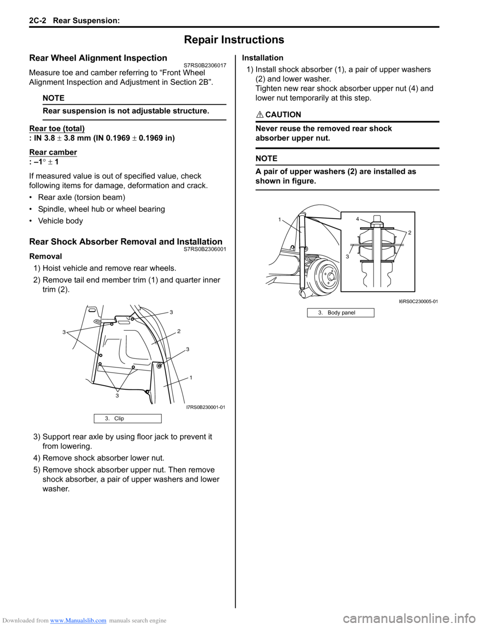
2) Remove tail end member trim (1) and quarter inner trim (2).
3) Support rear axle by using floor jack to prevent it from lowering.
4) Remove shock absorber lower nut.
5) Remove shock absorber upper nut. Then remove shock absorber, a pair of upper washers and lower
washer. Installation
1) Install shock absorber (1), a pair of upper washers (2) and lower washer.
Tighten new rear shock absorber upper nut (4) and
lower nut temporarily at this step.
CAUTION!
Never reuse the removed rear shock
absorber upper nut.
NOTE
A pair of upper washers (2) are installed as
shown in figure.
3. Clip
3
3 2
3
1
3
I7RS0B230001-01
3. Body panel
14
3 2
I6RS0C230005-01
Page 1148 of 1496
Downloaded from www.Manualslib.com manuals search engine 8B-110 Air Bag System:
Installation
CAUTION!
Proper operation of forward-sensor requires
sensor be rigidly attached to vehicle
structure and that the arrow on sensor be
pointing toward the front of the vehicle.
1) Check that none of the following faulty conditions exists.
• Bend, deformity or rust of front panel.
• Foreign matter on mating surface of sensor.
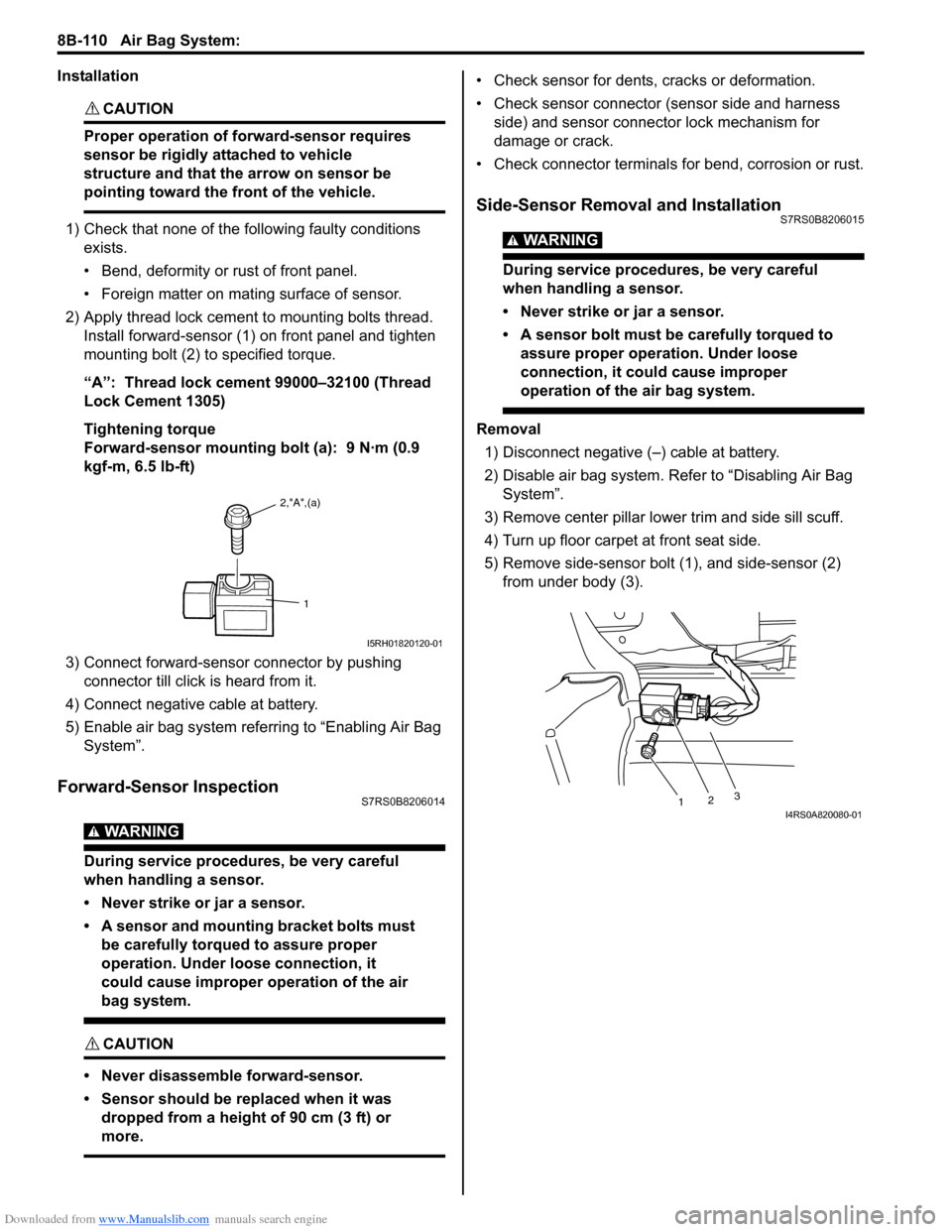
2) Apply thread lock cement to mounting bolts thread. Install forward-sensor (1) on front panel and tighten
mounting bolt (2) to specified torque.
“A”: Thread lock cement 99000–32100 (Thread
Lock Cement 1305)
Tightening torque
Forward-sensor mounting bolt (a): 9 N·m (0.9
kgf-m, 6.5 lb-ft)
3) Connect forward-sensor connector by pushing connector till click is heard from it.
4) Connect negative cable at battery.
5) Enable air bag system referring to “Enabling Air Bag System”.
Forward-Sensor InspectionS7RS0B8206014
WARNING!
During service procedures, be very careful
when handling a sensor.
• Never strike or jar a sensor.
• A sensor and mounting bracket bolts must be carefully torqued to assure proper
operation. Under loose connection, it
could cause improper operation of the air
bag system.
CAUTION!
• Never disassemble forward-sensor.
• Sensor should be replaced when it was dropped from a height of 90 cm (3 ft) or
more.
• Check sensor for dents, cracks or deformation.
• Check sensor connector (sensor side and harness side) and sensor connector lock mechanism for
damage or crack.
• Check connector terminals for bend, corrosion or rust.
Side-Sensor Removal and InstallationS7RS0B8206015
WARNING!
During service procedures, be very careful
when handling a sensor.
• Never strike or jar a sensor.
• A sensor bolt must be carefully torqued to assure proper operation. Under loose
connection, it could cause improper
operation of the air bag system.
Removal
1) Disconnect negative (–) cable at battery.
2) Disable air bag system. Re fer to “Disabling Air Bag
System”.
3) Remove center pillar lowe r trim and side sill scuff.
4) Turn up floor carpet at front seat side.
5) Remove side-sensor bolt (1), and side-sensor (2) from under body (3).
2,"A",(a)
1
I5RH01820120-01
1 23I4RS0A820080-01
Page 1170 of 1496

Downloaded from www.Manualslib.com manuals search engine 9-iv Table of Contents
Rear End Door Opener System Symptom Diagnosis .......................................................... 9F-5
Rear End Door Opener System Operation Inspection .......................................................... 9F-5
Repair Instructions ........... ................................... 9F-6
Front Door Lock Assembly Components ............ 9F-6
Front Door Lock Assembly Removal and Installation ......................................................... 9F-6
Front Door Lock Assembly Inspection ................ 9F-8
Power Door Lock Switch In spection.................... 9F-8
Door Key Cylinder Switch Inspection .................. 9F-8
Power Door Lock Actuator Inspection ................. 9F-9
Rear Door Lock Assembly Components ........... 9F-10
Rear Door Lock Assembly Removal and Installation ....................................................... 9F-10
Rear Door Lock Assembly Inspection ............... 9F-10
Rear End Door Lock Assembly Components.... 9F-11
Rear End Door Lock Assembly Removal and Installation ....................................................... 9F-11
Rear End Door Lock Assembly Inspection........ 9F-12
Rear End Door Opener Switch Inspection ........ 9F-12
Replacement of Transmitte r Battery ................. 9F-13
Programming Transmitter Code for Keyless Entry System (Vehicle without Keyless Start
System) ........................................................... 9F-13
Keyless Entry Answer Back Function
Change-over Procedure (If Equipped) ............ 9F-14
Keyless Entry Receiver Removal and
Installation ....................................................... 9F-14
Keyless Entry Receiver and Its Circuit Inspection ........................................................ 9F-15
Specifications .... ................................................. 9F-16
Tightening Torque Specifications ...................... 9F-16
Special Tools and Equipmen t ........................... 9F-16
Recommended Service Material ....................... 9F-16
Seats ............. ............................................ 9G-1
Repair Instructions ............................................. 9G-1
Front Seat Components ..................................... 9G-1
Front Seat Removal and In stallation .................. 9G-2
Rear Seat Components...................................... 9G-3
Rear Seat Removal and Installation................... 9G-4
Specifications .... .................................................. 9G-4
Tightening Torque Specifications ....................... 9G-4
Special Tools and Equipmen t ............................ 9G-4
Recommended Service Material ........................ 9G-4
Interior Trim ................. ............................ 9H-1
Repair Instructions ............ ..................................9H-1
Floor Carpet Removal and Installation ................9H-1
Head Lining Removal and Installation.................9H-1
Console Box Components ..................................9H-2
Specifications ..................... ..................................9H-3
Tightening Torque Specifications ........................9H-3
Hood / Fenders / Doors ...... ...................... 9J-1
Repair Instructions ............ .................................. 9J-1
Hood Removal and Installation ........................... 9J-1
Hood Inspection and Adjustment ........................ 9J-1
Front Fender Components .................................. 9J-2
Front Fender Removal and Installation ............... 9J-2
Front Door Assembly Comp onents ..................... 9J-3
Front Door Assembly Removal and Installation ......................................................... 9J-3
Rear Door Assembly Components...................... 9J-5
Rear Door Assembly Removal and Installation ......................................................... 9J-5
Rear End Door Assembly Components .............. 9J-6
Rear End Door Assembly Removal and Installation ......................................................... 9J-6
Specifications ..................... .................................. 9J-8
Tightening Torque Specifications ........................ 9J-8
Special Tools and Equipmen t ............................. 9J-8
Recommended Service Material ......................... 9J-8
Body Structure............... .......................... 9K-1
Repair Instructions ............ ..................................9K-1
Front Bumper and Rear Bumper Components .... 9K-1
Cowl Top Components........................................ 9K-2
Specifications ..................... ..................................9K-3
Body Dimensions ................................................ 9K-3
Panel Clearance................................................ 9K-10
Paint / Coatings ............. ...........................9L-1
General Description ............................................. 9L-1
Anti-Corrosion Treatment Construction............... 9L-1
Plastic Parts Finishing ......................................... 9L-2
Component Location ............ ............................... 9L-3
Sealant Application Areas ................................... 9L-3
Under Coating Application Areas ........................ 9L-8
Anti-Corrosion Compound Application Area ..... 9L-10
Exterior Trim ...... ...................................... 9M-1
Repair Instructions ......... .................................... 9M-1
Roof Molding Components................................. 9M-1
Splash Guard (If Equipped) Components .......... 9M-2
Page 1378 of 1496
Downloaded from www.Manualslib.com manuals search engine 9K-1 Body Structure:
Body, Cab and Accessories
Body Structure
Repair Instructions
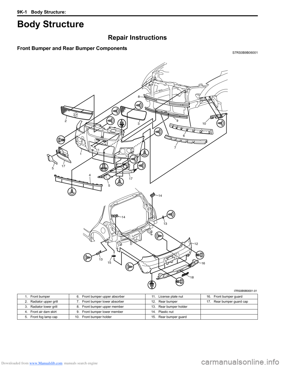
Front Bumper and Rear Bumper ComponentsS7RS0B9B06001
10
6
79
8
32
1
5
4 1117
175
1315
14
12
16
18
14
13
I7RS0B9B0001-01
1. Front bumper
6. Front bumper upper absorber 11. License plate nut16. Front bumper guard
2. Radiator upper grill 7. Front bumper lower absorber 12. Rear bumper17. Rear bumper guard cap
3. Radiator lower grill 8. Front bumper upper member 13. Rear bumper holder
4. Front air dam skirt 9. Front bumper lower member 14. Plastic nut
5. Front fog lamp cap 10. Front bumper holder 15. Rear bumper guard
Page 1379 of 1496

Downloaded from www.Manualslib.com manuals search engine Body Structure: 9K-2
Cowl Top ComponentsS7RS0B9B06002
1. Cowl top cover 3. Cowl top side garnish 5. Hood rear seal
2. Cowl top cover lid 4. Cowl top panel
“A”
“A”
“A”
“A”
5
1
2 3
4
I4RS0B9B0002-02
Page 1380 of 1496
Downloaded from www.Manualslib.com manuals search engine 9K-3 Body Structure:
Specifications
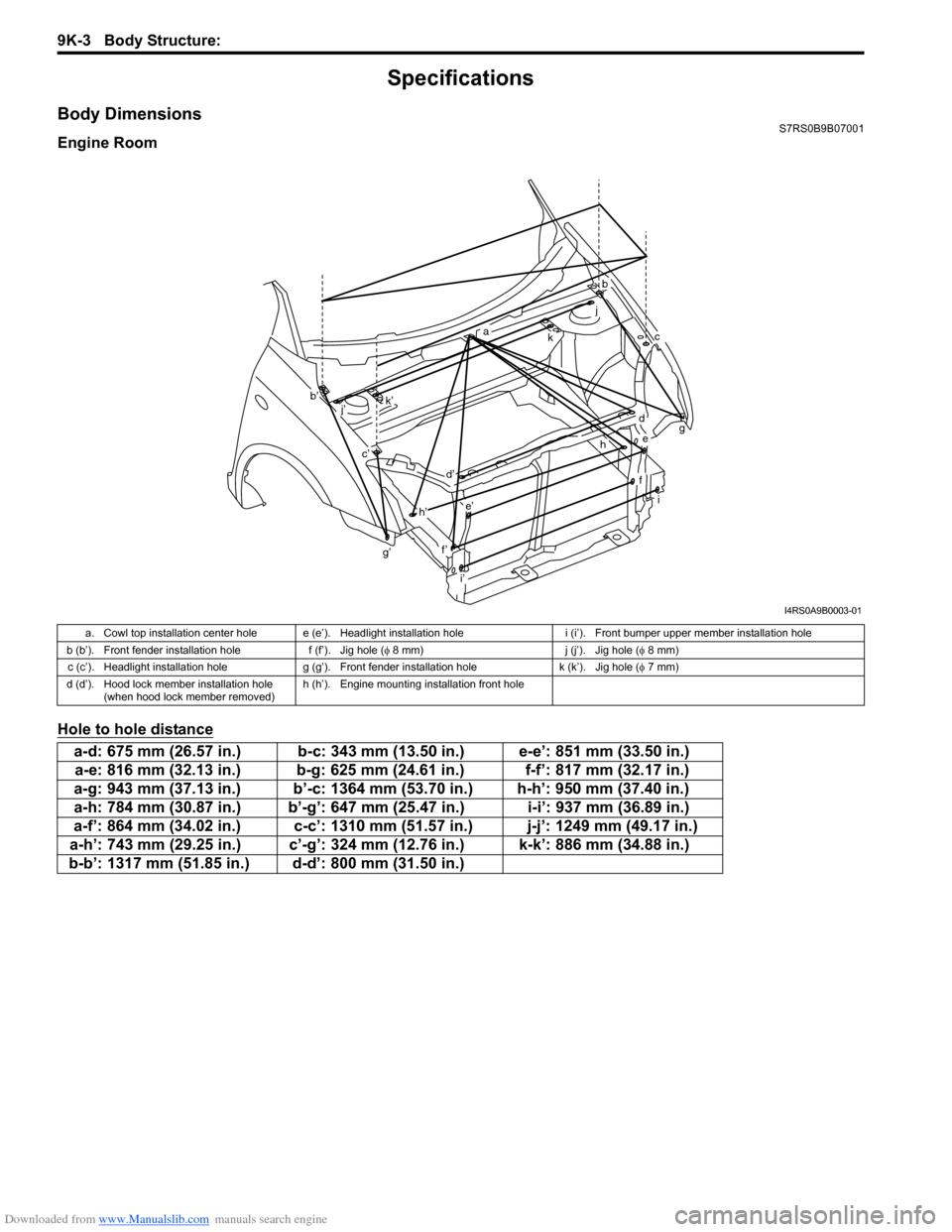
Body DimensionsS7RS0B9B07001
Engine Room
Hole to hole distance
g’
b
ckg
i
a
b’
c’
d
d’
e
e’
f’
f
h
h’
i’ j
k’
j’
I4RS0A9B0003-01
a. Cowl top installation center hole e (e’). Headlight installation hole i (i’). Front bumper upper member installation hole
b (b’). Front fender installation hole f (f’). Jig hole (φ 8 mm) j (j’). Jig hole (φ 8 mm)
c (c’). Headlight installation hole g (g’). Front fender installation hole k (k’). Jig hole (φ 7 mm)
d (d’). Hood lock member installation hole (when hood lock member removed) h (h’). Engine mounting installation front hole
a-d: 675 mm (26.57 in.) b-c: 343 mm (13.50 in.) e-e’: 851 mm (33.50 in.)
a-e: 816 mm (32.13 in.) b-g: 625 mm (24.61 in.) f-f’: 817 mm (32.17 in.)
a-g: 943 mm (37.13 in.) b’-c: 1364 mm (53.70 in.) h-h’: 950 mm (37.40 in.)
a-h: 784 mm (30.87 in.) b’-g’: 647 mm (25.47 in.) i-i’: 937 mm (36.89 in.)
a-f’: 864 mm (34.02 in.) c-c’: 1310 mm (51.57 in.) j-j’: 1249 mm (49.17 in.)
a-h’: 743 mm (29.25 in.) c’-g’: 324 mm (12.76 in.) k-k’: 886 mm (34.88 in.)
b-b’: 1317 mm (51.85 in.) d-d’: 800 mm (31.50 in.)
Page 1381 of 1496
Downloaded from www.Manualslib.com manuals search engine Body Structure: 9K-4
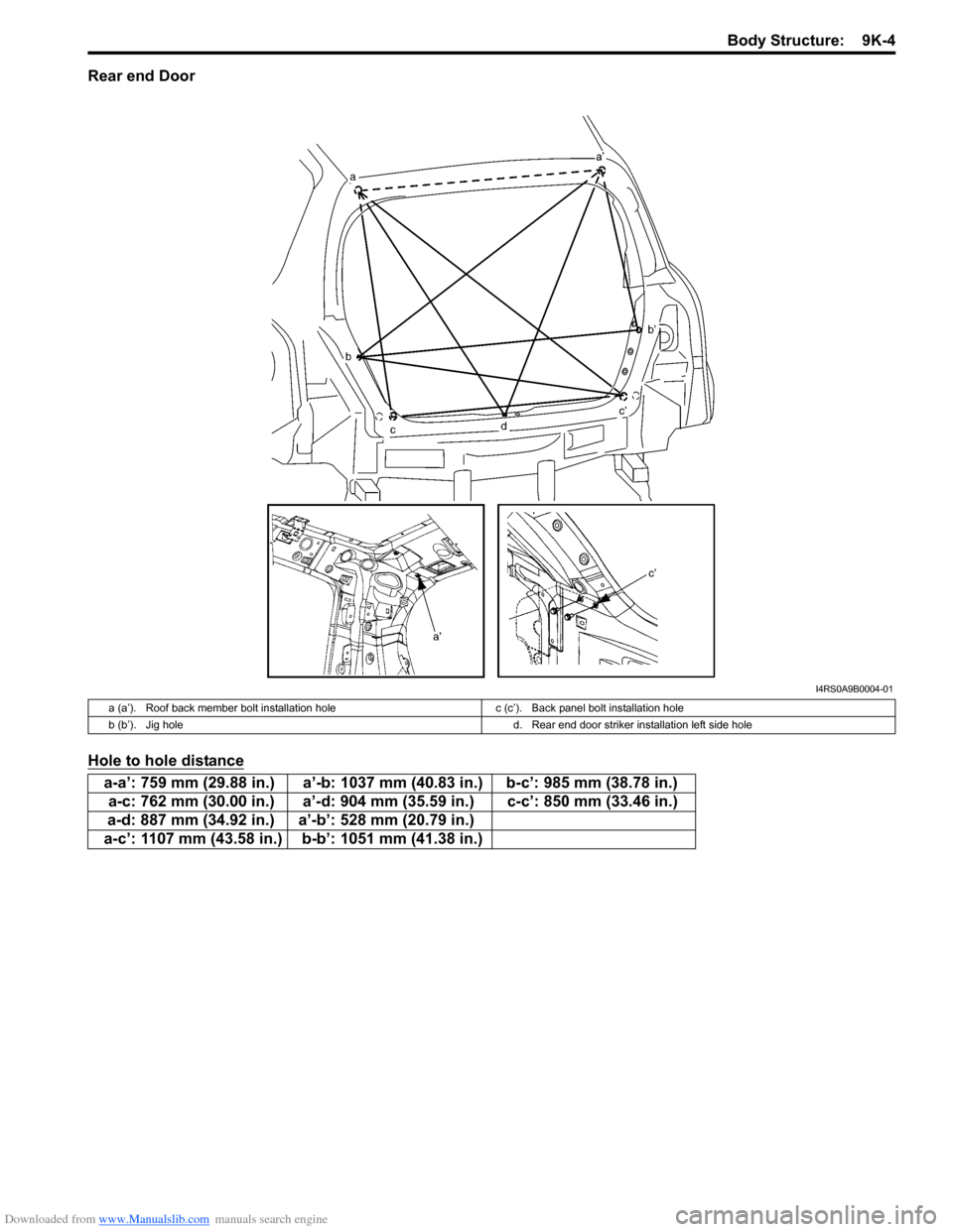
Rear end Door
Hole to hole distance
I4RS0A9B0004-01
a (a’). Roof back member bolt installation holec (c’). Back panel bolt installation hole
b (b’). Jig hole d. Rear end door striker installation left side hole
a-a’: 759 mm (29.88 in.) a’-b: 1037 mm (40.83 in.) b-c’: 985 mm (38.78 in.)
a-c: 762 mm (30.00 in.) a’-d: 904 mm (35.59 in.) c-c’: 850 mm (33.46 in.)
a-d: 887 mm (34.92 in.) a’-b’: 528 mm (20.79 in.)
a-c’: 1107 mm (43.58 in.) b-b’: 1051 mm (41.38 in.)
Page 1382 of 1496

Downloaded from www.Manualslib.com manuals search engine 9K-5 Body Structure:
Side Body
Hole to hole distance
Hole to hole distance
I4RS0A9B0005-02
a (a’). Jig hole (φ 8 mm) e (e’). Rear door lower hinge installation rear hole i (i’). Jig hole ( φ 10 mm)
b (b’). Front door upper hinge installation upper hole f (f’). Rear door upper hinge installation upper hole j (j’). Rear door switc h installation hole (large hole)
c (c’). Front door lower hinge installation lower hole g (g’). Jig hole ( φ 10 mm) k (k’). Rear side sill scuff installation hole
d (d’). Bleeding hole h (h’). Curtain air bag clip installation hole
a-d: 1055 mm (41.54 in.) c-e: 1021 mm (40.20 in.) f-j: 835 mm (32.87 in.) a-f: 747 mm (29.41 in.) c-f: 1123 mm (44.21 in.) h-i: 601 mm (23.66 in.)
a-g: 378 mm (14.88 in.) d-g: 1129 mm (44.45 in.) h-j: 817 mm (32.17 in.)
b-c: 383 mm (15.08 in.) e-f: 354 mm (13.94 in.) h-k: 1097 mm (43.19 in.)
b-e: 1085 mm (42.72 in.) e-j: 946 mm (37.24 in.) i-k: 1153 mm (45.39 in.) b-f: 1061 mm (41.77 in.) f-i: 926 mm (36.46 in.)
a-a’: 1039 mm (40.91 in.) e-e’: 1474 mm (58.03 in.) i-i’: 1009 mm (39.72 in.)
b-b’: 1461 mm (57.52 in.) f-f’: 1468 mm (57.80 in.) j-j’: 1327 mm (52.24 in.) c-c’: 1489 mm (58.62 in.) g-g’: 1018 mm (40.08 in.) k-k’: 1472 mm (57.95 in.)
d-d’: 1472 mm (57.95 in.) h-h’: 1022 mm (40.24 in.)
Page 1383 of 1496
Downloaded from www.Manualslib.com manuals search engine Body Structure: 9K-6
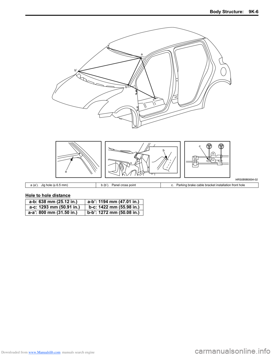
Hole to hole distance
a
cb
a’
a
bc
b’
I4RS0B9B0004-02
a (a’). Jig hole (φ 6.5 mm) b (b’). Panel cross point c. Parking brake cable bracket installation front hole
a-b: 638 mm (25.12 in.) a-b’: 1194 mm (47.01 in.)
a-c: 1293 mm (50.91 in.) b-c: 1422 mm (55.98 in.)
a-a’: 800 mm (31.50 in.) b-b’: 1272 mm (50.08 in.)