generator main bolt SUZUKI SWIFT 2006 2.G Service Workshop Manual
[x] Cancel search | Manufacturer: SUZUKI, Model Year: 2006, Model line: SWIFT, Model: SUZUKI SWIFT 2006 2.GPages: 1496, PDF Size: 34.44 MB
Page 33 of 1496

Downloaded from www.Manualslib.com manuals search engine Maintenance and Lubrication: 0B-3
NOTE
тАв тАЬIтАЭ: Inspect and correct or replace if necessary
тАв тАЬRтАЭ: Replace or change
тАв *1: Inspect or replace more frequently if the vehicle is used under dusty conditions.
тАв *2: Clean or replace more frequently if the air from the air conditioning decreases.
Repair Instructions
Accessory Drive Belt InspectionS7RS0B0206001
WARNING!
All inspection and replacement are to be
performed with ENGINE NOT RUNNING.
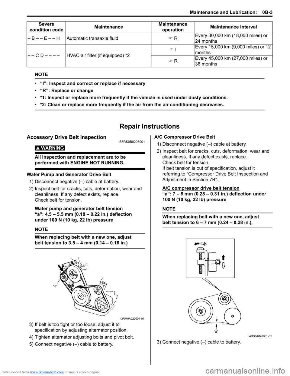
Water Pump and Generator Drive Belt1) Disconnect negative (тАУ) cable at battery.
2) Inspect belt for cracks, cu ts, deformation, wear and
cleanliness. If any defect exists, replace.
Check belt for tension.
Water pump and generator belt tension
тАЬaтАЭ: 4.5 тАУ 5.5 mm (0.18 тАУ 0.22 in.) deflection
under 100 N (10 kg, 22 lb) pressure
NOTE
When replacing belt with a new one, adjust
belt tension to 3.5 тАУ 4 mm (0.14 тАУ 0.16 in.)
3) If belt is too tight or too loose, adjust it to
specification by adjusting alternator position.
4) Tighten alternator adjusting bolts and pivot bolt.
5) Connect negative (тАУ) cable to battery. A/C Compressor Drive Belt
1) Disconnect negative (тАУ) cable at battery.
2) Inspect belt for cracks, cuts, deformation, wear and cleanliness. If any defect exists, replace.
Check belt for tension.
If belt tension is out of specification, adjust it
referring to тАЬCompressor Dr ive Belt Inspection and
Adjustment in Section 7BтАЭ.
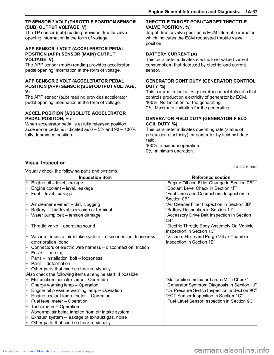
A/C compressor drive belt tension
тАЬaтАЭ: 7 тАУ 8 mm (0.28 тАУ 0.31 in.) deflection under
100 N (10 kg, 22 lb) pressure
NOTE
When replacing belt with a new one, adjust
belt tension to 6 тАУ 7 mm (0.24 тАУ 0.28 in.).
3) Connect negative (тАУ) cable to battery.
тАУ B тАУ тАУ E тАУ тАУ H Automatic transaxle fluid
�) R Every 30,000 km (18,000 miles) or
24 months
тАУ тАУ C D тАУ тАУ тАУ тАУ HVAC air filter (if equipped) *2 �)
I Every 15,000 km (9,000 miles) or 12
months
�) R Every 45,000 km (27,000 miles) or
36 months
Severe
condition code MaintenanceMaintenance
operation Maintenance interval
I3RM0A020001-01
I4RS0A020001-01
Page 87 of 1496

Downloaded from www.Manualslib.com manuals search engine Engine General Information and Diagnosis: 1A-37
TP SENSOR 2 VOLT (THROTTLE POSITION SENSOR
(SUB) OUTPUT VOLTAGE, V)
The TP sensor (sub) reading provides throttle valve
opening information in the form of voltage.
APP SENSOR 1 VOLT (ACCELERATOR PEDAL
POSITION (APP) SENSOR (MAIN) OUTPUT
VOLTAGE, V)
The APP sensor (main) read ing provides accelerator
pedal opening information in the form of voltage.
APP SENSOR 2 VOLT (ACCELERATOR PEDAL
POSITION (APP) SENSOR (S UB) OUTPUT VOLTAGE,
V)
The APP sensor (sub) reading provides accelerator
pedal opening information in the form of voltage.
ACCEL POSITION (ABSOLUTE ACCELERATOR
PEDAL POSITION, %)
When accelerator pedal is at fully released position,
accelerator pedal is indicated as 0 тАУ 5% and 90 тАУ 100%
fully depressed position. THROTTLE TARGET POSI (TARGET THROTTLE
VALVE POSITION, %)
Target throttle valve position is ECM internal parameter
which indicates the ECM requested throttle valve
position.
BATTERY CURRENT (A)
This parameter indicates elec
tric load value (current
consumption) that detected by electric load current
sensor.
GENERATOR CONT DUTY (GENERATOR CONTROL
DUTY, %)
This parameter indicates generator control duty ratio that
controls production electricity of generator by ECM.
100%: No limitation for the generating
0%: Maximum limitation for the generating
GENERATOR FIELD DUTY (GENERATOR FIELD
COIL DUTY, %)
This parameter indicates ope rating rate (status of
production electricity) for gen erator by field coil duty
ratio.
100%: maximum operation.
0%: minimum operation.
Visual InspectionS7RS0B1104008
Visually check the following parts and systems.
Inspection item Reference section
тАв Engine oil тАУ level, leakage тАЬEngine Oil and Filter Change in Section 0BтАЭ
тАв Engine coolant тАУ level, leakage тАЬCo olant Level Check in Section 1FтАЭ
тАв Fuel тАУ level, leakage тАЬFuel Lines and Connections Inspection in Section 0BтАЭ
тАв Air cleaner element тАУ dirt, clogging тАЬAir Cleaner Filter Inspection in Section 0BтАЭ
тАв Battery тАУ fluid level, corrosion of terminal тАЬBattery Description in Section 1JтАЭ
тАв Water pump belt тАУ tension damage тАЬAccessory Drive Belt Inspection in Section 0BтАЭ
тАв Throttle valve тАУ operating sound тАЬElectric Throttle Body Assembly On-Vehicle Inspection in Section 1CтАЭ
тАв Vacuum hoses of air intake system тАУ disconnection, looseness,
deterioration, bend тАЬVacuum Hose and Purge Valve Chamber
Inspection in Section 1BтАЭ
тАв Connectors of electric wire harness тАУ disconnection, friction
тАв Fuses тАУ burning
тАв Parts тАУ installation, bolt тАУ looseness
тАв Parts тАУ deformation
тАв Other parts that can be checked visually
Also check the following items at engine start, if possible
тАв Malfunction indicator lamp тАУ Operation тАЬMalfunction Indicator Lamp (MIL) CheckтАЭ
тАв Charge warning lamp тАУ Operation тАЬGenera tor Symptom Diagnosis in Section 1JтАЭ
тАв Engine oil pressure warning lamp тАУ Operation тАЬO il Pressure Switch Inspection in Section 9CтАЭ
тАв Engine coolant temp. meter тАУ Operation тАЬECT Sensor Inspection in Section 1CтАЭ
тАв Fuel level meter тАУ Operation тАЬFuel Level Sensor Inspection in Section 9CтАЭ
тАв Tachometer тАУ Operation
тАв Abnormal air being inhaled from air intake system
тАв Exhaust system тАУ leakage of exhaust gas, noise
тАв Other parts that can be checked visually
Page 285 of 1496

Downloaded from www.Manualslib.com manuals search engine Engine Electrical Devices: 1C-13
Without Using SUZUKI Scan Tool1) Measure sensor voltage between тАЬC37-23тАЭ terminal of ECM connector and vehicle body ground referring
to тАЬInspection of ECM and Its Circuits in Section 1AтАЭ.
If check result is satisfactory, electric load current
sensor is in good condition.
If check result is not satisfactory, check the following
parts and circuit.
тАв Electric load current sensor circuit (power, ground and output)
тАв Following charging system components тАУ Battery (refer to тАЬBattery Inspection in Section
1JтАЭ)
тАУ Generator (refer to тАЬGenerator Inspection in Section 1JтАЭ)
тАУ Generator output control circuit (refer to тАЬGenerator Test (Undercharged Battery Check)
in Section 1JтАЭ)
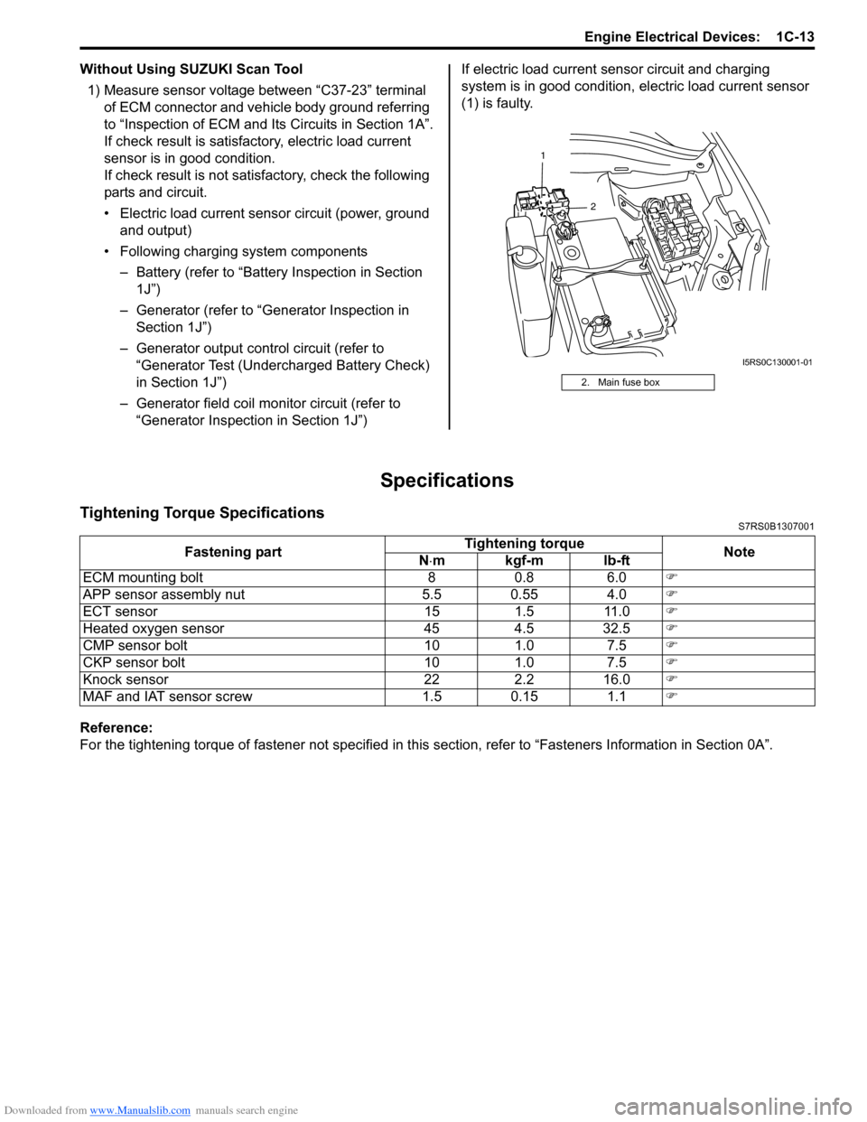
тАУ Generator field coil monitor circuit (refer to тАЬGenerator Inspection in Section 1JтАЭ) If electric load current sensor circuit and charging
system is in good condition,
electric load current sensor
(1) is faulty.
Specifications
Tightening Torque SpecificationsS7RS0B1307001
Reference:
For the tightening torque of fastener not specified in this section, refer to тАЬFasteners Information in Section 0AтАЭ.
2. Main fuse box
2
1
I5RS0C130001-01
Fastening part
Tightening torque
Note
N тЛЕmkgf-mlb-ft
ECM mounting bolt 8 0.8 6.0 �)
APP sensor assembly nut 5.5 0.55 4.0 �)
ECT sensor 15 1.5 11.0 �)
Heated oxygen sensor 45 4.5 32.5 �)
CMP sensor bolt 10 1.0 7.5 �)
CKP sensor bolt 10 1.0 7.5 �)
Knock sensor 22 2.2 16.0 �)
MAF and IAT sensor screw 1.5 0.15 1.1 �)
Page 349 of 1496

Downloaded from www.Manualslib.com manuals search engine Engine Mechanical: 1D-64
Honing or Reboring Cylinders1) When any cylinder needs reboring, all other cylinders must also be rebored at the same time.
2) Select oversized piston according to amount of cylinder wear.
Oversize piston specification
Oversize 0.50: 78.453 тАУ 78.468 mm (3.0887 тАУ
3.0893 in.)
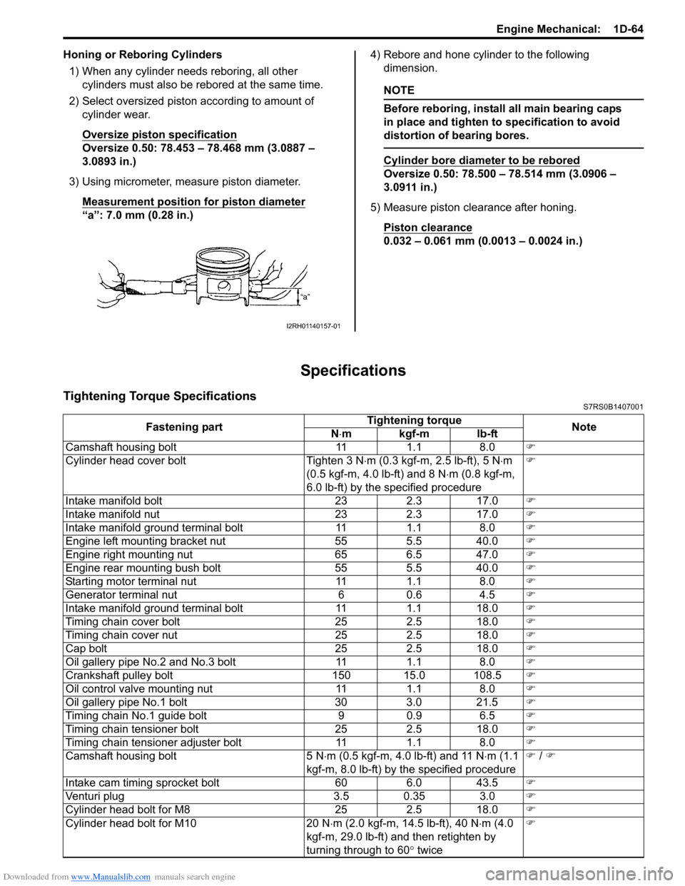
3) Using micrometer, measure piston diameter. Measurement position for piston diameter
тАЬaтАЭ: 7.0 mm (0.28 in.) 4) Rebore and hone cylinder to the following
dimension.
NOTE
Before reboring, install all main bearing caps
in place and tighten to specification to avoid
distortion of bearing bores.
Cylinder bore diameter to be rebored
Oversize 0.50: 78.500 тАУ 78.514 mm (3.0906 тАУ
3.0911 in.)
5) Measure piston clearance after honing. Piston clearance
0.032 тАУ 0.061 mm (0.0013 тАУ 0.0024 in.)
Specifications
Tightening Torque SpecificationsS7RS0B1407001
I2RH01140157-01
Fastening part Tightening torque
Note
N тЛЕmkgf-mlb-ft
Camshaft housing bolt 11 1.1 8.0 �)
Cylinder head cover bolt Tighten 3 N тЛЕm (0.3 kgf-m, 2.5 lb-ft), 5 N тЛЕm
(0.5 kgf-m, 4.0 lb-ft) and 8 N тЛЕm (0.8 kgf-m,
6.0 lb-ft) by the specified procedure �)
Intake manifold bolt 23 2.3 17.0 �)
Intake manifold nut 23 2.3 17.0 �)
Intake manifold ground terminal bolt 11 1.1 8.0 �)
Engine left mounting bracket nut 55 5.5 40.0 �)
Engine right mounting nut 65 6.5 47.0 �)
Engine rear mounting bush bolt 55 5.5 40.0 �)
Starting motor terminal nut 11 1.1 8.0 �)
Generator terminal nut 6 0.6 4.5 �)
Intake manifold ground terminal bolt 11 1.1 18.0 �)
Timing chain cover bolt 25 2.5 18.0 �)
Timing chain cover nut 25 2.5 18.0 �)
Cap bolt 25 2.5 18.0 �)
Oil gallery pipe No.2 and No.3 bolt 11 1.1 8.0 �)
Crankshaft pulley bolt 150 15.0 108.5 �)
Oil control valve mounting nut 11 1.1 8.0 �)
Oil gallery pipe No.1 bolt 30 3.0 21.5 �)
Timing chain No.1 guide bolt 9 0.9 6.5 �)
Timing chain tensioner bolt 25 2.5 18.0 �)
Timing chain tensioner adjuster bolt 11 1.1 8.0 �)
Camshaft housing bolt 5 N тЛЕm (0.5 kgf-m, 4.0 lb-ft) and 11 N тЛЕm (1.1
kgf-m, 8.0 lb-ft) by the specified procedure �)
/ �)
Intake cam timing sprocket bolt 60 6.0 43.5 �)
Venturi plug 3.5 0.35 3.0 �)
Cylinder head bolt for M8 25 2.5 18.0 �)
Cylinder head bolt for M10 20 N тЛЕm (2.0 kgf-m, 14.5 lb-ft), 40 N тЛЕm (4.0
kgf-m, 29.0 lb-ft) and then retighten by
turning through to 60 ┬░ twice �)
Page 662 of 1496

Downloaded from www.Manualslib.com manuals search engine 5A-18 Automatic Transmission/Transaxle:
Visual InspectionS7RS0B5104002
Visually check the following parts and systems.
Malfunction Indicator Lamp (MIL) CheckS7RS0B5104003
Refer to the same item in тАЬMalfunction Indicator Lam p (MIL) Check in Section 1AтАЭ for checking procedure.
Transmission Warning Light CheckS7RS0B5104004
1) Turn ignition switch ON.
2) Check that transmission warning light lights for about 2 тАУ 4 sec. and then goes OFF.
If anything faulty is found, advance тАЬTransmission Warn ing Light Circuit Check тАУ Light Does Not Come тАЬONтАЭ at
Ignition Switch ONтАЭ or тАЬTransmission Warning Light Circu it Check тАУ Light Remains тАЬONтАЭ at Ignition Switch ONтАЭ.
Inspection item Referring
тАв A/T fluid ----- level, leakage, color тАЬAutomatic Transaxle Fluid Level Inspection in Section 0BтАЭ
тАв A/T fluid hoses ----- disconnection, looseness, deterioration тАЬA/T Fluid Cooler Hoses ReplacementтАЭ
тАв A/T select cable ----- installation тАЬS elect Cable Removal and InstallationтАЭ
тАв Engine oil ----- level, leakage тАЬEngine Oil and Filter Change in Section 0BтАЭ
тАв Engine coolant ----- level, leakage тАЬEngine Coolant Change in Section 0BтАЭ
тАв Engine mountings ----- play, looseness, damage тАЬEngine Assembly Removal and Installation in Section 1DтАЭ
тАв Suspension ----- play, looseness тАЬSuspension, Wheels and Tires Symptom Diagnosis in Section 2AтАЭ
тАв Drive shafts ----- damage тАЬFront Drive Shaft Assembly On-Vehicle Inspection in Section 3AтАЭ
тАв Battery ----- indicator condition, corrosion of terminal тАЬBattery Inspection in Section 1JтАЭ
тАв Connectors of electric wire harness ----- disconnection, friction тАЬElectronic Shift Control System Components
LocationтАЭ
тАв Fuses ----- burning
тАв Parts ----- installation, damage
тАв Bolts ----- looseness
тАв Other parts that can be checked visually
Also check the following items at engine start, if possible.
тАв Transmission warning light (if equipped) ----- Operation тАЬTransmission Warning Light CheckтАЭ
тАв Malfunction indicator lamp ----- Operation тАЬMalfunction Indicator Lamp (MIL) CheckтАЭ
тАв Charge warning lamp ----- Operation тАЬGenerator Symptom Diagnosis in Section 1JтАЭ
тАв Engine oil pressure warning lamp ----- Operation тАЬOil Pressure Warning Ligh t Symptom Diagnosis in
Section 9CтАЭ
тАв Engine coolant temp. meter ----- Operation тАЬEngine Coolant Temperature (ECT) Meter
Symptom Diagnosis in Section 9CтАЭ
тАв Other parts that can be checked visually
I4RS0A510008-01