torque control arm SUZUKI SWIFT 2006 2.G Service Workshop Manual
[x] Cancel search | Manufacturer: SUZUKI, Model Year: 2006, Model line: SWIFT, Model: SUZUKI SWIFT 2006 2.GPages: 1496, PDF Size: 34.44 MB
Page 23 of 1496
Downloaded from www.Manualslib.com manuals search engine General Information: 0A-2
SAS: Steering Angle Sensor
SDM: Sensing and Diagnostic Module (Air Bag Controller, Air bag Control Module)
SDT: Smart Diagnostic Tester
SFI: Sequential Multipor t Fuel Injection
SOHC: Single Over Head Camshaft
T:
TBI: Throttle Body Fuel Injection (Single-Point Fuel
Injection, SPI)
TCC: Torque Converter Clutch
TCM: Transmission Control Module (A/T Controller, A/T
Control Module)
TDC: Top Dead Center
TP Sensor: Throttle Position Sensor TVV:
Thermal Vacuum Valve (Thermal Vacuum
Switching Valve, TVSV, Bi metal Vacuum Switching
Valve, BVSV)
TWC: Three Way Catalytic Converter (Three Way
Catalyst)
2WD: 2 Wheel Drive
U:
USB: Universal Serial Bus
V:
VIN: Vehicle Identification Number
VSS: Vehicle Speed Sensor
VVT: Variable Valve Timing (Camshaft Position Control)
W:
WU-OC: Warm Up Oxidation Catalytic Converter
WU-TWC: Warm Up Three Way Catalytic Converter
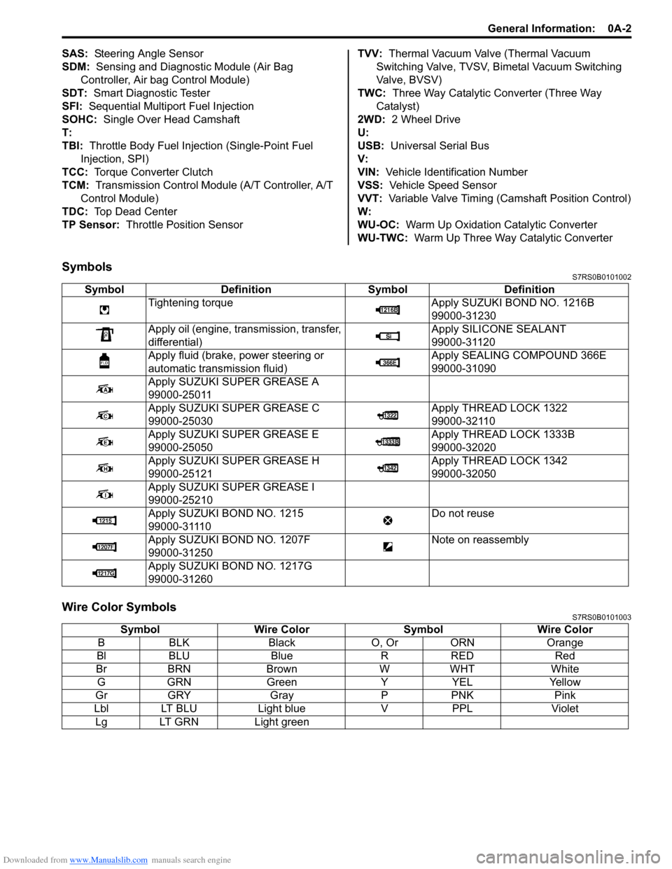
SymbolsS7RS0B0101002
Wire Color SymbolsS7RS0B0101003
Symbol Definition SymbolDefinition
Tightening torque Apply SUZUKI BOND NO. 1216B
99000-31230
Apply oil (engine, transmission, transfer,
differential) Apply SILICONE SEALANT
99000-31120
Apply fluid (brake, power steering or
automatic transmission fluid) Apply SEALING COMPOUND 366E
99000-31090
Apply SUZUKI SUPER GREASE A
99000-25011
Apply SUZUKI SUPER GREASE C
99000-25030 Apply THREAD LOCK 1322
99000-32110
Apply SUZUKI SUPER GREASE E
99000-25050 Apply THREAD LOCK 1333B
99000-32020
Apply SUZUKI SUPER GREASE H
99000-25121 Apply THREAD LOCK 1342
99000-32050
Apply SUZUKI SUPER GREASE I
99000-25210
Apply SUZUKI BOND NO. 1215
99000-31110 Do not reuse
Apply SUZUKI BO ND NO. 1207F
99000-31250 Note on reassembly
Apply SUZUKI BO ND NO. 1217G
99000-31260
Symbol Wire Color SymbolWire Color
B BLK Black O, Or ORN Orange
Bl BLU Blue RRED Red
Br BRN Brown WWHT White
G GRN Green YYEL Yellow
Gr GRY Gray PPNK Pink
Lbl LT BLU Light blueVPPL Violet
Lg LT GRN Light green
Page 289 of 1496
Downloaded from www.Manualslib.com manuals search engine Engine Mechanical: 1D-4
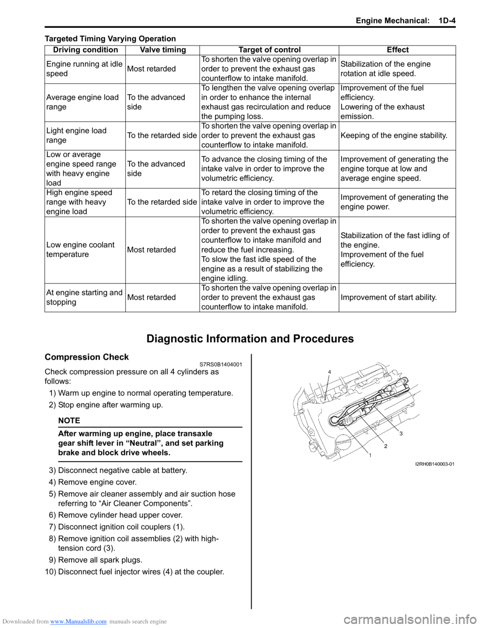
Targeted Timing Varying Operation
Diagnostic Information and Procedures
Compression CheckS7RS0B1404001
Check compression pressure on all 4 cylinders as
follows:
1) Warm up engine to normal operating temperature.
2) Stop engine after warming up.
NOTE
After warming up engine, place transaxle
gear shift lever in “Neutral”, and set parking
brake and block drive wheels.
3) Disconnect negative cable at battery.
4) Remove engine cover.
5) Remove air cleaner assembly and air suction hose referring to “Air Cleaner Components”.
6) Remove cylinder head upper cover.
7) Disconnect ignition coil couplers (1).
8) Remove ignition coil assemblies (2) with high- tension cord (3).
9) Remove all spark plugs.
10) Disconnect fuel injector wires (4) at the coupler. Driving condition Valve timing Target of control Effect
Engine running at idle
speed Most retardedTo shorten the valve opening overlap in
order to prevent the exhaust gas
counterflow to in
take manifold. Stabilization of the engine
rotation at idle speed.
Average engine load
range To the advanced
sideTo lengthen the valve opening overlap
in order to enhance the internal
exhaust gas recirculation and reduce
the pumping loss. Improvement of the fuel
efficiency.
Lowering of the exhaust
emission.
Light engine load
range To the retarded sideTo shorten the valve opening overlap in
order to prevent the exhaust gas
counterflow to in
take manifold. Keeping of the engine stability.
Low or average
engine speed range
with heavy engine
load To the advanced
side
To advance the closing timing of the
intake valve in order to improve the
volumetric efficiency. Improvement of generating the
engine torque at low and
average engine speed.
High engine speed
range with heavy
engine load To the retarded sideTo retard the closing timing of the
intake valve in order to improve the
volumetric efficiency. Improvement of generating the
engine power.
Low engine coolant
temperature Most retardedTo shorten the valve opening overlap in
order to prevent the exhaust gas
counterflow to intake manifold and
reduce the fuel increasing.
To slow the fast idle speed of the
engine as a result of stabilizing the
engine idling. Stabilization of the fast idling of
the engine.
Improvement of the fuel
efficiency.
At engine starting and
stopping Most retardedTo shorten the valve opening overlap in
order to prevent the exhaust gas
counterflow to in
take manifold. Improvement of start ability.I2RH0B140003-01
Page 403 of 1496
Downloaded from www.Manualslib.com manuals search engine Starting System: 1I-2
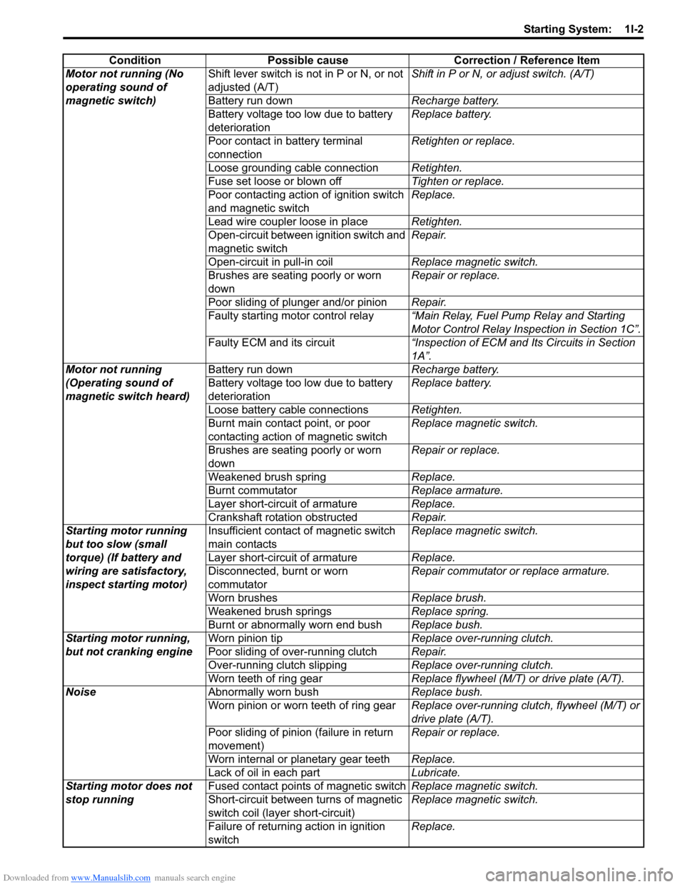
ConditionPossible cause Correction / Reference Item
Motor not running (No
operating sound of
magnetic switch) Shift lever switch is not in P or N, or not
adjusted (A/T)
Shift in P or N, or
adjust switch. (A/T)
Battery run down Recharge battery.
Battery voltage too low due to battery
deterioration Replace battery.
Poor contact in battery terminal
connection Retighten or replace.
Loose grounding cable connection Retighten.
Fuse set loose or blown off Tighten or replace.
Poor contacting action of ignition switch
and magnetic switch Replace.
Lead wire coupler loose in place Retighten.
Open-circuit between ignition switch and
magnetic switch Repair.
Open-circuit in pull-in coil Replace magnetic switch.
Brushes are seating poorly or worn
down Repair or replace.
Poor sliding of plunger and/or pinion Repair.
Faulty starting motor control relay “Main Relay, Fuel Pump Relay and Starting
Motor Control Relay Inspection in Section 1C”.
Faulty ECM and its circuit “Inspection of ECM and Its Circuits in Section
1A”.
Motor not running
(Operating sound of
magnetic switch heard) Battery run down
Recharge battery.
Battery voltage too low due to battery
deterioration Replace battery.
Loose battery cable connections Retighten.
Burnt main contact point, or poor
contacting action of magnetic switch Replace magnetic switch.
Brushes are seating poorly or worn
down Repair or replace.
Weakened brush spring Replace.
Burnt commutator Replace armature.
Layer short-circuit of armature Replace.
Crankshaft rotation obstructed Repair.
Starting motor running
but too slow (small
torque) (If battery and
wiring are satisfactory,
inspect starting motor) Insufficient contact
of magnetic switch
main contacts Replace magnetic switch.
Layer short-circuit of armature Replace.
Disconnected, burnt or worn
commutator Repair commutator or replace armature.
Worn brushes Replace brush.
Weakened brush springs Replace spring.
Burnt or abnormally worn end bush Replace bush.
Starting motor running,
but not cranking engine Worn pinion tip
Replace over-running clutch.
Poor sliding of over-running clutch Repair.
Over-running clutch slipping Replace over-running clutch.
Worn teeth of ring gear Replace flywheel (M/T) or drive plate (A/T).
Noise Abnormally worn bush Replace bush.
Worn pinion or worn teeth of ring gear Replace over-running clutch, flywheel (M/T) or
drive plate (A/T).
Poor sliding of pinion (failure in return
movement) Repair or replace.
Worn internal or planetary gear teeth Replace.
Lack of oil in each part Lubricate.
Starting motor does not
stop running Fused contact points of magnetic switch
Replace magnetic switch.
Short-circuit between turns of magnetic
switch coil (layer short-circuit) Replace magnetic switch.
Failure of returning action in ignition
switch Replace.
Page 429 of 1496
Downloaded from www.Manualslib.com manuals search engine Table of Contents 2- i
2
Section 2
CONTENTS
Suspension
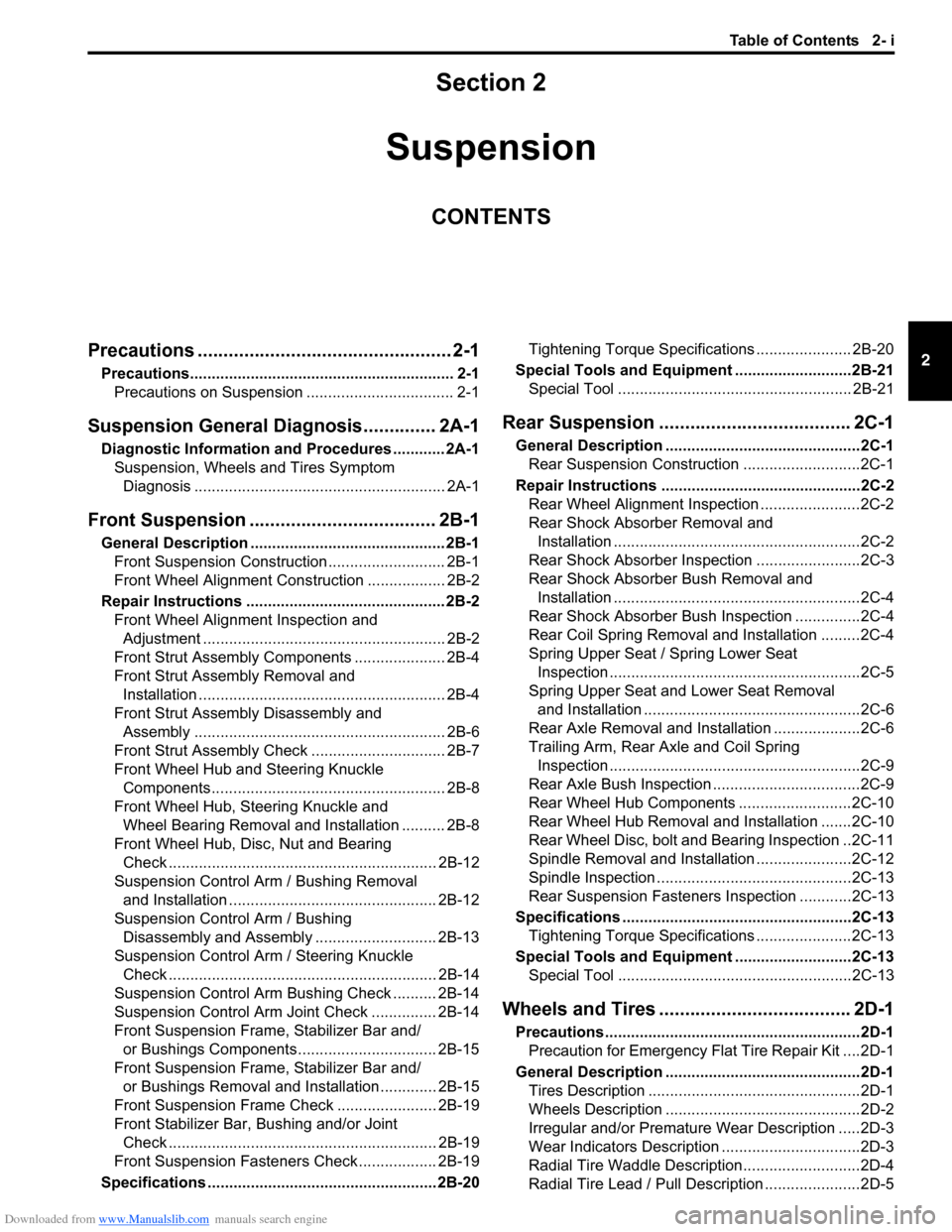
Precautions ................................................. 2-1
Precautions............................................................. 2-1
Precautions on Suspension .................................. 2-1
Suspension General Dia gnosis.............. 2A-1
Diagnostic Information and Procedures ............ 2A-1
Suspension, Wheels and Tires Symptom Diagnosis .......................................................... 2A-1
Front Suspension ........... ......................... 2B-1
General Description ............................................. 2B-1
Front Suspension Construction ........................... 2B-1
Front Wheel Alignment Cons truction .................. 2B-2
Repair Instructions .............................................. 2B-2 Front Wheel Alignment Inspection and Adjustment ........................................................ 2B-2
Front Strut Assembly Comp onents ..................... 2B-4
Front Strut Assembly Removal and Installation ......................................................... 2B-4
Front Strut Assembly Disassembly and Assembly .......................................................... 2B-6
Front Strut Assembly Chec k ............................... 2B-7
Front Wheel Hub and Steering Knuckle Components...................................................... 2B-8
Front Wheel Hub, Steering Knuckle and Wheel Bearing Removal and Installation .......... 2B-8
Front Wheel Hub, Disc, Nut and Bearing Check .............................................................. 2B-12
Suspension Control Arm / Bushing Removal and Installation ................................................ 2B-12
Suspension Control Arm / Bushing Disassembly and Assembly ............................ 2B-13
Suspension Control Arm / Steering Knuckle Check .............................................................. 2B-14
Suspension Control Arm Bushing Check .......... 2B-14
Suspension Control Arm Joint Check ............... 2B-14
Front Suspension Fram e, Stabilizer Bar and/
or Bushings Components................................ 2B-15
Front Suspension Fram e, Stabilizer Bar and/
or Bushings Removal and Installation ............. 2B-15
Front Suspension Frame Ch eck ....................... 2B-19
Front Stabilizer Bar, Bushing and/or Joint Check .............................................................. 2B-19
Front Suspension Fastener s Check .................. 2B-19
Specifications ..................................................... 2B-20 Tightening Torque Specifications ...................... 2B-20
Special Tools and Equipmen t ...........................2B-21
Special Tool ...................................................... 2B-21
Rear Suspension ............ ......................... 2C-1
General Description .............................................2C-1
Rear Suspension Construction ...........................2C-1
Repair Instructions ........... ...................................2C-2
Rear Wheel Alignment Inspection .......................2C-2
Rear Shock Absorber Removal and Installation .........................................................2C-2
Rear Shock Absorber Ins pection ........................2C-3
Rear Shock Absorber Bush Removal and Installation .........................................................2C-4
Rear Shock Absorber Bush Inspection ...............2C-4
Rear Coil Spring Removal and Installation .........2C-4
Spring Upper Seat / Spring Lower Seat Inspection ..........................................................2C-5
Spring Upper Seat and Lower Seat Removal and Installation ..................................................2C-6
Rear Axle Removal and Inst allation ....................2C-6
Trailing Arm, Rear Axle and Coil Spring Inspection ..........................................................2C-9
Rear Axle Bush Inspection ..................................2C-9
Rear Wheel Hub Components ..........................2C-10
Rear Wheel Hub Removal an d Installation .......2C-10
Rear Wheel Disc, bolt and Bearing Inspection ..2C-11
Spindle Removal and Installation ......................2C-12
Spindle Inspection .............................................2C-13
Rear Suspension Fasteners Inspection ............2C-13
Specifications .................... .................................2C-13
Tightening Torque Specifications ......................2C-13
Special Tools and Equipmen t ...........................2C-13
Special Tool ......................................................2C-13
Wheels and Tires ............ ......................... 2D-1
Precautions...........................................................2D-1
Precaution for Emergency Flat Tire Repair Kit ....2D-1
General Description .............................................2D-1 Tires Description .................................................2D-1
Wheels Description .............................................2D-2
Irregular and/or Premature Wear Description .....2D-3
Wear Indicators Description ................................2D-3
Radial Tire Waddle Description...........................2D-4
Radial Tire Lead / Pull Description ......................2D-5
Page 436 of 1496
Downloaded from www.Manualslib.com manuals search engine 2B-3 Front Suspension:
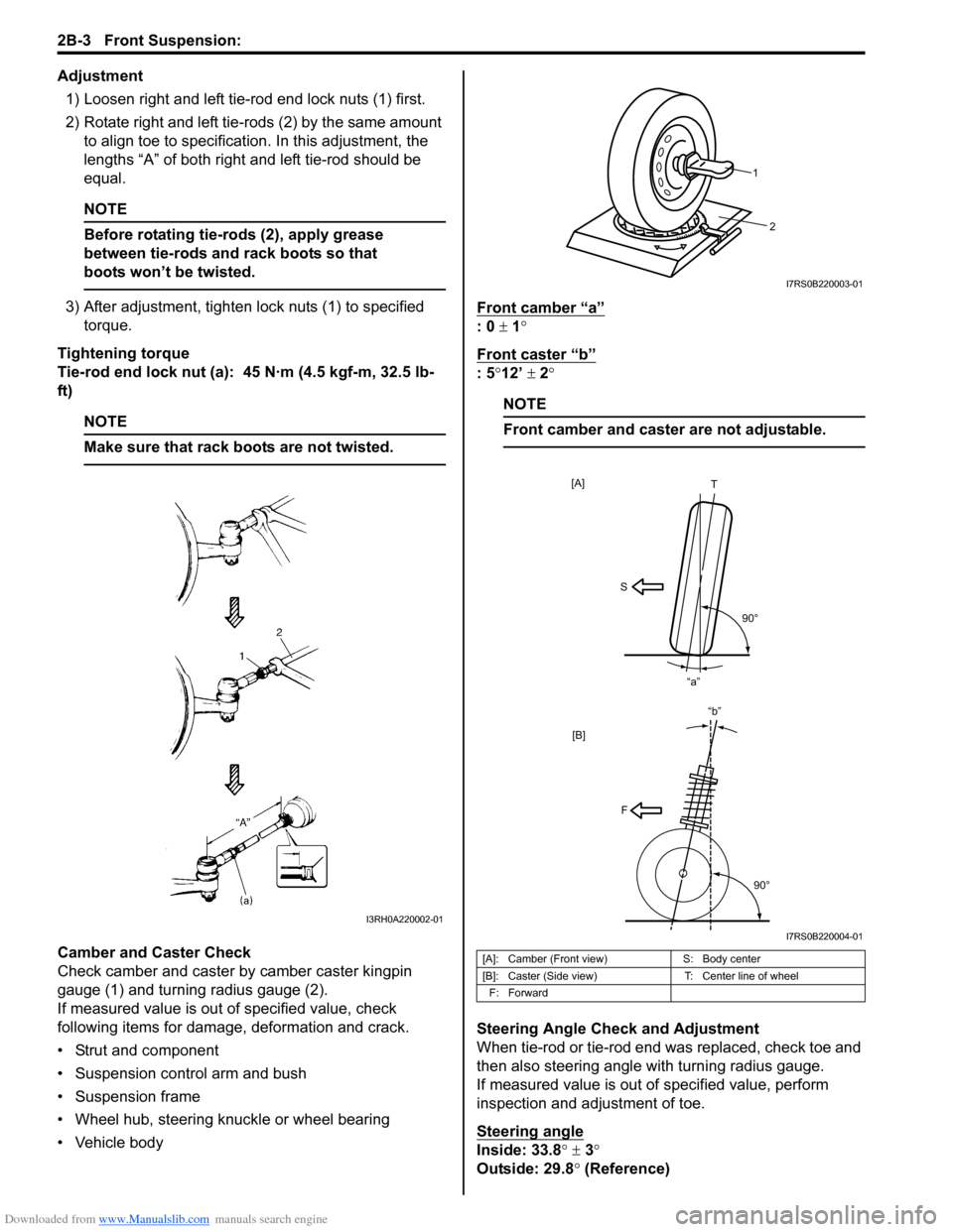
Adjustment1) Loosen right and left tie-rod end lock nuts (1) first.
2) Rotate right and left tie-rods (2) by the same amount to align toe to specification. In this adjustment, the
lengths “A” of both right and left tie-rod should be
equal.
NOTE
Before rotating tie-rods (2), apply grease
between tie-rods and rack boots so that
boots won’t be twisted.
3) After adjustment, tighten lock nuts (1) to specified torque.
Tightening torque
Tie-rod end lock nut (a): 45 N·m (4.5 kgf-m, 32.5 lb-
ft)
NOTE
Make sure that rack boots are not twisted.
Camber and Caster Check
Check camber and caster by camber caster kingpin
gauge (1) and turning radius gauge (2).
If measured value is out of specified value, check
following items for damage, deformation and crack.
• Strut and component
• Suspension control arm and bush
• Suspension frame
• Wheel hub, steering knuckle or wheel bearing
• Vehicle body Front camber “a”
: 0
± 1°
Front caster “b”
: 5 °12’ ± 2°
NOTE
Front camber and caster are not adjustable.
Steering Angle Check and Adjustment
When tie-rod or tie-rod end was replaced, check toe and
then also steering angle with turning radius gauge.
If measured value is out of specified value, perform
inspection and adjustment of toe.
Steering angle
Inside: 33.8 ° ± 3 °
Outside: 29.8 ° (Reference)
I3RH0A220002-01
[A]: Camber (Front view) S: Body center
[B]: Caster (Side view) T: Center line of wheel
F: Forward
2
1
I7RS0B220003-01
[B]
S T
90°
“a”
[A]
F
90°
“b”
I7RS0B220004-01
Page 444 of 1496
Downloaded from www.Manualslib.com manuals search engine 2B-11 Front Suspension:
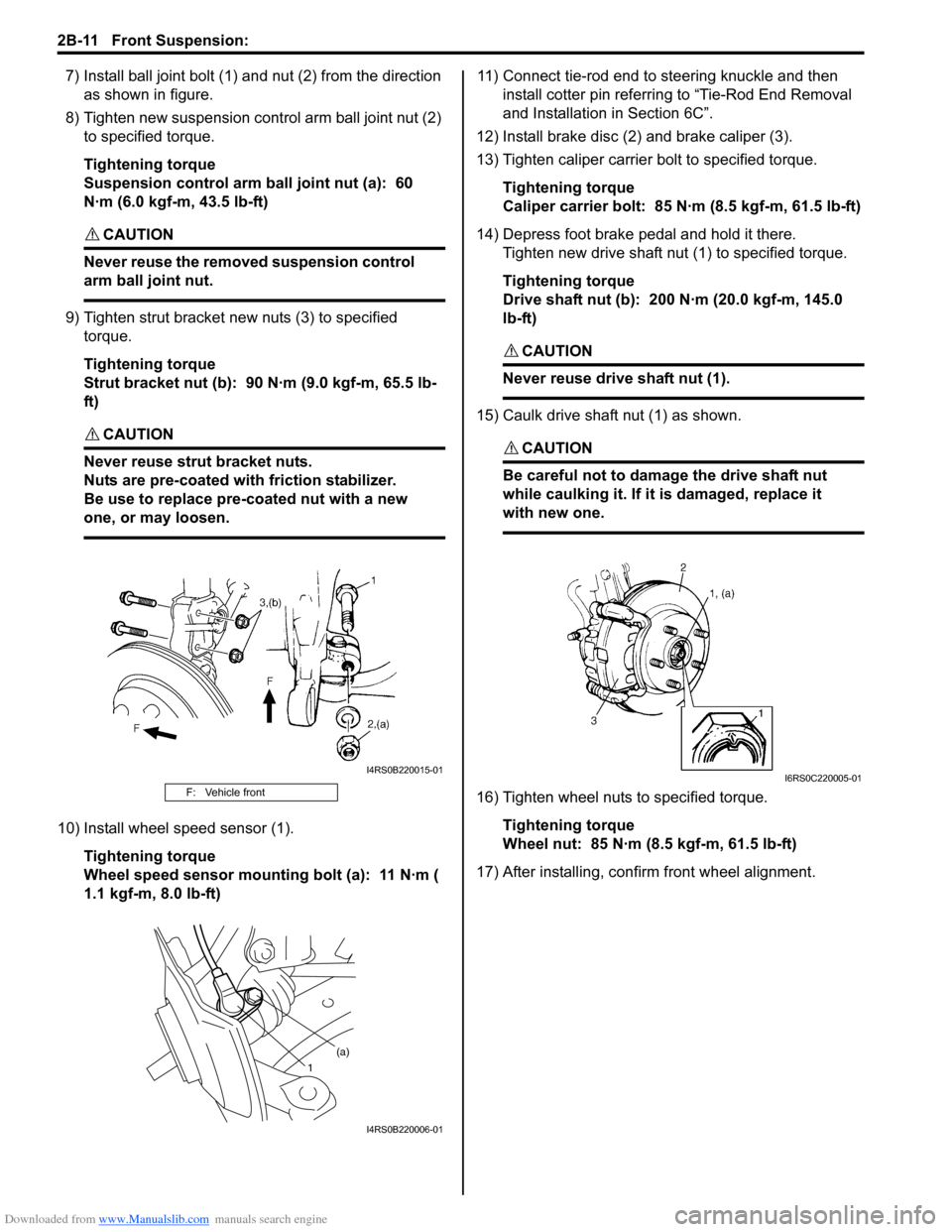
7) Install ball joint bolt (1) and nut (2) from the direction
as shown in figure.
8) Tighten new suspension co ntrol arm ball joint nut (2)
to specified torque.
Tightening torque
Suspension control arm ball joint nut (a): 60
N·m (6.0 kgf-m, 43.5 lb-ft)
CAUTION!
Never reuse the removed suspension control
arm ball joint nut.
9) Tighten strut bracket new nuts (3) to specified torque.
Tightening torque
Strut bracket nut (b): 90 N·m (9.0 kgf-m, 65.5 lb-
ft)
CAUTION!
Never reuse strut bracket nuts.
Nuts are pre-coated with friction stabilizer.
Be use to replace pre-coated nut with a new
one, or may loosen.
10) Install wheel speed sensor (1).
Tightening torque
Wheel speed sensor mounting bolt (a): 11 N·m (
1.1 kgf-m, 8.0 lb-ft) 11) Connect tie-rod end to steering knuckle and then
install cotter pin referrin g to “Tie-Rod End Removal
and Installation in Section 6C”.
12) Install brake disc (2) and brake caliper (3).
13) Tighten caliper carrier bolt to specified torque.
Tightening torque
Caliper carrier bolt: 85 N·m (8.5 kgf-m, 61.5 lb-ft)
14) Depress foot brake pedal and hold it there. Tighten new drive shaft nut (1) to specified torque.
Tightening torque
Drive shaft nut (b): 200 N·m (20.0 kgf-m, 145.0
lb-ft)
CAUTION!
Never reuse drive shaft nut (1).
15) Caulk drive shaft nut (1) as shown.
CAUTION!
Be careful not to damage the drive shaft nut
while caulking it. If it is damaged, replace it
with new one.
16) Tighten wheel nuts to specified torque.
Tightening torque
Wheel nut: 85 N·m (8.5 kgf-m, 61.5 lb-ft)
17) After installing, confirm front wheel alignment.F: Vehicle front
I4RS0B220015-01
1 (a)
I4RS0B220006-01
I6RS0C220005-01
Page 445 of 1496
Downloaded from www.Manualslib.com manuals search engine Front Suspension: 2B-12
Front Wheel Hub, Disc, Nut and Bearing CheckS7RS0B2206008
• Inspect each wheel disc for dents, distortion and cracks.
A disc in badly damaged condition must be replaced.
• Check rust of installation face inside of wheel disc.
As rust affects adversely, remove it thoroughly.
• Check wheel nuts for tightness and, as necessary, retighten them to specification.
• Check wheel bolt press-fitted into wheel hub for wear, damage, poor thread condition, and looseness.
Replace defective bolt with a new one.
When bolt installation is found loose, replace both bolt
and wheel hub with new ones.
Tightening torque
Wheel nut: 85 N·m (8.5 kgf-m, 61.5 lb-ft)
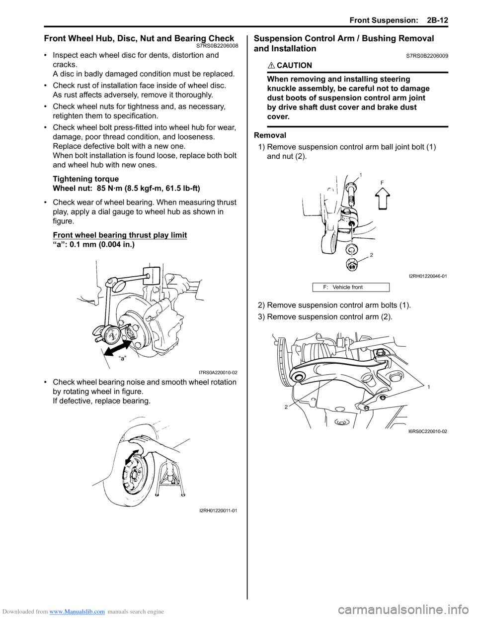
• Check wear of wheel bearing. When measuring thrust play, apply a dial gauge to wheel hub as shown in
figure.
Front wheel bearing thrust play limit
“a”: 0.1 mm (0.004 in.)
• Check wheel bearing noise and smooth wheel rotation by rotating wheel in figure.
If defective, replace bearing.
Suspension Control Arm / Bushing Removal
and Installation
S7RS0B2206009
CAUTION!
When removing and installing steering
knuckle assembly, be ca reful not to damage
dust boots of suspension control arm joint
by drive shaft dust cover and brake dust
cover.
Removal
1) Remove suspension contro l arm ball joint bolt (1)
and nut (2).
2) Remove suspension control arm bolts (1).
3) Remove suspension control arm (2).
I7RS0A220010-02
I2RH01220011-01
F: Vehicle front
I2RH01220046-01
1
2
I6RS0C220010-02
Page 446 of 1496
Downloaded from www.Manualslib.com manuals search engine 2B-13 Front Suspension:
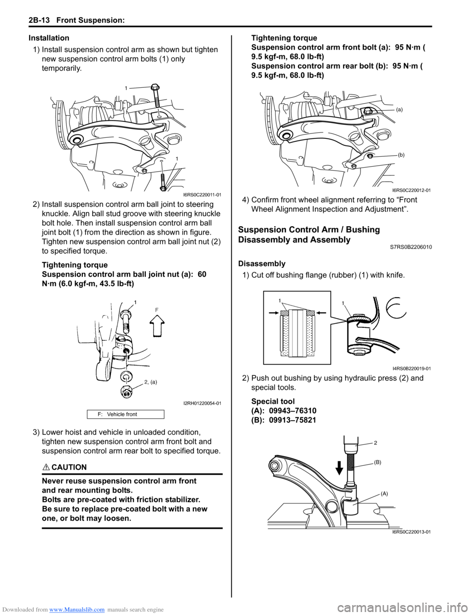
Installation1) Install suspension control arm as shown but tighten new suspension contro l arm bolts (1) only
temporarily.
2) Install suspensi on control arm ball joint to steering
knuckle. Align ball stud gr oove with steering knuckle
bolt hole. Then install su spension control arm ball
joint bolt (1) from the direction as shown in figure.
Tighten new suspension cont rol arm ball joint nut (2)
to specified torque.
Tightening torque
Suspension control arm ball joint nut (a): 60
N·m (6.0 kgf-m, 43.5 lb-ft)
3) Lower hoist and vehicle in unloaded condition, tighten new suspension control arm front bolt and
suspension control arm rear bolt to specified torque.
CAUTION!
Never reuse suspension control arm front
and rear mounting bolts.
Bolts are pre-coated with friction stabilizer.
Be sure to replace pre-coated bolt with a new
one, or bolt may loosen.
Tightening torque
Suspension control arm front bolt (a): 95 N·m (
9.5 kgf-m, 68.0 lb-ft)
Suspension control arm re ar bolt (b): 95 N·m (
9.5 kgf-m, 68.0 lb-ft)
4) Confirm front wheel alignment referring to “Front Wheel Alignment Inspection and Adjustment”.
Suspension Control Arm / Bushing
Disassembly and Assembly
S7RS0B2206010
Disassembly
1) Cut off bushing flange (rubber) (1) with knife.
2) Push out bushing by using hydraulic press (2) and special tools.
Special tool
(A): 09943–76310
(B): 09913–75821
F: Vehicle front
1
1
I6RS0C220011-01
I2RH01220054-01
(a)(b)
I6RS0C220012-01
I4RS0B220019-01
2
(A)
(B)
I6RS0C220013-01
Page 449 of 1496
Downloaded from www.Manualslib.com manuals search engine Front Suspension: 2B-16
4) Hoist vehicle and remove both wheels referring to “Wheel Removal and Installation in Section 2D”.
5) Remove cotter pins and tie-rod end nuts, and then disconnect both tie-rod ends from steering knuckles
referring to “Tie-Rod End Re moval and Installation in
Section 6C”.
6) Disconnect couplers of torque sensor and P/S motor.
7) Remove suspension control arm referring to “Suspension Control Arm / Bushing Removal and
Installation”.
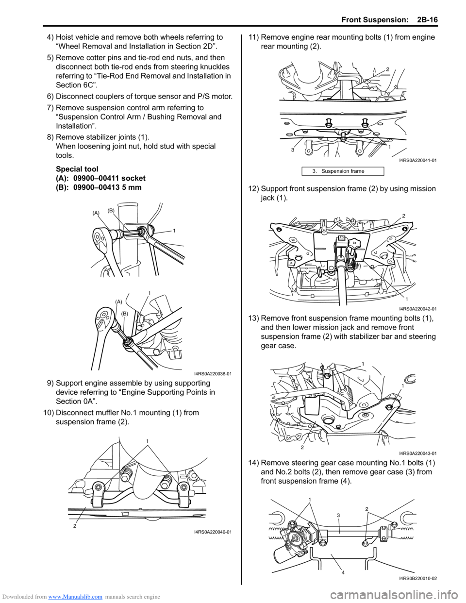
8) Remove stabilizer joints (1). When loosening joint nu t, hold stud with special
tools.
Special tool
(A): 09900–00411 socket
(B): 09900–00413 5 mm
9) Support engine assemble by using supporting device referring to “Engine Supporting Points in
Section 0A”.
10) Disconnect muffler No.1 mounting (1) from suspension frame (2). 11) Remove engine rear mounting bolts (1) from engine
rear mounting (2).
12) Support front suspension frame (2) by using mission jack (1).
13) Remove front suspension frame mounting bolts (1), and then lower mission jack and remove front
suspension frame (2) with st abilizer bar and steering
gear case.
14) Remove steering gear case mounting No.1 bolts (1) and No.2 bolts (2), then remove gear case (3) from
front suspensio n frame (4).
11
(A)
(A)
(B)
(B)
I4RS0A220038-01
1
2
I4RS0A220040-01
3. Suspension frame
2
3 1
I4RS0A220041-01
2
1
I4RS0A220042-01
1
2 1
I4RS0A220043-01
1
3
4 2
I4RS0B220010-02
Page 452 of 1496
Downloaded from www.Manualslib.com manuals search engine 2B-19 Front Suspension:
13) Install suspension control arm referring to
“Suspension Control Arm / Bushing Removal and
Installation”.
14) Connect couplers of torque sensor and P/S motor.
15) Connect tie-rod ends to knuckles (right & left) and then install cotter pins referring to “Tie-Rod End
Removal and Installa tion in Section 6C”.
16) Be sure that steering wheel and brake discs (right & left) are all straight-ahead position and then insert
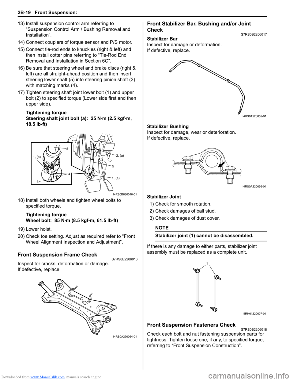
steering lower shaft (5) into steering pinion shaft (3)
with matching marks (4).
17) Tighten steering shaft joint lower bolt (1) and upper bolt (2) to specified torque (Lower side first and then
upper side).
Tightening torque
Steering shaft joint bolt (a): 25 N·m (2.5 kgf-m,
18.5 lb-ft)
18) Install both wheels and tighten wheel bolts to specified torque.
Tightening torque
Wheel bolt: 85 N·m (8.5 kgf-m, 61.5 lb-ft)
19) Lower hoist.
20) Check toe setting. Adjust as required refer to “Front Wheel Alignment Inspection and Adjustment”.
Front Suspension Frame CheckS7RS0B2206016
Inspect for cracks, deformation or damage.
If defective, replace.
Front Stabilizer Bar, Bushing and/or Joint
Check
S7RS0B2206017
Stabilizer Bar
Inspect for damage or deformation.
If defective, replace.
Stabilizer Bushing
Inspect for damage, wear or deterioration.
If defective, replace.
Stabilizer Joint
1) Check for smooth rotation.
2) Check damages of ball stud.
3) Check damages of dust cover.
NOTE
Stabilizer joint (1) cannot be disassembled.
If there is any damage to either parts, stabilizer joint
assembly must be replaced as a complete unit.
Front Suspension Fasteners CheckS7RS0B2206018
Check each bolt and nut fastening suspension parts for
tightness. Tighten loose one, if any, to specified torque,
referring to “Front Suspension Construction”.
5
4
1, (a)
3
2, (a)
1, (a)
5
I4RS0B630016-01
I4RS0A220054-01
I4RS0A220052-01
I4RS0A220056-01
1
I4RH01220007-01